AT&T
555-532-504
Issue 1, August 1988
AT&T SYSTEM 25
CALL MANAGEMENT SYSTEM
INSTALLATION AND
©1988 AT&T
All Rights Reserved
Printed in USA
Call Management System
Installation and
Startup Guide
Prepared by System 25
Warning
Contents
Introduction
1What’s in this Manual 2
Completed Planning and Implementation Forms 4
Assigning System 25 Port Numbers
5Agent Stations and Supervisor Station(s) 5
PC Jacks CU1 and CU2 5
Voice Announcement Unit(s) 5
CMS Lines 5
Transfer-Queue Lines 5
CMS Contingency Plan “Ghost” Voice Terminals 6
Installing CMS Hardware
7Setting Up the Voice Announcement Unit 7
Installing the CMS PC Interface Card in the PC 8
Disconnect the Power 8
Remove the Cover from the PC 8
Installing the Video Display Controller Card 10
Before You Insert the CMS PC Interface Card into the PC 10
Other Considerations 11
Insert the Interface Card into the PC 11
Reassemble the PC 15
Installing the Software
16Installing MS-DOS 16
Duplicating the CMS Diskettes 16
Copying the CMS Diskettes 16
Installing the CMS Software 19
Copying the CMS Software onto the PC’s Hard Disk 19
Setting the Time and Date 21
Starting CMS and Entering Data
Starting CMS
Guide to Entering and Editing Data
Moving the Cursor Responding to a Prompt Editing Data Within a Field Sending Data to CMS Validating Data
Using the Help Screens
Administering CMS
Administering Stations
Adding Agent Stations
Administering Supervisor Station(s)
Administering CMS PC Jacks (CU1 and CU2) When You Finish Administering Stations
Administering Lines and Line Groups
Assigning Line Group IDs Adding CMS Lines
Assigning Priority to CMS Lines
When You Finish Administering CMS Lines
Administering Transfer-Queue Lines
Adding Transfer-Queue Lines
When You Finish Administering Transfer-Queue Lines
Administering Announcements
Adding Voice Announcement Units
When You Finish Administering Announcements
Assigning Announcements to Line Groups
Selecting Announcement Units Assigning Announcements
When You Finish Assigning Announcements
Creating an Agent Directory
Adding Agents to the Agent Directory
When You Finish Creating the Agent Directory
Building a Shift Configuration
Selecting a Configuration Administering Agent Splits Naming a Split
Assigning Agents to Agent Splits When You Finish Administering Splits Administering Call Flow
When You Finish Administering Call Flow Saving Configuration Changes
Naming the Configuration When You Are Done
27 28 28 29 30 30 31 31 32 33 33 34 35 36 37 38 38 39 39 40 41 42 42 43 44 44 46 46 47 47 47 48 49 49 49
Printing System 25 Administration Instructions
50Printer Problems 51
Organizing the System 25/CMS Implementation Forms
Forms for PC Jacks, CU1 and CU2
Forms for CMS and Transfer-Queue Lines Forms for the Voice Announcement Unit(s) Forms for the Agent Stations
Forms for the Supervisor Voice Terminal Forms for the Transfer-into-Queue Single-Line
Voice Terminal DGC Contingency Plan When You Are Finished
53 53 54 54 55 56
56 56 56
Connecting CMS Equipment and Facilities to System 25
57Connecting the PC Jacks 58
Connecting Transfer-Queue Lines 59
Performing Software Translations for CMS
60When You Are Finished 61
Labeling Voice Terminals 62
When You Are Finished 62
Testing CMS
Tests for the CMS Contingency Plan
Log Agent Voice Terminals Out of Their DGC Groups Call Management Startup Test
Agent Status Tests Call Distribution Test Trunk Tests
Changing CMS Administration
63 63 65 66 67 68 69 70
Backing Up CMS and System 25 Administration
71Backing Up CMS Administration 71
Saving System 25 Translations 71
Storing CMS Planning and Implementation Forms 71
Introduction
The AT&T System 25 Call Management System Installation and Startup Guide (CMS Installation and Startup Guide) is intended for the System 25 CMS installer. This guide leads you through the following steps that get the Call Management System (CMS) up and running on the AT&T System 25 Communications System (System 25). They include:
● ● ● ● ● ● ● ● ● ● ● ● ● ● ●
Assigning System 25 port numbers to CMS equipment and facilities (trunks)
Setting up the voice announcement unit(s)
Unpacking and installing the AT&T Personal Computer (PC) Installing MS-DOS1
on the PC’s hard disk Preparing duplicate copies of the CMS diskettes Installing the CMS software on the PC’s hard disk Administering CMS on the PC
Printing System 25 administration instructions on the PC’s printer Organizing the System 25/CMS implementation forms
Connecting CMS hardware and facilities to System 25 Administering System 25 for CMS
Labeling the CMS agents’ and supervisor’s voice terminal feature buttons Testing CMS
Backing up CMS administration Saving System 25 translations
Once you have CMS up and running, the CMS Supervisor can then fine-tune the system, add shift configurations, and customize CMS to fit business needs. The CMS Supervisor should refer to the AT&T System 25 Call
Management System System Manual (CMS System Manual) for detailed
explanations and instructions.
The instructions in this CMS Installation and Startup Guide assume that: A System 25 PBX has been installed with sufficient hardware and building wiring to accommodate CMS equipment (i.e., voice terminals, PC jacks, and voice announcement units).
A dedicated PC is being used with CMS.
All components are on site and have the appropriate documentation.
1. MS-DOS is a registered trademark of Microsoft Corporation.
WHAT’S IN THIS MANUAL This manual guides you through the steps listed above, and is organized as follows:
Introduction
Explains the organization of this guide, and includes a list of the CMS Planning Forms and System 25/CMS implementation forms that must have been completed by the CMS Supervisor and the System 25 Administrator in order for you to install and administer CMS.
Assigning System 25 Port Numbers
Lists the CMS components for which port numbers must be assigned and the forms on which you record these port numbers.
Installing
Describes CMS PC.
Installing
Discusses
CMS Hardware
how to install and set up the voice announcement units and the
The Software
installing MS-DOS, and describes how to duplicate the CMS diskettes and use the duplicates to install the CMS software onto the hard disk. This section also explains how to set the time and date on the PC to ensure accuracy on the CMS reports.
Starting CMS and Entering Data
Gives a brief explanation about starting CMS and entering and editing data.
Administering CMS
Describes entering the information from the CMS Planning Forms into the system. Included are instructions for:
Administering stations
Administering lines and line groups Administering transfer-queue lines
Administering the voice announcement units and assigning them to line groups
Creating an agent directory
Building and naming at least one shift configuration
Printing System 25 Administration Instructions
Describes how to print the System 25 administration instructions used to administer System 25 to support CMS.
Organizing the System 25/CMS Implementation Forms
Describes how to organize the hand-completed and computer-generated System 25/CMS implementation forms for each CMS component.
Connecting CMS Equipment and Facilities to System 25
Lists the CMS hardware that needs to be connected to System 25.
Performing Software Translations for CMS
Describes the System 25 administration that must be done to support CMS. Also describes how to label the CMS agent and supervisor voice terminal feature buttons.
Testing CMS
Includes brief tests to verify that CMS has been set up correctly.
Backing Up CMS and System 25 Administration
Describes how to back up CMS administration onto the working copy diskette. A reminder to backup System 25 translations is included.
Guide to CMS Screens
Contains menu maps that illustrate the network of CMS screens and functions used during CMS administration and call management.
Completed Planning and Implementation Forms
The CMS Supervisor together with the System 25 Administrator must have completed the following forms prior to CMS installation. Directions for filling out the CMS planning and CMS/System 25 implementation forms can be found in the AT&T System 25 Call Management System Planning Guide.
System 25/CMS CMS Component CMS Planning Form I m p l e m e n t a t i o n F o r m
Agent stations Station Assignments One voice terminal Supervisor stations Planning Form implementation form foreach agent and supervisor
voice terminal.
PC jack CU1 Station Assignments One 34-Button Voice PC jack CU2 Planning Form Terminal implementationform for CU1, and one
implementation form for CU2.
Voice announcement Voice Announcement One Single-Line Voice
unit(s) Unit Planning Form Terminal implementation
form for each voice announcement unit.
CMS lines Line Groups Central Office Trunks
Planning Form form(s)
Central Office Trunk form(s) Transfer-queue Transfer-into-Queue (for the Loop Start trunks)
lines Planning Form
(optional feature) One Single-Line Voice
Terminal implementation form for each transfer-queue line.
Direct Group Calling List
CMS contingency None
plan One 34-Button Voice
Terminal implementation form for each DGC “ghost” voice terminal.
Group Coverage Plan
Assigning System 25 Port Numbers
System 25 port numbers must be assigned to each CMS component and recorded on the appropriate CMS planning and System 25/CMS
implementation forms discussed below. The System 25 Trunk Port Records form and the System 25 Voice and Data Records form in the AT&T System 25
Administration Records (Administration Records) binder must also be updated.
AGENT STATIONS AND Each agent or supervisor voice terminal must be assigned a port on an ATL SUPERVISOR STATION(S) Line Circuit Pack.
Enter the forms for Enter the
assigned port numbers on the voice terminal implementation these stations.
port numbers on the Station Assignments Planning Form.
PC JACKS CU1 AND CU2 PC jacks CU1 and CU2 must be assigned ports on the same ATL Line Circuit Pack.
Enter these port number assignments on the 34-Button Voice Terminal implementation forms designated for CU1 and CU2.
Enter the port numbers on the Station Assignments Planning Form.
VOICE ANNOUNCEMENT Assign each voice announcement unit a port on either a Tip Ring Line or
UNIT(S) Analog Line Circuit Pack.
CMS LINES
Enter the port number assignment on the Single-Line Voice Terminal implementation form for each voice announcement unit.
Enter the port number(s) on the Voice Announcement Unit Planning Form.
For each CMS line (Central Office trunk), assign a port on a Ground Start Trunk or a Loop Start Trunk Circuit Pack, as appropriate.
Enter the port number assignments on the Central Office Trunks implementation form(s) with “CMS Lines” next to “Trunk Use.” Enter the port numbers on the Line Groups Planning Form.
TRANSFER-QUEUE LINES Each transfer-queue line (used for the Transfer-into-Queue feature) requires a port on a Loop Start Trunk Circuit Pack and a port on a Tip Ring Line or Analog Line Circuit Pack.
Enter the port number(s) for the Loop Start trunk(s) on the Central Office Trunks implementation form(s) with “CMS Transfer-Queue Lines” next to “Trunk Use.”
Enter the port number for the single-line port on the single-line voice terminal implementation form designated for Transfer-Queue Lines and on the Transfer-into-Queue Planning Form.
CMS CONTINGENCY PLAN Each “ghost” 34-button voice terminal for the CMS contingency plan requires “GHOST” VOICE a valid System 25 port number assignment. Since no hardware will be TERMINALS connected to these ports, assign port numbers on a non-existent circuit pack.
For example, if you-are working with a two-cabinet system, and you need to assign ports for two “ghost” voice terminals, use port numbers on an imaginary ATL Line Circuit Pack in an imaginary third cabinet, for example, port numbers 31201 and 31202.
NOTE: If you have a fully loaded 3-cabinet system, you will have to reserve a real port on a real ATL Line Circuit Pack for each “ghost” voice terminal.
Enter the port assignment on the 34-Button Voice Terminal
implementation form for each CMS contingency plan “ghost” voice terminal.
Be sure to add CMS contingency plan “ghost” voice terminal(s) on the System 25 Voice and Data Station Records form in the Administration Records binder. Write “CMS Ghost” in the Employee Name column.
IMPORTANT: The administration of fictitious System 25 voice terminal ports causes the following message to be entered as a Permanent System Alarm and also causes the Alarm light on the Attendant console to flash following a Warm Start of System 25:
XXXXX Port Board Missing But Administered
(XXXXX represents the port number of the fictitious port.) The Attendant Alarm light can be turned off by removing the
Permanent System Alarm message through System 25 administration. The System 25 translations for the fictitious port(s) must not be removed or the CMS contingency plan, mentioned above, will not work.
Installing CMS Hardware
Use the following instructions and suggestions for installing and setting up the CMS PC and voice announcement unit(s).
Setting Up the Voice Announcement Unit
A CMS can have up to four voice announcement units. Use the instructions that come with the DACON voice announcement unit to unpack and set up the unit(s) that will be used with CMS.
When the voice announcement units have been set up, have the person responsible record a Day Service announcement on each unit. A Night Service announcement can also be recorded. For directions on recording a message, refer to the instructions that came with the unit or see “Recording Messages” in Section 2, “Understanding CMS,” in the CMS System Manual.
NOTE: Leave three or four seconds of silence at the beginning of the message to ensure that a caller will hear the delay message from the beginning.
After the messages are recorded, time the length of the Day Service message recorded on each announcement unit. (Be sure to include the three or four seconds of silence at the beginning of the message.) Enter the number of seconds in the “Maximum msg length” column on the Voice Announcement Unit Planning Form.
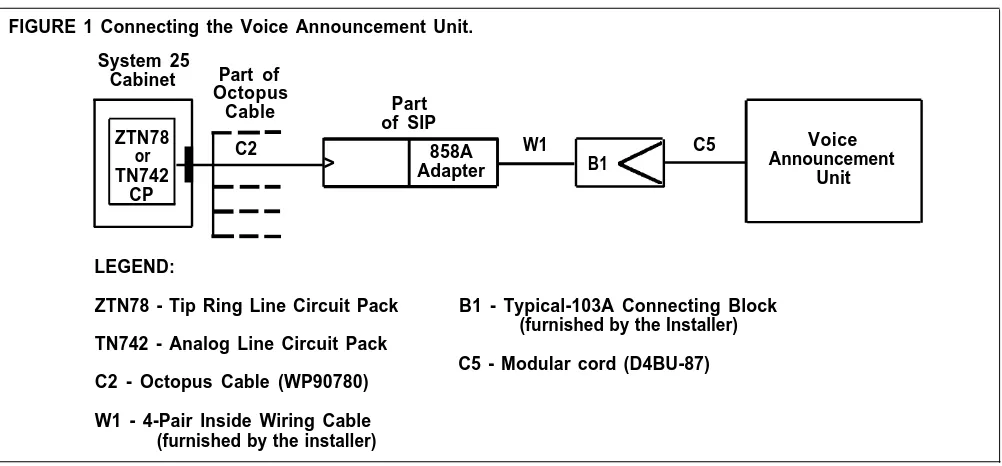
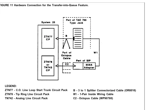
If AT&T tape answering machine units will be used for Night Service, unpack and set up these units also. Follow the instructions that came with the unit. Figure 1 shows a connectivity diagram for a voice announcement unit.
FIGURE 1 Connecting the Voice Announcement Unit. System 25
Cabinet Part of Octopus
Part Cable
ZTN78 of SIP
or C2 > 858A W1 B1 C5 AnnouncementVoice
TN742 Adapter Unit
CP
LEGEND:
ZTN78 - Tip Ring Line Circuit Pack B1 - Typical-103A Connecting Block (furnished by the Installer) TN742 - Analog Line Circuit Pack
C5 - Modular cord (D4BU-87) C2 - Octopus Cable (WP90780)
W1 - 4-Pair Inside Wiring Cable (furnished by the installer)
Installing the CMS PC Interface Card in the PC
DISCONNECT THE POWER
Unpack and install the PC’s main unit, keyboard, monitor, and printer using the instructions in the guides that came with the equipment. Then use the following procedure for installing the AT&T CMS PC Interface Card in your PC. A flat-blade screwdriver is the only tool you need.
1 Turn off the power to the PC.
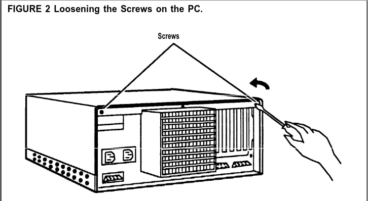
REMOVE THE COVER FROM THE PC
2 Turn off the power to the printer and any other peripheral equipment. 3 Unplug the computer’s power cord from the electrical outlet.
DANGER
Failure to disconnect the power may damage the computer or result in electrical shock.
1 Locate the two screws on the upper back of the unit, as shown in Figure 2. Using a flat-blade screwdriver, unscrew them about 1/4 of an inch, or until they move freely.
NOTE: Do not try to unscrew the middle screw. It holds the unit together.
FIGURE 2 Loosening the Screws on the PC.
Screws
2 Stand in front of the unit and place your hands on the sides of the cover, as shown in Figure 3.
FIGURE 3 Sliding the Cover of the PC Forward.
Base
1/8"
3 Brace the base of the unit against your hip or thigh, and firmly slide the cover toward the front of the unit. (It will move only about 1/8 of an inch.)
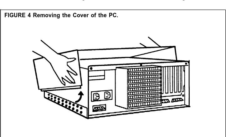
NOTE: The cover fits snugly, and it may be difficult to move out of its normal position. If the cover does not move, you may have to loosen the screws a bit more or gently pry the cover forward with the screwdriver. 4 Place your hands on the sides of the cover toward the rear and tilt it so
that the rear section is higher than the front, as shown in Figure 4.
FIGURE 4 Removing the Cover of the PC.
5 Lift and remove the cover from the base unit and set it aside.
INSTALLING THE VIDEO DISPLAY CONTROLLER CARD
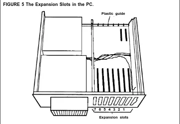
Once you have removed the cover from your PC, you are ready to insert the Video Display Controller Card and the CMS PC Interface Card.
In your PC there are seven expansion slots numbered 1 through 7, as shown in Figure 5. At the front of the PC, there’s a plastic guide aligned with each expansion slot. The Video Display Controller Card and the CMS PC Interface Card must each fit into an expansion slot receptacle and its corresponding plastic guide.
Plastic guide
BEFORE YOU INSERT THE CMS PC INTERFACE CARD INTO THE PC
FIGURE 5 The Expansion Slots in the PC.
7 6 5 4 3 2 1
Expansion slots
Insert the Video Display Controller Card into one of the PC expansion slots according to the directions that came with your PC.
Before you begin to insert the CMS PC Interface Card in the PC, you should note these important points:
A Note on the RAM Address and the IRQ Select
Each card in a personal computer requires exclusive use of certain areas (addresses) in the computer’s memory. Two PC cards cannot share the same address(es).
The CMS PC Interface Card uses the following RAM (Random Access Memory) hexadecimal addresses and IRQ (Interrupt Request) select.
These are set by the factory and cannot be changed.
RAM C0000—C03FF IRQ 3
If another card installed in the PC uses the RAM address C0000—C03FF and/or IRQ 3, the RAM address and the IRQ select on that card must be changed so that they are not the same as those on the CMS PC Interface Card. Otherwise, CMS will not function properly. If they cannot be changed, you must remove the other card.
NOTE: A card connected to the hard disk already occupies an expansion slot in the PC. Neither the address of this card nor the address of the Video Controller Card needs to be changed.
OTHER CONSIDERATIONS Also note the following important considerations when you are ready to insert the card in the PC:
Avoid touching the gold “fingers” at the base of the card. Always hold the card by its top corner edges.
As you insert the card, be sure that you do not bend it.
INSERT THE INTERFACE To insert the CMS PC Interface Card in one of the expansion slots, follow CARD INTO THE PC these directions:
1
2
3
4
Select an empty slot for the CMS PC Interface Card.
If there are other cards inside the unit, be sure they do not interfere with the space you need for the CMS PC Interface Card.
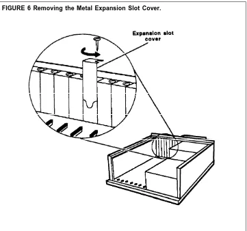
Using the flat-blade screwdriver, remove the screw from the metal cover of the expansion slot that you have chosen. (See Figure 6.) Set the screw aside because you will need it later.
Remove the metal expansion slot cover by sliding it up, as shown in Figure 6.
If required, use the screwdriver to pry off the plastic slot cover that protects the expansion slot. (Position the screwdriver behind, rather than inside, the unit to do this.)
FIGURE 6 Removing the Metal Expansion Slot Cover.
NOTE: In Figure 6, neither the hard disk controller card in slot 7 of the PC nor the Video Display Controller Card is shown.
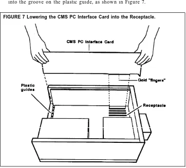
5 Make sure the expansion slot is clear. Position the colored wires crossing the slot so they lie beneath the card as you install it.
6 Holding the CMS PC Interface Card by its top corner edges, lower the card into the expansion slot receptacle you have chosen, as shown in Figure 7. (Do not try to insert the card through the back of the unit.) 7 Position the card so the electrical contacts, the gold “fingers,” are aligned
with the receptacle in the expansion slot and the back edge of the card fits into the groove on the plastic guide, as shown in Figure 7.
FIGURE 7 Lowering the CMS PC Interface Card into the Receptacle.
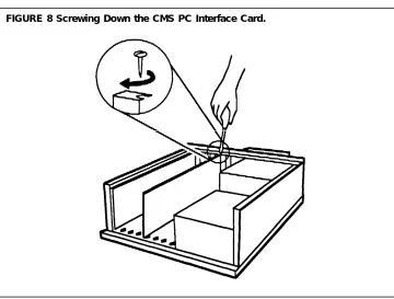
8 Press down on the top edge of the card until you feel and hear the card “lock” into place. The card is “locked” when the frame of the card is flush with the frame of the unit.
If the card tilts or wobbles when you press on either end, the card is not properly installed. Take out the card and reinsert it. Be careful that you do not bend the card.
Make sure that the CMS PC Interface Card is not touching any other card. If it is, move the CMS PC Interface Card to another slot. Be sure the bracket that replaces the slot cover slides into the appropriate slot.
9
Screw down the CMS PC Interface Card with the screw you removed
from the metal expansion slot cover, as shown in Figure 8.
FIGURE 8 Screwing Down the CMS PC Interface Card.
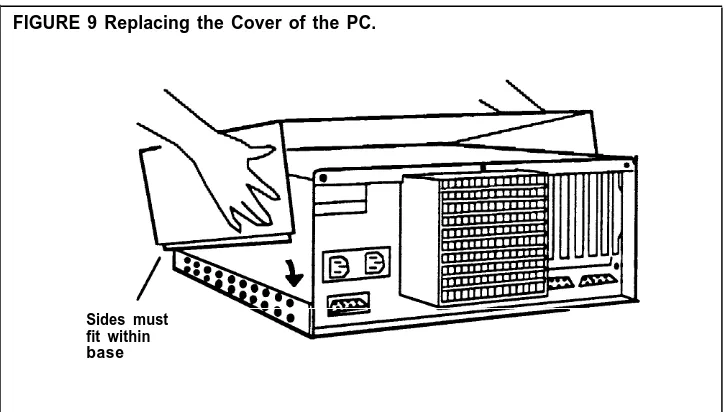
REASSEMBLE THE PC When you have inserted both the Video Display Controller Card and the CMS PC Interface Card, reassemble the PC by following this procedure: 1 Face the front of the unit and lower the front of the cover so that the rear
is slightly higher than the front.
2 Align the front of the cover with the front of the base, as shown in Figure 9. Make sure that the sides of the cover fit within the base of the unit at the front, and that the plastic tabs at the front of the cover are under the disk drive.
FIGURE 9 Replacing the Cover of the PC.
Sides must fit within base
3
4
5
6
7
8
Lower the back of the cover onto the base.
Slide the cover about 1/8 of an inch toward the front of the unit.
Then, slide the cover toward the rear of the unit. The sides of the cover should now fit within the base.
Tighten the two screws that you previously loosened at the back of the unit.
If you haven’t done so already, connect the monitor, keyboard, and printer according to the directions that came with the PC.
Plug the PC’s power cord into an ac outlet.
Installing the Software
Installing MS-DOS
Turn on the PC and then install MS-DOS onto the PC’s hard disk following the instructions in the user guide that came with the MS-DOS diskette.
Duplicating the CMS Diskettes
COPYING THE CMS DISKETTES
To protect the original CMS floppy diskettes from damage or wear, use blank diskettes to make working copies of the originals. Then store the originals in a safe place in case they are needed later.
You need the following to make the duplicates: The PC with MS-DOS installed on its hard disk
The CMS diskettes, labeled “SYSTEM 25 CMS SYSTEM” and “SYSTEM 25 CMS REPORT AND ADMIN” (packaged with the CMS binder) Two blank diskettes (also packaged with the CMS binder).
To make duplicate copies of the original CMS diskettes: 1 Turn on the PC (if it isn’t already on).
2 When the c> prompt appears, type:
diskcopy a: a:
and press [ Enter ] . This message appears:
Insert source diskette in drive A:
Strike any key when ready.
NOTE: PC responses may be slightly different from the ones shown here, depending on the version of MS-DOS you are using.
3 Insert the CMS diskette, with the label “SYSTEM 25 CMS SYSTEM” facing upwards, into drive A. (The notch in the side of the diskette should be on the left). When you hear a click, indicating that the diskette has been fully inserted, press down the latch on drive A until you hear the latch lock. The “SYSTEM 25 CMS SYSTEM” diskette is the “source” diskette, the diskette that contains the information being copied.
4 When you are ready, press any key.
The in-use light on disk drive A comes on while the system is reading the source diskette.
CAUTION
Do not remove a diskette from the drive while the in-use light is on.
5
6
7
8
9
10
When the system has read the the diskette, the following messages are displayed:
Insert target diskette in drive A: Strike any key when ready.
When the in-use light on drive A goes off, remove the source diskette, insert a blank diskette, and press any key. This diskette is the “target” diskette, the diskette onto which the information is being copied. The in-use light comes on while the system copies the information onto the target diskette. If the blank diskette is not formatted, the message
Formatting While Copying
appears on the screen.
NOTE: Depending on the amount of memory the PC has, the system may prompt you to swap diskettes during diskcopy.
When the copying process is finished, you see: Copy another (Y/N)?
Remove the duplicate diskette, and, using a felt tip pen, write “SYSTEM 25 CMS SYSTEM WORKING COPY”on a label, apply the label to the diskette, and put the diskette in its paper sleeve. Return the original diskette to its paper sleeve.
Type y. Do not press [ Enter ] . The following messages appear: Insert source diskette in drive A:
Strike any key when ready.
Insert the CMS diskette labeled “SYSTEM 25 CMS REPORT AND ADMIN” into drive A. This is the “source” diskette.
Repeat Steps 4 and 5, using the second blank diskette as the “target” diskette.
Type n when prompted to copy another diskette.
11 When the c> prompt appears, remove the duplicate diskette, write “SYSTEM 25 CMS REPORT AND ADMIN WORKING COPY” on a label, apply the label to the diskette, and store the diskette in its paper sleeve. Return the original diskette to its paper sleeve.
12 Store both original CMS diskettes in a safe place.
You are now ready to install the CMS software using the working copies of the CMS diskettes.
Installing the CMS Software
Installing the CMS software involves copying the contents of the two CMS working copy diskettes onto the PC’s hard disk.
Perform the following software installation procedures to install the CMS software. When you are finished, the system will have copied the files required for CMS operations onto the PC hard disk.
COPYING THE CMS To copy the CMS software onto the PC’s hard disk: SOFTWARE ONTO THE
PC’S HARD DISK 1 Insert the diskette labeled “SYSTEM 25 CMS SYSTEM WORKING COPY” into drive A.
2 At the c> prompt, type
a:\cmsinstall
and then press [ Enter ] .
The following messages appear in the upper portion of the screen: ****SYSTEM 25 Call Management System
****Installation Procedure
These messages remain on the screen throughout the installation procedure. Additional messages appear in the lower area of the screen. 3 While the installation procedure is in progress, the following message
usually appears on your screen:
****Installation Now In Progress. Please Wait...
However, the installation procedure could be interrupted if either of the following situations exist:
— If there are errors on the CMS working copy diskette that prevent the installation program from continuing, the following messages appear on the screen:
****ERROR on Installation Floppy Disk Try Installation from Another Floppy
NOTE: Discard the CMS working copy diskette, make another copy of the original CMS diskette, and then begin the CMS software
installation procedure again.
— If there is insufficient storage space on the hard disk for new information, the following messages appear on the screen:
****Insufficient Disk Space for CMS. An Additional xxxK is Required.
Delete Old Files and Try Installation Again.
NOTE: If you need directions on using the MS-DOS “delete” (del) and “directory” (dir) commands to delete files, see the user’s guide that came with the MS-DOS diskette.
4 After the contents of the “SYSTEM 25 CMS SYSTEM WORKING COPY” diskette have been copied onto the hard disk, the following messages are displayed:
****Please remove the diskette currently in floppy disk drive A. ****Insert the diskette labeled SYSTEM 25 CMS REPORT AND ADMIN
into drive A.
Press ‘c’ to continue or ‘q’ to quit.
5 Remove the “SYSTEM 25 CMS SYSTEM WORKING COPY” diskette and place it in its protective cover.
6 Insert the diskette labeled “SYSTEM 25 CMS REPORT AND ADMIN WORKING COPY” into the drive A and press c.
7 Once the installation program has copied all the CMS programs and files onto the hard disk, the final installation messages appear on the screen:
****Call Management System Successfully Installed. ****Please remove the diskette currently in floppy disk drive A. ****Reboot the system by holding down ‘CTRL’ and ‘ALT’ while
pressing ‘DEL.’
8 Remove the “SYSTEM 25 CMS REPORT AND ADMIN WORKING COPY” diskette from the disk drive and place it in its paper sleeve. 9 Reboot the system by holding down [ Ctrl ] and [ Alt ] while pressing [ Delete ] .
After Resident Diagnostics are run, the CMS Menu appears on the screen. 10 Store the working CMS diskettes in a safe place.
Setting the Time and Date
Since the date and time are important parts of the CMS statistics, it is important that the PC screen and reports show the correct date and time. Examine the date and time displayed in the top right corner of the CMS Menu screen. If either needs to be changed, exit CMS and return to MS-DOS by pressing [ F8 ] (labeled “Exit to DOS“).
To change the date on the PC:
1 At the c> prompt, type date and press [ Enter ] . The following messages appear on the screen:
Current date is Wed 04-07-1988 Enter new date (mm-dd-yy):
2 Type in the correct date in the form mm-dd-yy (for example, 04-08-88 ) and press [ Enter ] .
To change the time on the PC:
1 At the c> prompt, type time and press [ Enter ] . The following messages appear on the screen:
Current time is 12:15:30.80 Enter new time:
2 Type in the correct hour and minute in the form hh:mm (for example,
9:03) and press [ Enter ] . (MS-DOS works on the basis of a 24-hour clock,
so to enter the time as 2:30 P.M., type 14:30.)
Starting CMS and Entering Data
STARTING CMS
This section describes how to access the CMS Menu, the starting point for CMS activities. It also explains how to respond to prompts and enter and edit data.
To start CMS and access the CMS Menu:
● Turn on the PC.
After resident diagnostics are run, the CMS Menu, shown below, appears.
CMS MENU CMS CMS1.0 9:19a 04/18
CALL M A N A G E M E N T S Y S T E M ( C M S )
FOR THE A T & T S Y S T E M 2 5 PBX
© 1988 by AT&T
F1 Start Call Management F4 Administer CMS F5 Print Reports F8 Exit to DOS
F10 - Help F Start F Admin F Print F Exit 1Call Mgt 4 CMS 5Reports 8 to DOS
NOTE: If the PC is already on, and the c> prompt appears on the screen, do the following to display the CMS Menu:
1 Type cd \cms then press [ Enter ] . 2 Type cms then press [ Enter ] .
Once the CMS Menu appears, you are ready to enter data.
Guide to Entering and Editing Data
Entering and editing data is easy. You enter data by pressing a function key and responding to the prompt(s) that appears on the PC screen. A prompt is a message that appears on the PC screen requesting that you enter
information. This information is entered in fields, the spaces provided in the prompt for your response. Whenever a prompt appears, the function keys are relabeled with data entry functions, as shown below.
Prompt line Function keys
CONFIGURE DELAY ADMIN CMS1.0 3:31p 04/18
AGENT SPLITS ANSWER/FORCE DELAY |--Agent--| |--Agent--| Num Answer Force Split PDC ID Split PDC ID Group Lines Delay Delay 1 PUBLIC 401 LINDA 4 SUPPT 417 CRAIG A PUBLC 9 10s Off
402 JOEL 418 BARB B BUSNS 6 0s On 403 IEN 424 CJ C CHART 5 5s Off 404 JENNY 5 - D - 0 5s Off 405 SCOTT 6
-406 BILL
2 BUSNS 407 SARAH CALL FLOW
408 JOHN Flow
409 JIM |-Splits-| Intra Spl Thresh 3 CHART 410 BERNE Gp Main Sec Flow 1 50s
411 DON A 1 4 On 2 30s 412 ALLAN B 2 3 Off 3 30s 4 SUPPT 415 ANDY C 3 2 Off 4 30s 416 LOU D - - Off 5 30s 6 30s Configuration #1 - DAY
ANS/FORCE DELAY: Grp(A-D):_ Ans Delay (0-99 sec):_ Force Delay (ON/OFF):_ F Cancel FPrevious F Next F Enter 1 Prompt 5 Field 6 Field 8 Data
MOVING THE CURSOR Many CMS prompts contain several fields, as in the following example:
ADD AGENT: Last Name: First: ID:
When a prompt appears, the cursor is positioned at the beginning of the first field. Use the keys shown below to move the cursor within a prompt.
To move the cursor
to the beginning of the previous field.
RESPONDING TO A PROMPT
Press Or
[ F5 ] (Previous Field) [ Shift ] + [ Tab ] (both at once)
[ F6 ] (Next Field) [ Tab ]
[ → → ] (the right arrow key on the numeric keypad)
[ Backspace ] [ ← ← ] (the left arrow key on the numeric
keypad)
to the beginning of the next field.
one character to the right. This does not work in a blank field.
one character to the left. This does not work in a blank field.
Follow these guidelines when completing the fields in a prompt:
Depending on the field, you may enter letters, numbers, special characters (such as * or %), or a combination of the three.
You can type letters using uppercase or lowercase. names, all letters you type appear in uppercase on type lowercase letters. Letters in agent names, on appear exactly as you type them.
Except for agent the screen, even if you the other hand, always
Spaces are not allowed between characters in a field, so you may want to use underlines instead.
NOTE: To cancel any prompt, press [ F1 ] (labeled “Cancel Prompt”) or [ Delete ] . Any data you entered in the prompt fields are ignored, the prompt disappears, and the function key labels change from data entry labels to the labels for the particular CMS screen.
EDITING DATA WITHIN A Follow the instructions shown in the table below to change entries within a
FIELD field.
To Do this
Change a character in a field. Move the cursor to the incorrect character and type another character over it.
Add characters at the end of an Press [ → → ] after the last character
entry. and type the additional characters.
Insert characters in an entry. Move the cursor to the first character you want to change and retype the entire entry from that character onward. (You cannot use
[ Insert ] to insert a character between other characters.)
Replace a long entry with a shorter Type over the characters you want
one. to change, then press the space bar
after the last character of the new entry. The remaining characters in the previous entry disappear. For example, to change “Joseph” to “Joe”:
1 Move the cursor to “s” 2 Type “e”
3 Press the space bar.
The letters “eph” disappear.
SENDING DATA TO CMS When you finish filling in the necessary information in a field, press [ F8 ] (labeled “Enter Data”) or [ Enter ] to send the data to CMS. The cursor can be in any field when you press these keys.
VALIDATING DATA CMS validates the information entered in two ways:
1 The first type of validation occurs as you type each piece of information in a field. If you make an invalid entry (for instance, entering a letter in a numeric field), the PC beeps, the character does not display, and the cursor remains in the same position so you can make another entry. 2 The second type of validation occurs after you press [ F8 ] (labeled “Enter
Data”). At this point, CMS begins to validate each field of information from left to right. If there is an invalid entry or you left a required field blank, the PC beeps, and an error message appears above the prompt. The cursor returns to the first error field so you can correct the entry.
USING THE HELP To receive more information about the function keys for individual screens, SCREENS press [ F10 ] (labeled “Help”) when you are looking at the screen. A Help
screen describing the purpose of each function key appears.
To exit a Help screen and return to your previous place, press the space bar. If you press a function key to exit a Help screen, CMS exits the Help screen and then performs the labeled function of that particular function key.
Administering CMS
Administering CMS involves entering information from the following CMS Planning forms:
● Station Assignments Planning Form ● Line Groups Planning Form
● Transfer-into-Queue Planning Form ● Voice Announcement Unit Planning Form ● Agent Directory Planning Form
● Shift Configuration Planning Form
NOTE: It is important to enter the information exactly as it appears on the forms. After all the information from a form has been entered, it is strongly recommended that the displayed information be checked for completeness and accuracy. This will help prevent problems later in the installation and startup process.
The starting point for administration of CMS is the Administration Menu, shown below. Press [ F4 ] (labeled “Admin CMS”) on the CMS Menu to reach this screen.
ADMINISTRATION MENU ADMIN CMS1.0 9:35a 04/18
Administration Menu F1 Administer Stations
F2 Administer Lines, Line Groups and Announcements F3 Agent Directory
F4 Shift Configurations F5 Set Options
F6 Select Exception Thresholds to be Monitored F7 Print SYSTEM 25 Administration Instructions F8 Exit Administration (Go to CMS MENU)
SELECT ADMINISTRATION FUNCTION
F10 - Help F Admin F Agent F Lines/ F Config F Set F Select FS25 Admn F Exit 1Stations 2Line Gps 3Directry 4 List 5 Options 6Exceptns 7Instrctn8 Admin
Administering Stations
Administering CMS stations for the first time involves:
Entering the System 25 PDC, port number, and voice terminal type for each agent station (voice terminal)
Entering the System 25 PDCs and port numbers for one or two CMS Supervisor stations Type 304 304 304 USE SUPVR STA: PDC
430 Port #11001
ADDING AGENT STATIONS
Entering the System 25 PDCs and port numbers for PC jacks CU1 and CU2.
Before you begin to administer stations, make sure you have the completed Station Assignments Planning Form in front of you.
Press [ F1 ] (labeled “Admin Stations”) on the Administration Menu to select the Administer Stations screen. The Administer Stations screen shown below contains sample data.
ADMINISTER STATIONS ADMIN CMS1.0 9:44a 04/19
PDC Port # 401 11101 402 11102 403 11103 404 11104 405 11105 406 11106 407 11107 408 11108 409 11201 410 11202 AGENT STATIONS Type 304 304 304 304 304 304 304 304 304 304 PDC 411 412 413 414 415 416 417 418 424 Port # 11203 11204 11205 11206 11207 11208 11004 11006 10902 304 304 308 304 304
307 Other Connections
431 11002 PC Jack CU1: 600 11003 PC Jack CU2: 601 11005
F10 - Help F Add F Remove F Change F Admin F Admin F Admin 1Agnt Stn 2Agnt Stn 3Agnt Stn 5Supervsr 6PC Jacks 8 Menu
You add an agent station to CMS by identifying its System 25 PDC, port number and voice terminal type. This information is on the completed Station Assignments Planning Form.
To 1
2
add an agent station:
Press [ F1 ] (labeled “Add Agnt Stn”). The following prompt appears:
ADD AGENT STATION: PDC: Port #: T y p e : _
Refer to the Agents Station Assignments section of the Station
Assignments Planning Form, and enter the agent station information in the appropriate fields. Then press [ F8 ] (labeled “Enter Data”).
The prompt disappears, the function key labels change, and the agent station appears on the screen.
NOTE: If you make a typing error, before pressing [ F8 ] , or if, after pressing [ F8 ] , the validation check finds an error, you can use either the function keys [ F5 ] (labeled “Previous Field”) and [ F6 ] (labeled “Next Field”), or the right and left arrow keys to position the cursor and make the necessary corrections.
To change agent station information after it has been accepted by CMS and appears in the list of agent stations, you can do the following:
— To change the PDC you must first remove the agent station by pressing [ F2 ] (labeled “Remove Agnt Stn”). Then, add the agent station correctly using [ F1 ] (labeled “Add Agnt Stn”).
— To change only the Port # or Type field, press [ F3 ] {labeled “Change Agnt Stn”). Type in the PDC field and the field(s) (Port # and/or Type) that you want to change, Then press [ F8 ] (labeled “Enter Data”).
3 Repeat Steps 1 and 2 for each agent station.
ADMINISTERING In the Supervisor Station Assignments section of the Station Assignments SUPERVISOR STATION(S) Planning Form, one or two supervisor stations are identified.
To add the supervisor station(s):
1 Press [ F5 ] (labeled “Admin Supervsr”) from the Administer Stations screen.
The following prompt appears:
SUPERVISOR STATION(S): PDC: Port # : 2nd PDC: 2nd Port #:
2 Referring to the Station Assignments Planning Form, enter the supervisor station(s) information in the appropriate fields.
NOTE:
If you are adding only one supervisor station, fill out the first two fields (PDC and Port #), and leave the third and fourth fields (2nd PDC and 2nd Port #) blank.3 Press [ F8 ] (labeled “Enter Data“).
The prompt disappears, the function key labels change, and the supervisor station(s) appears on the screen.
NOTE: If you make a typing error before pressing [ F8 ] , or if, after pressing [ F8 ] , the validation check finds an error, you can use either the function keys [ F5 ] (labeled “Previous Field”) and [ F6 ] (labeled “Next Field”), or the right and left arrow keys to position the cursor and make the necessary corrections.
To change supervisor station information after it has been accepted by CMS and appears in the Other Connections section of the screen, press [ F5 ] (labeled “Admin Supervsr”). Type in the PDC field and/or Port # that you want to change. Then press [ F8 ] (labeled “Enter Data”).
ADMINISTERING CMS PC The CMS PC Interface Card in the PC has two jacks (labeled CU1 and CU2) JACKS (CU1 AND CU2) for connecting to System 25. Administer the two CMS PC jacks by
identifying their System 25 PDCs and port numbers, as recorded on the PC Jack Assignments section of the Station Assignments Planning Form. To administer CMS PC jacks:
1 Press [ F6 ] (labeled “Admin PC Jacks”) from the Administer Stations screen.
The following prompt appears:
PC JACKS: CU1-PDC: CU1-Port #: CU2-PDC: CU2-Port #:
2 Enter the information for CMS PC jacks CU1 and CU2 in the appropriate fields, and press [ F8 ] (labeled “Enter Data”).
The prompt disappears, the function key labels change, and the CMS PC jack information appears on the screen.
NOTE: If you make a typing error before pressing [ F8 ] , or if, after pressing [ F8 ] , the validation check finds an error, you can use either the function keys [ F5 ] (labeled “Previous Field”) and [ F6 ] (labeled “Next Field”), or the right and left arrow keys to position the cursor and make the necessary corrections.
To change PC jack information after it has been accepted by CMS and appears in the Other Connections section of the screen, press [ F6 ] (labeled
“Admin PC Jacks”). Type in the PDC(s) and/or port number(s) that you want to change for the CU1 and/or CU2 PC jacks. Then press [ F8 ] (labeled “Enter Data”).
WHEN YOU FINISH ADMINISTERING STATIONS
Carefully check the information displayed on the Administer Stations screen against the information on the Station Assignments Planning Form. Make corrections if necessary.
Then press [ F8 ] (labeled “Admin Menu”) to return to the Administration Menu.
Administering Lines and Line Groups
Press [ F2 ] (labeled “Lines/Lines Gps”) on the Administration Menu to display the Administer Line Groups screen, shown below with sample data.
ADMINISTER LINE GROUPS ADMIN CMS1.0 2:52p 04/18
|---Line----Group SbGrp Port # ID A PUBLIC PL 10401 L3070
PL 10402 L3071 PL 10403 L3072 PL 10404 L3073 PW 10405 W4185 PW 10406 W4186 PS 10407 S4950 PS 10408 S4951 Q1 10701 Q500
LINE GROUPS
---| |---Line---| Tk # Typ P Group SbGrp Port # ID Tk # Typ P 3070 G C CHART CL 10603 L1234 1234 G 3071 G CL 10604 L1235 1235 G 3072 G CW 10605 W3000 3000 G 3073 G CW 10606 W3001 3001 G 4185 G CW 10607 W3002 3002 G 4186 G
4950 G + D 4951 G + 8000 L + B BUSNS BW 10501 W1242 1242 G
BW 10502 W1243 1243 G BW 10503 W1244 1244 G BW 10504 W1245 1245 G BL 10601 L8300 8300 G BL 10602 L8301 8301 G
F10 - Help F Add CMS F Remove FMove CMS FChg CMS FAsgn/Chg F Admin F Admin F Admin 1 Line 2CMS Line 3 Line 4LineInfo 5Group ID 6Xfr Que 7 Anncs 8 Menu
Make sure you have a completed Line Groups Planning Form in front of you. Refer to it as you assign line group IDs, add lines, and assign priority lines. Select an administration task by pressing the appropriate function key for the activity you want to perform. Then enter data in response to the prompt(s). Since line groups are being administered for the first time, follow this order: 1
2
3
ASSIGNING LINE GROUP To IDS
1
Assign line group IDs with [ F5 ] (labeled “Asgn/Chg Group ID”). Add CMS lines with [ F1 ] (labeled “Add CMS Line”).
Where indicated on the Line Groups Planning Form, designate certain lines as priority lines with [ F4 ] (labeled “Chg CMS LineInfo”).
assign a line group ID:
Press [ F5 ] (labeled “Asgn/Chg Group ID”) on screen.
The following prompt appears:
ASSIGN/CHANGE GROUP ID: Group (A-D):
the Administer Line Groups
New ID:
ADDING CMS LINES
2 Enter the line group letter and the line group ID. Then press [ F8 ] (labeled “Enter Data”).
NOTE: If you make a typing error before pressing [ F8 ] , or if, after pressing [ F8 ] , the validation check finds an error, you can use either the function keys [ F5 ] (labeled “Previous Field”) and [ F6 ] (labeled “Next Field”), or the right and left arrow keys to position the cursor and make the necessary corrections.
To change the line group ID after it has been accepted by CMS and appears on the screen, press [ F5 ] (labeled “Asgn/Chg Group ID”). Enter the line group letter and the new line group ID. Then press [ F8 ] (labeled
“Enter Data”).
3 Repeat Steps 1 and 2 for each line group.
To add a CMS line and assign it to a line group: 1 Press [ F1 ] (labeled “Add CMS Line”).
The following prompt appears:
ADD LINE: Grp (A-D):__ SubGrp:___ Port #: ID: Trunk #: Type:_
2 Enter the necessary line information in each field. (If a line has not been assigned a sub-group ID, press [ F5 ] (labeled “Next Field”) to skip that field.)
3 Press [ F8 ] (labeled “Enter Data”).
The prompt disappears, the function keys are relabeled, and the new line appears on the screen.
NOTE: If you make a typing error before pressing [ F8 ] , or if, after pressing [ F8 ] , the validation check finds an error, you can use either the function keys [ F5 ] (labeled “Previous Field”) and [ F6 ] (labeled “Next Field”), or the right and left arrow keys to position the cursor and make the necessary corrections.
To change line information after it has been accepted on the screen:
a Press [ F4 ] (labeled “Chg CMS LineInfo“).
by CMS and appears
b Enter the ID of the CMS line you want to change; then press [ F8 ] (labeled “Enter Data”).
c When the secondary prompt displays, enter line information in the field(s) you want to change; then press [ F8 ] (labeled “Enter Data”).
4
Repeat Steps 1 through 3 for each line.ASSIGNING PRIORITY TO For each line that was assigned priority (indicated by a “+” in the “Priority CMS LINES (+)” column on the Line Groups Planning Form), do the following:
1 Press [ F4 ] (labeled “Chg CMS LineInfo”) on the Administer Lines Groups screen.
The following prompt appears:
CHANGE CMS LINE INFORMATION: for Old Line ID:
2 Enter the line ID of the line to be assigned priority. 3 Press [ F8 ] (labeled “Enter Data”).
A second prompt appears:
Line XXXXX: SbGrp:___ Prt#: ID: Trk #: Typ:_Pri(ON/OFF):
4 Press [ F6 ] (labeled “Next Field”) until the cursor is in the Pri(ON/OFF) field.
5 Type on to turn priority on for the line. 6 Press [ F8 ] (labeled “Enter Data”).
The prompt disappears, the function keys are relabeled, and a “+” appears on the screen in the Priority (P) column for that line.
7 Repeat Steps 1 through 6 for each CMS line that was assigned priority on the Line Groups Planning Form.
WHEN YOU FINISH ADMINISTERING CMS LINES
Carefully review the Administer Line Groups screen to make sure all the information from the Line Groups Planning Form is entered correctly. Make corrections if necessary.
If the Transfer-into-Queue Planning Form is completed, press [ F6 ] (labeled “Admin Xfr Que”). Otherwise, press [ F7 ] (labeled “Admin Anncs”) and continue with “Administering Announcements” later in this guide.
Administering Transfer-Queue Lines
If the Transfer-into-Queue Planning Form is completed, you need to
administer transfer-queue lines. Of the 28 lines available per line group, three can be designated as transfer-queue lines. Each transfer-queue line is
assigned ports on two System 25 circuit packs — a trunk port (on a Loop Start Trunk Circuit Pack) and a single-line port (on a Tip Ring Line or Analog Line Circuit Pack).
Each transfer-queue line is automatically assigned a line ID that cannot be changed. This is designated by a “Q” followed by the PDC of the associated single-line port. In addition, each transfer-queue line is automatically
designated as a priority line.
If you haven’t already done so, press [ F6 ] (labeled “Admin Xfr Que”) on the Administer Line Groups screen to display the Admin Queued Transfer screen, shown below with sample data.
ADMIN QUEUED TRANSFER ADMIN CMS1.0 2:54p 04/18
LINE GROUPS
|---Trunk Port---| |-Single-Line Port-| Group SubGrp Port # ID Trk # Type Prior PDC Port # A PUBLIC Q1 10701 Q500 8000 L + 500 10801
F10 - Help FAdd Xfr F Remove FChg Xfr FChg Xfr F Admin 1Que Line 2Que Line 3Que Line 4Que Info 8LineGrps
The information you enter on this screen should come from the completed Transfer-into-Queue Planning Form.
ADDING TRANSFER-QUEUE LINES
To administer a transfer-queue line:
1 Press [ F1 ] (labeled “Add Xfr Que Line”). The following prompt appears on the screen:
ADD TRUNK PORT FOR XFR QUEUE: Grp (A-D):___ SubGrp:_ Port # : Trunk #:
2 Enter the letter of the line group (A through D) to which the transfer-queue line is to be assigned.
3 Enter the ID of the sub-group in which the transfer-queue line is to be included. Leave this field blank if there is to be no sub-group assignment. 4 Enter the 5-digit System 25 port number for the Loop Start trunk port
associated with the transfer-queue line.
5 Enter the 4-digit System 25 trunk number for the Loop Start trunk port associated with the transfer-queue line.
6 Press [ F8 ] (labeled “Enter Data”). A second prompt appears:
ADD SINGLE-LINE PORT: PDC: Port #:
7 Enter the System 25 PDC of the single-line port associated with the transfer-queue line.
8 Enter the System 25 single-line port number. 9 Press [ F8 ] (labeled “Enter Data”).
NOTE: If you make a typing error before pressing [ F8 ] , or if, after pressing [ F8 ] the validation check finds an error, you can use either the function keys [ F5 ] (labeled “Previous Field”) and [ F6 ] (labeled “Next Field”), or the right and left arrow keys to position the cursor and make the necessary corrections.
If you need to change the ID of a transfer-queue line after it has been accepted by CMS and appears on the screen, you must first remove the transfer-queue line by pressing [ F2 ] (labeled “Remove Que Line”) and then add the line with the correct information using [ F1 ] (labeled “Add Xfr Que Line”).
To change any information for a transfer-queue line (other than the ID)
after it has been accepted by CMS and appears on the screen, do the
following:
a Press [ F4 ] (labeled “Chg Xfr Que Info”). The following prompt appears:
CHG INFO: ID: SbGrp: Tk Prt#: Trk #: PDC: SL Prt #:
b Enter the ID of the transfer-queue line.
c Enter the information only in the field(s) you want to change. d Press [ F8 ] (labeled “Enter Data”).
10 Repeat Steps 1 through 9 for each transfer-queue line.
WHEN YOU FINISH ADMINISTERING
TRANSFER-QUEUE LINES
Carefully review the Admin Queued Transfer screen to make sure all the information from the Transfer-into-Queue Planning Form is entered correctly. Make corrections if necessary.
Press [ F8 ] (labeled “Admin LineGrps”) to return to the Administer Line Groups screen.
Administering Announcements
Information about voice announcement units is on the completed Voice Announcement Unit Planning Form. Three screens are used to enter this information:
● Administer Announcement screen ● Select Announcement screen ● Assign Announcement screen
To begin administering voice announcement units, press [ F7 ] (labeled “Admin Anncs”) on the Administer Line Groups screen. The Administer
Announcement screen appears. Use this screen to add the voice
announcement units. The Administer Announcement screen shown below contains sample data.
ADMINISTER ANNOUNCEMENT ADMIN CMS1.0 2:57p 04/18
ADMINISTER ANNOUNCEMENTS
ANNS# ANNC ID PORT# 1 PUBLIC 10802 2 BUSINES 10803 3 CHARTER 10804 4
PDC 610 611 612
F10 - Help F Add F Remove F Change F Assign F Admin F Admin 1 Annc 2 Annc 3 Annc 6 Anncs 7LineGrps 8 Menu
ADDING VOICE To
ANNOUNCEMENT UNITS 1
2
3
WHEN YOU FINISH ADMINISTERING ANNOUNCEMENTS
add a voice announcement unit to CMS:
Press [ F1 ] (labeled “Add Annc”) on the Administer Announcement screen.
The following prompt appears:
ADD ANNOUNCEMENT: Annc ID: Port #: PDC:
Referring to the Voice Announcement Unit Planning Form, enter the information in each field for the voice announcement unit; then press [ F8 ] (labeled “Enter Data”).
The prompt disappears, the function keys are relabeled, and the voice announcement unit information appears on the screen.
NOTE: If you make a typing error before pressing [ F8 ] , or if, after pressing [ F8 ] the validation check finds an error, you can use either the function keys [ F5 ] (labeled “Previous Field”) and [ F6 ] (labeled “Next Field”), or the right and left arrow keys to position the cursor and make the necessary corrections.
To change announcement unit information after it has been accepted by CMS and appears on the screen, do the following:
a
b
c
Press [ F3 ] (labeled “Change Annc”). You see the following prompt:
CHANGE ANNC INFO: Annc #:_ Annc ID: Port #: PDC:
Enter the announcement number of the announcement you want to change.
Move to the field(s) you want to change and enter the new information; then press [ F8 ] (labeled “Enter Data”).
The prompt disappears, the function key labels change, and you see the new voice announcement information on the screen.
Repeat Steps 1 and 2 for each voice announcement unit.
Carefully review the Administer Announcement screen to make sure that all the information from the Voice Announcement Unit Planning Form is entered correctly. Make corrections if necessary.
Then press [ F6 ] (labeled “Assign Anncs”) on the Administer Announcement screen to enter the message length of each Day Service delay message and assign your voice announcement unit(s) to line groups, as indicated on the Voice Announcement Planning Form. The Select Announcement screen appears.
Assigning Announcements to Line Groups
SELECTING ANNOUNCEMENT
UNITS
The Select Announcement screen (shown below with sample data) is displayed.
SELECT ANNOUNCEMENT ADMIN CMS1.0 3:07p 04/18
ANNOUNCEMENT ASSIGNMENTS
MAX MSG ANNC LINE GP A LINE GP B LINE GP C LINE GP D ANNC# ANNC ID LENGTH CONDTN PUBLC BUSNS CHART
-1 PUBLIC 18 sec REMVD X - - -2 BUSINES 15 sec AVAIL - X - -3 CHARTER 13 sec AVAIL - - X -4
F10 - Help
F Select F Admin
1 Annc 8 Anncs
To select an announcement unit: 1 Press [ F1 ] (labeled “Select Annc”).
The following prompt appears:
SELECT ANNOUNCEMENT: Announcement Number:_
2 Enter the number of the voice announcement unit and press [ F8 ] (labeled “Enter Data”).
A box appears around the data for the voice announcement unit selected. The screen title changes to Assign Announcement and a new set of function keys appear on the bottom of the following screen.
ASSIGNING
ANNOUNCEMENTS
ASSIGN ANNOUNCEMENT ADMIN CMS1.0 3:07p 04/18
ANNOUNCEMENT ASSIGNMENTS
MAX MSG ANNC LINE GP A LINE GP B LINE GP C LINE GP D ANNC# ANNC ID LENGTH CONDTN PUBLC BUSNS CHART
-1 PUBLIC 18 sec REMVD X - - -2 BUSINES 15 sec AVAIL - X - -3 CHARTER 13 sec AVAIL - - X -4
F10 - Help F Select FChg Max FChange FLn Gp A FLn Gp B FLn Gp C FLn GP D F Admin 1 Annc 2Msg Len 3Condtn 4Asgn/Rmv 5Asgn/Rmv 6Asgn/Rmv 7Asgn/Rmv 8 Annc
To assign each of the other voice announcement units:
Enter the maximum message length of the unit’s Day Service delay message.
Assign the unit to one or more line groups as indicated on the Voice Announcement Unit Planning Form.
The function keys used to perform these tasks are described below. function key for the voice announcement task you want to perform.
[ F1 ] Select Annc (Select Announcement)
Press this function key to display the prompt for selecting a voice announcement unit.
Prompt: SELECT ANNOUNCEMENT: Announcement Number:___
Press the
Action: 1 2
Enter the number of a voice announcement unit. Press [ F8 ] (labeled “Enter Data”).
[ F2 ] Chg Max Msg Len (Change Maximum Message Length)
Press this function key to display the prompt for changing the maximum message length of the selected voice announcement unit. The time you enter must include the 3 to 4 seconds left at the beginning of the recorded message. CMS gives this field an initial (default) setting of 10 seconds.
WHEN YOU FINISH ASSIGNING
ANNOUNCEMENTS
Change the value to reflect the actual message length of the Day Service delay message.
Prompt: Maximum Action: 1 Enter 2 Press
Message Length in Seconds (1-999):____
the maximum message length in seconds. [ F8 ] (labeled “Enter Data”).
[ F4 ] Ln Gp A Asgn/Rmv (Line Group A Assign/Remove) [ F5 ] Ln Gp B Asgn/Rmv (Line Group B Assign/Remove) [ F6 ] Ln Gp C Asgn/Rmv (Line Group C Assign/Remove) [ F7 ] Ln Gp D Asgn/Rmv (Line Group D Assign/Remove)
Press the appropriate function key(s) listed above to assign the selected voice announcement unit to one or more line groups. An “X” will appear on the screen under the line group column to indicate that unit is assigned to that line group. A hyphen (-) indicates the unit is not assigned to that line group.
NOTE: If you assign the announcement unit to the wrong line group, press the appropriate function key, [ F4 ] , [ F5 ] , [ F6 ] , or [ F7 ] to remove the assignment.
Carefully compare and review the Assign Announcement screen against the Voice Announcement Unit Planning Form to make sure that the Maximum Message Length and the Line Group Assignments are correct for each announcement unit. Make corrections if necessary.
Press [ F8 ] (labeled “Admin Anncs”) to return to the Administer
Announcement screen. Then press [ F8 ] (labeled “Admin Menu”) to return to the Administration Menu screen.
Creating an Agent Directory
The Agent Directory is the master list of agents. Use the information on the completed Agent Directory Planning Form to create the Agent Directory. Press [ F3 ] (labeled “Agent Directry”) on the Administration Menu to reach the Agent Directory screen. When you add an agent to the directory, the agent appears in the list alphabetically by last name. A sample Agent Directory screen follows.
A G E N T D I R E C T O R Y ADMIN CMS1.0 2:31p 04/18
AGENT DIRECTORY
Last Name First ID Last Name First ID Abell Mary-Ann MARYA Marietta Jane JANE Beckman Jim JIM Masson William BILL Brown Allan ALLAN Ong Ien IEN Chu David DAVE Opalach Joseph JOE Dumbra Marie MARIE Reicheg Louis LOU Fanq John JOHN Rowlinson Don DON Fenton Scott SCOTT Seiler Linda LINDA Garcia Jose JOSE Siegel Lawrence LARRY Gerkensmeier Otto OTTO Smith Bernard BERNE Johnson Andrew ANDY Son Sarah SARAH Kesselring Ana ANA Stickler Craig CRAIG Leonard Michael MIKE Vatier Barbara BARB Lindquist Hal HAL1 Walsh Jennifer JENNY Lindquist Hal HAL2 Woll Harvey HARV Mack Joel JOEL Yang CJ CJ
F10 - Help F Add F Remove F Change F Next F Config F Admin 1 Agent 2 Agent 3 Agt Name 5 Page 7 Splits 8 Menu
ADDING AGENTS TO THE To add an agent to the Agent Directory: AGENT DIRECTORY
1 Press [ F1 ] (labeled “Add Agent”) on the Agent Directory screen. The screen’s function keys are relabeled, and the following prompt appears:
ADD AGENT: Last Name: First: ID:
2 Referring to the Agent Directory Planning Form, make entries in each of the fields.
NOTE: Agent names appear in uppercase and lowercase letters, exactly as you type them. IDs appear in uppercase letters.
3 Then press [ F8 ] (labeled “Enter Data”).
The prompt disappears, the screen’s function keys are relabeled, and the new agent appears in the Agent Directory.
NOTE: If you make a typing error before pressing [ F8 ] , or if the validation check finds an error, you can use either the function keys [ F5 ] (labeled “Previous Field”) and [ F6 ] (labeled “Next Field”), or the right and left arrow keys to position the cursor and make the necessary corrections.
To change agent information after the agent has been added to the Agent Directory, do the following:
— To change an agent’s first and/or last name, press [ F3 ] (labeled “Change Agt Name”). Enter the agent’s ID and the corrected name; then press [ F8 ] (labeled “Enter Data”).
— To change an agent’s ID, you must first remove the agent using [ F2 ] (labeled “Remove Agent“); then add the agent with the correct information using [ F1 ] (labeled “Add Agent”).
4 Repeat Steps 1 through 3 for each agent listed on the Agent Directory Planning Form.
WHEN YOU FINISH Carefully compare and review the information on the Agent Directory screen CREATING THE AGENT against the Agent Directory Planning Form to make sure all the information is DIRECTORY entered correctly. Make corrections if necessary.
Then press [ F8 ] (labeled “Admin Menu”) to return to the Administration Menu.
Building a Shift Configuration
Before CMS can operate, at least one shift configuration must be built. Build the first shift configuration in this order:
1 Select the configuration to be built.
2 Administer the splits (involves assigning each split an ID and some agents).
3 Administer call flow (involves assigning splits to handle calls to specific line groups).
4 Name the configuration.
The information you need to build a Shift Configuration Planning Form. Press [ F4 ] (labeled “Config List”) on
shift configuration is on the completed
the Administration Menu to display the Configuration List screen, shown below. This screen displays the names and numbers of the six shift configurations CMS can store. At first, all
configurations are named “UNUSED.”
SELECTING A CONFIGURATION
CONFIGURATION LIST ADMIN CMS1.0 3:18p 04/18
STORED SHIFT CONFIGURATIONS
1 - UNUSED 2 - UNUSED 3 - UNUSED 4 - UNUSED 5 - UNUSED 6 - UNUSED
F10 - Help F Select F Save F Rename F Choose F Config F Admin 1 Config 2 Config 3 Config 4Startup 7 Screen 8 Menu
Before you can assign splits to line groups, you have to select the configuration you want to build.
To select the configuration:
1 Press [ F1 ] (labeled “Select Config”) on the Configuration List screen. The screen’s function keys are relabeled and the following prompt appears:
SELECT CONFIGURATION: Conflg # (1-6):__
2 Type 1 to select the first configuration. Then press [ F8 ] (labeled “Enter Data”).
The Configuration screen for shift configuration 1, shown below, is displayed with the shift configuration you selected.
CONFIGURATION ADMIN CMS1.0 3:24p 04/18
AGENT SPLITS |--Agent--| Split PDC ID Split 1
2 3 4 5 6
-ANSWER/FORCE DELAY |--Agent--| Num Answer Force
PDC ID Group Lines Delay Delay A PUBLC 9 5s Off B BUSNS 6 5s Off C CHART 5 5S Off
D - 0 5s Off
CALL FLOW Flow |-Splits-| Intra Spl Thresh Gp Main Sec Flow 1 30s
A - - Off 2 30s B - - Off 3 30s C - - Off 4 30s D - - Off 5 30s 6 30s Configuration #1 - CONFIG_1
F10 - Help F Splits FAns/Forc F Call F Clear F Config F Admin 1 2 Delay 3 Flow 5 Config 7 List 8 Menu
Note that the following initial settings are supplied for a new configuration:
Agent Splits section of the screen
— Split numbers 1 through 6 are displayed in the Agent Splits area. Answer/Force Delay section of the screen
— The line group names and number of lines are shown. — Answer Delay is set to 5 seconds for all line groups. — Force Delay is turned off for all line groups.
Call Flow section of the screen
— Main and secondary splits are unassigned (indicated by hyphens). — Intraflow is turned off for all line groups.
— Intraflow Thresholds are set to 30 seconds for all splits.
ADMINISTERING AGENT To begin, press [ F1 ] (labeled “Splits’’) from the Configuration screen to select SPLITS the Configure Splits screen for Configuration 1. An example of this screen
with sample agent split data appears below.
NAMING A SPLIT
CONFIGURE SPLITS ADMIN CMS1.0 3: