TSU 120 & 120e
User Manual
Part Number
1202129L1
1202129L2
Trademarks:
Windows is a registered trademark of Microsoft Corp. T-WATCH Pro is a trademark of ADTRAN, Inc. OpenView® is a trademark of Hewlett Packard. SLC96 is a trademark of AT&T
901 Explorer Boulevard P.O. Box 140000 Huntsville, AL 35814-4000
Phone: (256) 963-8000
© 1998 ADTRAN, Inc. All rights reserved.
ADTRAN Year 2000 (Y2K) Readiness Disclosure
ADTRAN has established a Year 2000 program to ensure that our products will correctly function in the new millennium. ADTRAN warrants that all products meet Y2K specifications regardless of model or revision.
Information about ADTRAN’s Y2K compliance program is available at the following locations:
ADTRAN Web Site www.adtran.com
Product Matrix www.adtran.com/y2kfax.html
Faxback Document Line (256) 963-8200
Y2K plans and product certifications are listed in the matrix.
Y2K Project Line (256) 963-2200
Notes provide additional useful information.
Cautions signify information that could prevent service interrup-tion.
FCC Regulations Require that the Following Information be
Provided to the Customer
1. This equipment complies with Part 68 of the FCC rules. The required label is attached to the bottom of the chassis.
2. An FCC compliant telephone cord and modular plug is provided with this equipment. This equipment is designed to be connected to the telephone network or premises wiring using a compatible modular jack which is Part 68 compliant. See installation instructions for details.
3. If your TSU 120 causes harm to the telephone network, the Telephone Com-pany may discontinue your service temporarily. If possible, they will notify you in advance. If advance notice is not practical, you will be noti-fied as soon as possible. You will be advised of your right to file a com-plaint with the FCC.
4. Your telephone company may make changes in its facilities, equipment, operations, or procedures that could affect the proper operation of your equipment. If they do, you will be given advance notice so as to give you an opportunity to maintain uninterrupted service.
5. If you experience trouble with the equipment TSU 120, please contact ADTRAN at (256) 963-8000 for repair/warranty information. The tele-phone company may ask you to disconnect this equipment from the net-work until the problem has been corrected, or until you are sure the equipment is not malfunctioning.
6. This unit contains no user serviceable parts.
7. The following information may be required when applying to your local telephone company for leased line facilities.
Service Type REN/SOC FIC USOC
1.544 Mbps -SF 6.0N 04DU9-BN RJ-48C
1.544 Mbps - SF and B8ZS 6.0N 04DU9-DN RJ-48C
1.544 Mbps - ESF 6.0N 04DU9-1KN RJ-48C
Federal Communications Commission Radio Frequency
Interference Statement
This equipment has been tested and found to comply with the limits for a Class A digital device, pursuant to Part 15 of the FCC Rules. These lim-its are designed to provide reasonable protection against harmful inter-ference when the equipment is operated in a commercial environment. This equipment generates, uses, and can radiate radio frequency energy and, if not installed and used in accordance with the instruction manual, may cause harmful interference to radio frequencies. Operation of this equipment in a residential area is likely to cause harmful interference in which case the user will be required to correct the interference at his own expense.
Shielded cables must be used with this unit to ensure compliance with Class A FCC limits.
CANADIAN EMISSIONS REQUIREMENTS
This digital apparatus does not exceed the Class A limits for radio noise emissions from digital apparatus as set out in the interference-causing equipment standard entitled “Digital Apparatus,” ICES-003 of the De-partment of Communications.
CANADIAN EQUIPMENT LIMITATIONS
The Industry Canada Certification label identifies certified equipment. This certification means that the equipment meets certain telecommu-nications network protective, operational, and safety requirements. The Department does not guarantee the equipment will operate to the user's satisfaction.
Before installing this equipment, users should ensure that it is permissi-ble to be connected to the facilities of the local telecommunications com-pany. The equipment must also be installed using an acceptable method of connection. In some cases, the company's inside wiring associated with a single line individual service may be extended by means of a cer-tified connector assembly (telephone extension cord). The customer should be aware that compliance with the above conditions may not prevent degradation of service in some situations.
Repairs to certified equipment should be made by an authorized Cana-dian maintenance facility designated by the supplier. Any repairs or al-terations made by the user to this equipment, or equipment
malfunctions, may give the telecommunications company cause to re-quest the user to disconnect the equipment.
Users should ensure for their own protection that the electrical ground connections of the power utility, telephone lines and internal metallic waterpipe system, if present, are connected together. This precaution may be particularly important in rural areas.
Users should not attempt to make such connections themselves, but should contact the appropriate electric inspection authority, or an elec-trician, as appropriate.
The Load Number (LN) assigned to each terminal device denotes the percentage of the total load to be connected to a telephone loop which is used by the device, to prevent overloading. The termination on a loop may consist of any combination of devices subject only to the equipment that the total of the LNs of all devices does not exceed 100.
Affidavit Requirements for Connection To Digital Services
• An affidavit is required to be given to the telephone company when-ever digital terminal equipment without encoded analog content and billing protection is used to transmit digital signals containing encod-ed analog content which are intendencod-ed for eventual conversion into voiceband analog signals and transmitted on the network.
• The affidavit shall affirm that either no encoded analog content or billing information is being transmitted or that the output of the de-vice meets Part 68 encoded analog content or billing protection spec-ifications.
• End user/customer will be responsible to file an affidavit with the lo-cal exchange carrier when connecting unprotected CPE to a 1.544 Mbps or subrate digital services.
Affidavit For Connection Of Customer Premises Equipment To 1.544 Mbps And/or Subrate Digital Services
For the work to be performed in the certified territory of _______________________________________(telco name)
State of ___________________________________________
County of ________________________________
I, ___________________________________ (name),
(business address), ______________________ (telephone number) being duly sworn, state:
I have responsibility for the operation and maintenance of the terminal equipment to be connected to 1.544 Mbps and/or ________ subrate dig-ital services. The terminal equipment to be connected complies with Part 68 of the FCC rules except for the encoded analog content and bill-ing protection specifications. With respect to encoded analog content and billing protection:
( ) I attest that all operations associated with the establishment, main-tenance, and adjustment of the digital CPE with respect to analog con-tent and encoded billing protection information continuously complies with Part 68 of the FCC Rules and Regulations.
( ) The digital CPE does not transmit digital signals containing encoded analog content or billing information which is intended to be decoded within the telecommunications network.
( ) The encoded analog content and billing protection is factory set and is not under the control of the customer.
( ) A. A training course provided by the manufacturer/grantee of the equipment used to encode analog signals; or
( ) B. A training course provided by the customer or authorized repre-sentative, using training materials and instructions provided by the manufacturer/grantee of the equipment used to encode analog signals; or
( ) C. An independent training course (e.g., trade school or technical institution) recognized by the manufacturer/grantee of the equipment used to encode analog signals; or
( ) D. In lieu of the preceding training requirements, the operator(s)/ maintainer(s) is (are) under the control of a supervisor trained in accor-dance with _________ (circle one) above.
I agree to provide _________________ (telco's name) with proper docu-mentation to demonstrate compliance with the information as provided in the preceding paragraph, if so requested.
_________________________________Signature
_________________________________Title
_________________________________ Date
Transcribed and sworn to before me
This ________________________________________ (month/day/year)
_________________________________
Notary Public
My commission expires:
IMPORTANT SAFETY INSTRUCTIONS
When using your telephone equipment, please follow these basic safety precautions to reduce the risk of fire, electrical shock, or personal injury:
1. Do not use this product near water, such as near a bath tub, wash bowl, kitchen sink, laundry tub, in a wet basement, or near a swimming pool.
2. Avoid using a telephone (other than a cordless-type) during an electrical storm. There is a remote risk of shock from lightning.
3. Do not use the telephone to report a gas leak in the vicinity of the leak.
4. Use only the power cord, power supply, and/or batteries indi-cated in the manual. Do not dispose of batteries in a fire. They may explode. Check with local codes for special disposal instruc-tions.
WARRANTY AND CUSTOMER SERVICE
ADTRAN will replace or repair this product within five years from the date of shipment if the product does not meet its published specifications or if it fails while in service. For detailed warranty, repair, and return information, see the ADTRAN Equipment Warranty and Repair and Return Policy Proce-dure.
Return Material Authorization (RMA) is required prior to returning equip-ment to ADTRAN.
Table of Contents
Chapter 1 Introduction ... 1-1
TSU 120 Overview ... 1-1 Standard Features in the TSU 120 ... 1-2 TSU Option Modules ... 1-3 Option Module Architecture ... 1-4 TSU 120 Configuration Applications ... 1-4 Router, PBX, Video Conferencing Applications ... 1-4
Chapter 2 Installation ... 2-1
Table of Contents
Power-Up Procedure ... 2-9
Chapter 3 Operation ... 3-1
Front Panel ... 3-1 LED Descriptions ... 3-2 CSU Status ...3-2 DSU/DSX Status ... 3-4 Module Status ... 3-4 Operation Keys ... 3-5 General Menu Operation ... 3-5 Select and Activate a Menu Item ... 3-6 Set the Data Field ... 3-7 Display Only Data Fields ... 3-7 Exit Any Menu Field Operation Or Display ... 3-8 Data Port Identification ...3-8 Front Panel Menu Structure ...3-9 Status ... 3-9 Config (Configuration) ... 3-9 Util (Utilities) ...3-9 Test ...3-9 Alternate Methods of Control ... 3-10 T-WATCH Pro (ADTRAN PC Program) ...3-10 T-WATCH Pro/LAN Connection ... 3-10 T-WATCH Pro/EIA-232 Connection ... 3-11 SNMP ... 3-11 Terminal Mode ... 3-12 TELNET ... 3-12
Chapter 4 Status Menu... 4-1
Table of Contents 0.2 DSX-1 Menu Items ... 4-6 DSX-1 Errors ... 4-6 Remote Port ... 4-7 Clear Port Alarm (Clear Port Alm) ... 4-7 ENET Status (TSU 120e only) ... 4-7
Chapter 5 Configuration Menu... 5-1
Network (NI) ... 5-3 Network (NI) Menu Items ... 5-3 TSU 120 Clock Sources ... 5-5 Network Timed ... 5-6 Base DSX-1 Timing ... 5-7 DTE Timing ... 5-8 Internal Timing ... 5-9 Secondary Timing ... 5-10 Normal (CSU) Timing ... 5-11 U-BR1TE ... 5-11 Unit Menu ... 5-12 Map Exchange (Map Xchng) ... 5-14 Map In Use: A(B) ... 5-14 DS0 Map A and DS0 Map B ... 5-15 DSO Map Example ... 5-16 Port Configuration (Port Config) ... 5-18 0.1 Nx56/64 Port Configuration (Port Config) Menu Items ... 5-18 Nx56/64 Menu Items ... 5-18 DBU Configuration Menu Items (TSU 120e only) ... 5-21 0.2 DSX-1 Port Configuration (Port Config) Menu Items ... 5-23
Chapter 6 Utility Menu... 6-1
Table of Contents
Serial Number ... 6-5 CMD Mode ... 6-5
Chapter 7 Test Menu ... 7-1
Network Tests ... 7-3 Loopback Tests ... 7-3 Network Interface Loopbacks ... 7-3 Line Loopback ... 7-3 Payload Loopback ... 7-3 LOCAL LOOPBCK ... 7-4 REMOTE LOOPBK ... 7-4 Test Patterns ... 7-5 All Zeros ... 7-5 All Ones ...7-5 QRSS Pattern ... 7-5 PATTERN RESULT ...7-6 Run Self-test ... 7-7 Port Tests ... 7-8 Port Test Menu Items for 0.1 Nx56/64 ... 7-9 DTE LOOPBK ... 7-9 511 PATTERN ... 7-9 511 RESULTS ... 7-9 DBU Loopback (TSU 120e only) ...7-10 DBU Test (TSU 120e only) ... 7-10 DBU DATA/CNTRL (TSU 120e only) ...7-10 DBU TST RESULT (TSU 120e only) ... 7-10 Port Test Menu Items for 0.2 DSX-1 ... 7-10 Loopback ... 7-10 Cancel Tests ... 7-10
Chapter 8 Telnet/Terminal Menus ... 8-1
Table of Contents Unit Access Table ... 8-5 Add New Unit ... 8-6 Modify Unit ... 8-7 Delete Unit ... 8-7 Default Unit Passcode ... 8-7 OK ... 8-7 SNMP Read Community ... 8-7 SNMP Read/Write Community ... 8-7 Host 1 Trap IP Address ... 8-8 Host 2 Trap IP Address ... 8-8 Host 3 Trap IP Address ... 8-8 Host 4 Trap IP Address ... 8-8 System Name ... 8-8 System Contact ... 8-8 System Location ... 8-9 Auth. Fail Traps Sent ... 8-9 Poll Link Status Traps Sent ... 8-9 Ping IP Host ... 8-9 Telnet/Terminal Timeout ... 8-9 Telnet/Terminal Password ... 8-9 Exit ... 8-9 Flash Download ... 8-10 Quit Session ... 8-10
Appendix A. Understanding SNMP ... A-1
Appendix B. Understanding TR-08 ... B-1
Appendix C. Network Pinouts ... C-1
Appendix D. System Messages ...D-1
Appendix E. Specifications ...E-1
List of Figures
List of Tables
Chapter 1
Introduction
TSU 120 OVERVIEW
This manual covers the use of the following products:
• TSU 120
• TSU 120e
Unless otherwise stated, the TSU 120 refers to both products.
The TSU 120 is a T1/FT1 multiplexer with an Nx56/64 V.35 data port, a DSX-1 (PBX) interface, one option slot, and embed-ded SNMP management. The TSU 120e offers a built-in dial back up feature for the Nx port. The TSU 120’s option slot accepts one of many available option modules for voice and data applications.
Chapter 1. Introduction
The TSU 120 offers a wide variety of network management options. You can manage via SNMP through the 10BaseT (TSU 120e only) or chain-in ports. If you are using T-WATCH Pro, a Microsoft Windows® -based program, you can manage the TSU 120 via the same 10BaseT (TSU 120e only) or chain-in ports. An enhanced VT 100 terminal interface is also provided.
Standard Features in the TSU 120
The following list describes the standard features in both the TSU 120 and the enhanced TSU 120e.
• A single T1 interface.
• An Nx56/64 V.35 port and DSX-1 (PBX) interface.
• SNMP, Telnet, and T-WATCH Pro management via SLIP or 10BaseT (10BaseT is only in the TSU 120e).
• Ability to proxy for “agentless” units • Enhanced terminal mode
• An inband communication channel requiring only 8k of bandwidth from a single DS0.
• One option slot to house option modules with up to four ad-ditional ports, including voice and data.
• Allows mix of port types to meet the data interface require-ments.
• Easy configuration capabilities using simplistic menus dis-played in a liquid crystal display (LCD) window operated by a front panel keypad.
• Two programmable configuration maps that define the bandwidth allocation between data ports.
• Data drop and insert, as well as full drop and insert. • Flash memory for software updates.
• Timing is selectable from the network, from the Nx56/64 or DSX-1 ports, internally, or from a secondary interface. • Fractional T1 loopbacks as defined in Annex B of ANSI
T1.403-1995
• QRSS; 511 test patterns using Nx option.
• Integrated Dial Backup Capability in the Base Nx56/64 port ( TSU 120e only)
Chapter 1. Introduction
TSU Option Modules
Some of the option modules available for the TSU 120 are:
Name Description
DSX-1 Short haul T1 interface for operation with a PBX (Terminal Interface).
Full Drop and Insert Permits the dropping of data and insertion of new data into the same DS0 time slot.
Includes a long haul DS1 interface.
Can be used as a second DS1 interface to provide up to 3 MB aggregate throughput.
Nx56/64 Serial Interface Provides a V.35 serial interface in either single or dual versions.
Voice Interface 2/4 channel FXS/FX0/E&M.
OCU DP Interfaces to DDS or 4-wire
Switched 56.
DSU DP Provides two sync or async ports (232 or V.35).
Dial Backup Allows data backup upon network T1 failure.
U-BR1TE Allows ISDN lines to be extended over a T1 line.
Router Provides 10BaseT port and integrated IP/IPX routing.
NxIQ Provides Frame Relay monitoring
Chapter 1. Introduction
Option Module Architecture
The TSU 120 features a unique architecture that allows you to add one option module and plug-on board to accommodate another application. See Figure 1-1.
Figure 1-1. TSU Option Modules
TSU 120 CONFIGURATION APPLICATIONS
The following example illustrates possible configurations of TSU 120 applications.
Router, PBX, Video Conferencing Applications
The base Nx54/64 provides a V.35 interface to a router. The PBX is interfaced to the TSU 120 with the base DSX-1 interface. An OCU DP module and OCU DP plug-on board provide two Switched-56 circuits for video conferencing. The 10BaseT port allows SNMP network management over the LAN (TSU 120e only). See Figure 1-2.
Figure 1-2. Router, PBX, Video Conferencing Application Set Up
TSU 120 ModuleDSX-1
Plug on V.35 Plug on OCU DP Plug on Dual Voice OCU-DP Module V.35 Module D&I Module DUAL Voice TSU 120e RD1TD2RD2TDNRDN TD1 ALM /TST 1 A C B 4 D F E SHIFT DELETEQUICK NEXT PREVADD 7 2 5 # 3 6 9 8 0 PBX VIDEO CONFERENCING ROUTER
10 BaseT LAN
SNMP NETWORK MANAGEMENT WORKSTATION
(TSU 120e only) TSU 120 TSU 120e RD1TD2RD2TDN RDN TD1 ALM/TST 1A C B 4D F E SHIFTDELETEQUICK
NEXT7PREVADD
Chapter 2
Installation
UNPACK, INSPECT, POWER UP
Receipt Inspection
Carefully inspect the TSU 120 for any shipping damages. If you suspect damage, file a claim immediately with the carrier and then contact ADTRAN Customer Service (see inside the last page of this manual). If possible, keep the original ship-ping container for use in shipship-ping the TSU 120 back for repair or for verification of damage during shipment.
ADTRAN Shipments Include
• The TSU 120
• Two-line interface cable: an 8-position modular to 8-posi-tion modular (15 ft.)
• Loopback plug • DB 15 to RJ adapter • DB 25 to RJ adapter
• An 8-position modular cable for connection to the chain-in port (6 ft.)
• The TSU 120 and TSU 120e User Manuals
Customer Provides
• Cables for any expansion modules to be used with the TSU 120
Chapter 2. Installation
Power Connection
Each TSU 120 is equipped with a captive eight-foot power cord, terminated by a three-prong plug which connects to a
grounded power receptacle.
Power to the TSU 120 must be from a grounded 90-120 VAC, 50/ 60 Hz source.
GROUNDING INSTRUCTIONS
Grounding instruction information from the Underwriters' Lab-oratory UL 1950 3rd Edition, is provided in this section.
An equipment grounding conductor that is not smaller in size than the ungrounded branch-circuit supply conductors is to be installed as part of the circuit that supplies the product or sys-tem. Bare, covered, or insulated grounding conductors are acceptable. Individually covered or insulated equipment grounding conductors shall have a continuous outer finish that is either green, or green with one or more yellow stripes. The equipment grounding conductor is to be connected to ground at the service equipment.
The attachment-plug receptacles in the vicinity of the product or system are all to be of a grounding type, and the equipment grounding conductors serving these receptacles are to be con-nected to earth ground at the service equipment.
A supplementary equipment grounding conductor shall be installed between the product or system and ground that is in addition to the equipment grounding conductor in the power supply cord.
supple-Chapter 2. Installation mentary equipment grounding conductor shall be in compli-ance with the rules for terminating bonding jumpers at Part K or Article 250 of the National Electrical Code, ANSI/NFPA 70. Termination of the supplementary equipment grounding con-ductor is permitted to be made to building steel, to a metal electrical raceway system, or to any grounded item that is per-manently and reliably connected to the electrical service equip-ment ground.
Bare, covered, or insulated grounding conductors are accept-able. A covered or insulated grounding conductor shall have a continuous outer finish that is either green, or green with one or more yellow stripes.
Chapter 2. Installation
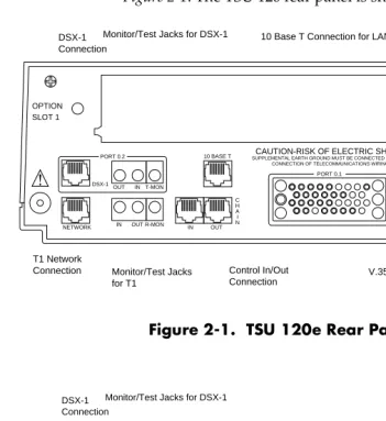
Identification of Rear Panel Layout
The configuration of the rear panel of the TSU 120e is shown in Figure 2-1. The TSU 120 rear panel is shown in Figure 2-2.
Figure 2-1. TSU 120e Rear Panel
Figure 2-2. TSU 120 Rear Panel
OPTION SLOT 1
NETWORK IN OUT
C H A I N IN OUT R-MON
P O W E R 90-120VAC 50/60HZ.2A
CAUTION-RISK OF ELECTRIC SHOCK SUPPLEMENTAL EARTH GROUND MUST BE CONNECTED PRIOR TO
CONNECTION OF TELECOMMUNICATIONS WIRING
10 BASE T
DSX-1 V.35 OUT PORT 0.2 PORT 0.1 IN T-MON
10 Base T Connection for LAN Monitor/Test Jacks for DSX-1
V.35 Connector Power Switch Control In/Out Connection Monitor/Test Jacks for T1 T1 Network Connection DSX-1 Connection OPTION SLOT 1
NETWORK IN OUT
C H A I N IN OUT R-MON
P O W E R 90-120VAC 50/60HZ.2A
CAUTION-RISK OF ELECTRIC SHOCK SUPPLEMENTAL EARTH GROUND MUST BE CONNECTED PRIOR TO
CONNECTION OF TELECOMMUNICATIONS WIRING
DSX-1 V.35 OUT PORT 0.2 PORT 0.1 INT-MON
Monitor/Test Jacks for DSX-1
Chapter 2. Installation
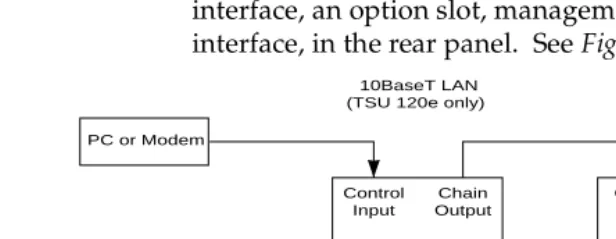
TSU 120 Interfaces
The TSU 120 is equipped with a Nx56/64 data port, a DSX-1 interface, an option slot, management interfaces, and a T1 interface, in the rear panel. See Figure 2-3.
Figure 2-3. TSU 120 Interfaces
Network Interface
The Network Interface (NI) port provides the connection to the T1. This port complies with the applicable ANSI and AT&T standards. For more information see the Wiring section in Appendix C, on page C-1.
Network Test Interface
The IN and OUT test jacks for the network interface provide
intrusive test capability for the incoming T1. By connecting to these jacks with test equipment, the T1 connection will be bro-ken, and the test equipment will terminate the incoming T1.
The R-MON test jack provides a bridged access jack for
non-intrusive monitoring of the incoming T1. When connected to this jack, the test equipment should be configured for a bridged termination.
Nx56/64 Serial Interface (TSU 120e only)
The Nx56/64 provides a serial V.35 port that operates from 56 kbps to 1.536 Mbps. This port provides 511 pattern genera-tion and detecgenera-tion and remote loopback capability.
TSU 120e
PC or Modem
Network
Control Input
Chain Output
NI TSU 120e
Chain Input Chain Output NI Option Option DSX-1 Nx56/64 Nx56/64 DSX-1
PBX V.35 DSX-1 V.35 10BaseT LAN
Chapter 2. Installation
DSX-1 (PBX) Interface
The DSX-1 Interface provides a short haul T1 for a PBX or other equipment. This port complies with ANSI T1.102.
DSX-1 Test Interface
The IN and OUT test jacks for the DSX-1 interface provide
intru-sive test capabilities for the T1 connecting the TSU 120 to the PBX or other customer premise equipment. By connecting to these jacks with test equipment, the DSX-1 connection will be broken, and the test equipment will be terminating the DSX-1 connection from the PBX.
The T-MON test jack provides a DSX monitor access jack for
non-intrusive monitoring of the T1 connecting the TSU 120 to the PBX or other customer premise equipment. When con-nected to this jack, the test equipment should be configured for
a DSX MONtermination.
Chain Port Input
The chain port input provides an EIA-232 input from a PC or a modem for control of the TSU 120. You can also use it as a chain input from another TSU 120 or the TSU 100. For more informa-tion see the Wiring secinforma-tion in Appendix C, on page C-1.
Chain Port Output
The chain port output provides an EIA-232 output to chain con-trol to other TSUs. For more information see the Wiring section in Appendix C, on page C-1.
10BaseT Interface (TSU 120e only)
Chapter 2. Installation
Power Up Testing
When shipped from the factory, the TSU 120 is set to factory default conditions. At the first application of power, the unit automatically executes a memory self-test. A full self-test can be run from the front panel. A passcode and Unit ID may be set using the UTIL MENU.
Self-Test
Upon a power-up, the LCD displays MEMORY TEST NOW TESTING
and the Test LEDs are illuminated. When the self-test is com-pleted with no failures detected, the OK LED lights up and the LCD momentarily displays MEMORY TEST(S) PASSED. If a fail-ure is detected, a list of failfail-ures is displayed in the LCD win-dow.
Initialization
Set User Passcode
The TSU 120 is designed to operate with or without the use of a passcode. The default condition is without a passcode.
If the unit is to be remotely accessed using T-WATCH Pro, you must enter a passcode. When managing a number of units, the passcode can be the same for all the units.
The passcode should be a number easily remembered. Once entered, the passcode is required to access any operation other than viewing. See Change/Set a Passcode on page 6-4 for details.
Set Unit Identification
Chapter 2. Installation
Set Chain Port Input
The TSU 120 can be configured from the chain port input when T-WATCH Pro, SNMP, or the terminal interface are being used. In this case, the chain port baud rate must also be selected.
Chain-In (PC)
The unit can be controlled from an external PC connected directly or via modem to the in port. When using chain-in, the selection of the chain-in port baud rate from 9600 (fac-tory default), 1200, 2400, 19200, or 38400 must be made using the UNIT CONFIGURATION MENU. See Unit Menu on page 5-12 for details.
Unless locked out externally, the front panel can also control the unit.
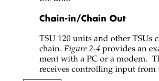
Chain-in/Chain Out
TSU 120 units and other TSUs can be linked together to form a chain. Figure 2-4 provides an example of a chain-in arrange-ment with a PC or a modem. The first TSU 120 in the chain receives controlling input from the PC or modem.
Figure 2-4. Example of Chain-in
Subsequent TSUs in the chain are in a position to intake infor-mation from another TSU. This in-taking of inforinfor-mation from another TSU in the chain is identified as chain-in. The baud rate for the chained units must match that of the first unit.
Unless locked out externally, the front panel can also control the unit.
TSU 120 PC or Modem
Chapter 2. Installation At this point, the Unit Initialization procedure is concluded. If the unit is to be configured remotely, there are no additional items necessary to complete prior to executing remote configu-ration.
The Passcode, the Unit ID, and the Control Port settings are stored in a nonvolatile memory. This ensures they are operable for subsequent power-up sequences.
Power-Up Procedure
Chapter 3
Operation
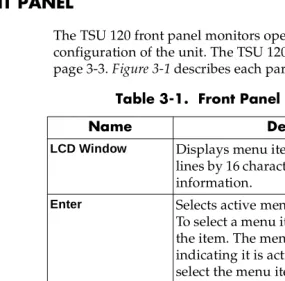
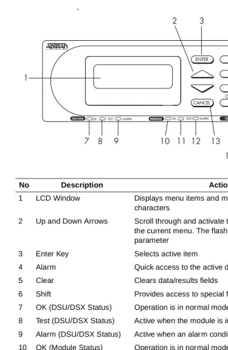
FRONT PANEL
The TSU 120 front panel monitors operation and controls the configuration of the unit. The TSU 120 front panel is shown on page 3-3. Figure 3-1 describes each part of the front panel.
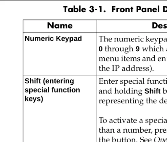
Table 3-1. Front Panel Descriptions
Name Description
LCD Window Displays menu items and messages in two
lines by 16 characters and alarm and status information.
Enter Selects active menu items.
To select a menu item, press the number of the item. The menu item flashes,
indicating it is activated. Press Enter to select the menu item.
Up and Down Arrows
Up and Down Arrows scroll through and
activate the submenu items available in the current menu. When the submenu items are scrolled, the flashing cursor indicates the active parameters.
Cancel Pressing the Cancelkey stops the current
activity and returns to the previous menu. Repeat until the desired menu level is reached. When a submenu item is
Chapter 3. Operation
LED Descriptions
CSU Status
The CSU status LEDs display the operational condition of the network interface located on the controller board in the unit.
Numeric Keypad The numeric keypad contains the numbers
0 through 9 which are used to activate menu items and enter information (such as the IP address).
Shift (entering special function keys)
Enter special function keys by pressing and holding Shift before pressing the key representing the desired character.
To activate a special function key rather than a number, press and holdShift;then the button. See Operation Keys on page 3-5 for a description of the function keys.
If a key is pressed without using Shift, the numbered item becomes active instead of the special function key.
OK (GREEN) Indicates the operation is in the normal mode and no errors have been detected.
TEST (YELLOW)
Indicates that the network interface is operating in a test mode. This includes a self-test or a test loopback. When lighted, this LED also indicates that normal data flow is not occurring on the network interface.
ERROR (RED) Indicates an error such as a BPV, OOF, or CRC.
ALARM (RED) Indicates an alarm condition has been detected. When the alarm condition is no longer valid, the OK LED activates (turns on). To view an alarm condition, select the active alarm menu item or select ALARM by pressing Shift+8. If the alarm conditions have been corrected, the alarm which caused the activation of the Alarm LED can be viewed under the Unit History menu.
Table 3-1. Front Panel Descriptions
Chapter 3. Operation .
No Description Action/Status
1 LCD Window Displays menu items and messages in 2 lines by 16
characters
2 Up and Down Arrows Scroll through and activate the submenu items available in
the current menu. The flashing cursor indicates the active parameter
3 Enter Key Selects active item
4 Alarm Quick access to the active display menus
5 Clear Clears data/results fields
6 Shift Provides access to special function keys
7 OK (DSU/DSX Status) Operation is in normal mode with no detected errors
8 Test (DSU/DSX Status) Active when the module is in test mode
9 Alarm (DSU/DSX Status) Active when an alarm condition has been detected
10 OK (Module Status) Operation is in normal mode with no detected errors
11 Test (Module Status) Active when the module is in test mode
12 Alarm (Module Status) Active when an alarm condition has been detected
13 Cancel Stops current activity and returns to the previous menu
14 Copy Copies last data entered into the current DS0
15 OK (CSU Status) Operation is in normal mode with no detected errors
16 TEST (CSU Status) Active when the network interface is in test mode
17 Error (CSU Status) Indicates errors such as BPV, OOF or CRC
18 Home Returns to the main menu
19 Alarm (CSU Status) Active when an alarm condition has been detected on the
Chapter 3. Operation
DSU/DSX Status
The DSU/DSX status LEDs display the operational condition of the Nx56/64 and DSX-1 parts included in the TSU 120. It also reflects the status of the DBU in the TSU 120e.
Module Status
The module status LEDs display the operational condition of ports installed in the option slots.
OK (GREEN) Indicates the operation is in the normal mode and no errors have been detected.
TEST (YELLOW)
Indicates that one of the interfaces is operating in a test mode. This includes a self-test or a test loopback. When lighted, this LED also indicates that normal data flow is not occurring in at least one of the module ports.
ALARM (RED) Indicates an alarm condition has been detected. When the alarm condition is no longer valid, the
OK LED activates (turns on). To view an alarm condition, select the active alarm menu item or select Alarm by pressing Shift+8. If the alarm conditions have been corrected, the alarm which caused the activation of the Alarm LED can be viewed under the Unit History Menu.
OK (GREEN) Indicates the operation is in the normal mode and no errors have been detected.
TEST (YELLOW)
Chapter 3. Operation
Operation Keys
General Menu Operation
The TSU 120 uses a multilevel menu structure containing both menu items and data fields. All menu operations and data are displayed in the LCD window. The menu items are numbered and can be viewed by scrolling with the Up and Down arrows.
ALARM (RED) Indicates an alarm condition has been detected. When the alarm condition is no longer valid, the OK LED activates (turns on). To view an alarm condition, select the active alarm menu item or select Alarm by pressing Shift 8. If the alarm conditions have been corrected, the alarm which caused the activation of the Alarm LED can be viewed under the Unit History menu.
COPY Used in the DS0 mapping menu operations to copy the last data entered into the current DS0. This key operates without pressing the Shift key.
HOME Returns home to the Main Menu from any menu location.
ALARM Used as quick access to the active alarm display menus. This can be activated while any other menu item is in use. When the Alarm menu is exited, the unit returns to the location of the same menu that was active when Alarm was selected.
CLEAR Used in various menus to clear data/result fields.
DATA FIELD You can edit menu items followed by a colon (:).
DISPLAY ONLY FIELD
You cannot edit menu fields followed by an equal symbol (=). This symbol identifies a field used for value display only.
Chapter 3. Operation
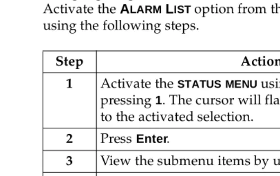
Select and Activate a Menu Item
To choose menu items, place the cursor on the desired menu item by pressing the number corresponding to the menu item or highlighting the menu item with the up and down arrow. Activate the ALARM LIST option from the STATUS MENU by using the following steps.
.
Figure 3-2. Example of Basic Front Panel Menu Tree
Step Action
1 Activate the STATUSMENU using the arrow keys or by pressing 1. The cursor will flash on the number next to the activated selection.
2 PressEnter.
3 View the submenu items by using the arrow keys.
4 Choose an item on the submenu such asACTIVE ALARMS.
5 Select the submenu with the Arrow Keys or by pressing 3.
6 PressEnter.
7 View the Alarm List by using the arrow keys.
1) NI PERF RPTS 2) NI ERRORS
3) ACTIVE ALARMS (ALARM LIST)
4) VIEW HISTORY END OF LIST
1)STATUS 5) PORT STATUS
Chapter 3. Operation
Set the Data Field
You can edit data fields preceded by a colon (:).
Display Only Data Fields
Data fields preceded by an equal (=) symbol cannot be edited. See Figure 3-3.
Figure 3-3. Display and Data Fields
Press Enterto move the cursor to the data field. Use arrows to
Step Action
1 Position the cursor on the submenu item number, and press Enter. The cursor moves to the data field, (to the right of the submenu item name).
2 Using the Arrow Keys, scroll to scan the available value settings. The value settings display one at a time in the data field position.
3 When the desired value is displayed in the data field position, press Enter to set that value. When the value is set, the cursor moves back to the submenu item position indicating the operation is complete.
4 Select another submenu field, or press Cancel to return to the submenu.
5 PressCancel before pressing Enter to void any data changes. The original data value is restored and the cursor returns to the submenu field.
Data Field
Chapter 3. Operation
The equal symbol after LBO in the second line indicates the information that follows is displayed data and cannot be edited.
Exit Any Menu Field Operation Or Display
Press Cancelas many times as needed to return to the desired menu level or pressShift+0 (Home) to return to the main menu.
Data Port Identification
When configuring the unit, menu selections will include options from data port submenus. Selecting data ports is neces-sary because the TSU 120 uses a slot-port method to identify which data port the menu item is referencing. If a module con-taining a PBX DSX-1 option card with an Nx56/64 plug-on interface is installed in the option slot, it would be designated as:
DSX-1 Passthru=1.1
Where slot=1 and port =1.
The DSX-1 is located in the option slot and is the first port in that slot.
Nx56/64=1.2
Where slot=1 and port=2.
The Nx is located in the slot and is the second port in that slot.
The ports that are built into the TSU 120 are referenced as Slot
0. TheNx56/64 would be designated as 0.1 and theDSX-1
Chapter 3. Operation
Front Panel Menu Structure
The TSU 120 uses a multilevel menu structure containing both menu items and data fields. All menu operations and data dis-play in the LCD window.
The opening menu is the access point to all other operations. Each Main menu item has several functions and submenus to identify and access specific parameters.
The front panel LCD of the Main menu contains the following options
Status
The Status menu displays all relevant information for the net-work and DTE interfaces. For detailed information on status options, see Chapter 4, Status Menu on page 4-1.
Config (Configuration)
The Configuration menu displays and sets the TSU 120 opera-tional configuration, including all network interface parame-ters, the allocation of the DS0s, and the port parameters. For detailed information on configuration options, see Chapter 5, Configuration Menu on page 5-1.
Util (Utilities)
The Utility menu displays and sets system parameters. For detailed information on utility options, see Chapter 6, Utility Menu on page 6-1.
Test
The Test menu initiates different types of unit tests and dis-plays test results in the LCD window. For detailed information on test options, see Chapter 7, Test Menu on page 7-1.
1=STATUS 3=UTIL
Chapter 3. Operation
Alternate Methods of Control
T-WATCH Pro (ADTRAN PC Program)
T-WATCH Pro is the ADTRAN PC control program. It provides complete control over the configuration of the TSU 120 using a graphical interface. The T-WATCH Pro program displays the same status and performance data as the front panel LCD. This data is displayed in the form of tables and graphs.
The T-WATCH Pro program has the following capabilities:
• Interfaces with a modem which permits dialing into a re-mote TSU 120 location to configure the unit or read the sta-tus or performance of the unit.
• Receives traps from any TSU product.
• Records and creates display performance data over a 30-day period.
• Accesses units via the local area network (TSU 120e only).
T-WATCH Pro/LAN Connection
To set up the TSU 120 to work with T-WATCH Pro over the LAN, follow these steps:
Step Action
1 Set the Unit ID using the front panel. See Unit ID on page 6-4 for details.
2 Set CONTROL PORT interface to NORMAL using the
Front Panel
3 Configure the IP ADDRESS, DEFAULTGATEWAY, and SUBNETMASKusing the front panel.
Chapter 3. Operation
T-WATCH Pro/EIA-232 Connection
To set up the TSU 120e to work with T-WATCH Pro over a direct EIA-232 connection, follow these steps:
SNMP
The ADTRAN TSU 120 supports the Simple Network Manage-ment Protocol (SNMP) through the chain-in (SLIP) interface. The TSU 120e offers a 10BaseT connection which also supports SNMP. For more information on SNMP see Appendix A, Under-standing SNMP on page A-1.
To use SNMP via 10BaseT (TSU 120e only), follow these steps:
Step Action
1 Set the Unit ID and set a passcode using the front panel. See Unit ID on page page 6-4 and Set a Passcode on page 6-4 for details.
2 Set the control port rate to the same setting as the PC Com port.
3 Connect the PC Com port to the chain-in port on the TSU 120 using the DB25 adapter and modular cable provided.
4 Follow the installation instructions for T-WATCH Pro to start the program and to connect to the unit.
Step Action
1 Set CONTROL PORT to NORMAL.
2 Set the IP ADDRESS, DEFAULTGATEWAY, and SUBNET MASK.
3 The appropriate MIB browser must be loaded into the Network Management Station (available on the ADTRAN webpage at http://www.adtran.com).
Chapter 3. Operation
To use SNMP via SLIP port, follow these steps:
Terminal Mode
The TSU 120 provides the front panel menus to a VT 100-type terminal. This mode can be used to configure and monitor the unit. Initiate this mode by keying in <CTRL> PTT on the termi-nal once it is connected to the chain-in port. For more informa-tion on this method of control, see Chapter 8, Telnet/Terminal Menus on page 8-1.
TELNET
To connect to the TSU 120 via TELNET, follow these steps.
Only one TELNET session can be active at one time.
Step Action
1 Set CONTROL PORT to SLIP.
2 Set the IP ADDRESS. The DEFAULTGATEWAY, and SUBNETMASK are not used in SLIP.
3 The appropriate MIB browser must be loaded into the Network Management Station (available on the ADTRAN webpage at http://www.adtran.com).
4 The MIB browser issues SNMP gets/sets to the TSU 120e.
Step Action
1 Before attempting to connect via TELNET, first define the IP address, the default gateway, and the subnet mask using the front panel.
2 When you begin the TELNET session, you will be prompted for a password. The default password is
ADTRAN.
3 You can change this password using the Management submenu. See Default Unit Passcode on page 8-7 for more information.
Chapter 4
Status Menu
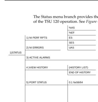
The Status menu branch provides the ability to view the status of the TSU 120 operation. See Figure 4-1.
Figure 4-1. Complete Status Menu Tree
Menu flow is normally depicted from left to right. Arrows on the lower right of the screen indicate the direction of scrolling to use to view additional menu items. At every level of the menu, pressing Cancelreturns the system to the previous menu
%AS
%EF
1) NI PERF RPTS ES
SES
2) NI ERRORS UAS
1)STATUS
3) ACTIVE ALARMS (ALARM LIST)
END OF LIST
4 )VIEW HISTORY (HISTORY LIST)
END OF HISTORY
1) DTE DATA/CLOCK
5) PORT STATUS 0.1 Nx56/64 2) DTE STATUS
3) PORT RATE
4) DBU DATA/CNTR (TSU 120e)
5) DBU CONTRL (TSU 120e)
6) DBU STATUS (TSU 120e)
6) REMOTE PORT
0.2 DSX-1 DSX-1 ERRORS
7) CLEAR PORT ALM
(OPTION LIST)
Chapter 4. Status Menu
Network Performance Reports (NI PERF RPTS)
The Network Interface Performance Reports display the user copy of the performance data. The TSU 120 maintains this per-formance data on the network in compliance with ANSI T1.403 and AT&T document TR54016. The data displayed is data accu-mulated over the last 15 minutes and over the last 24 hours.
Use the scroll keys to access the complete display of the follow-ing report fields, as shown in Figure 4-2:
Figure 4-2. Network Interface Performance Report
If insufficient time has passed to collect data, NA displays. Continue with standard operating procedures to exit the dis-play.
When this menu is active, performance data can be cleared by pressingClear (Shift+9)on the keypad. Only the user copy of the performance data is cleared.
%AS Percentage of available seconds
%EF Percentage of error-free seconds
ES Number of errored seconds (1 or more errors/second
SES Number of severely errored seconds (more than 320 errors/second)
UAS Number of unavailable seconds (10 or more consecutive seconds)
15 Minutes 24 Hours
Chapter 4. Status Menu Since only the user ’s copy of performance data is cleared by the TSU 120, the data displayed here might be different from the data sent to the network as PRM data.
Network Interface Errors (NI ERRORS)
The NIERRORS submenu displays the types of errors the Net-work Interface (NI) detects. A blinking CSU error LED indi-cates that network errors are detected.
The asterisk (*) above an item indicates the type of errors detected. The error types are the following:
Active Alarms
This menu item displays a list of current alarms (ALARM LIST) reported by either the base controller or any of the ports. If no alarms are current, using this menu item displays End of List.
This display includes two lines of text. The top line is the alarm source. The bottom line is the alarm message. See Figure 4-3 on page 4-4. A list of alarm messages is found in Appendix C, TSU 120 System Messages on page C-1.
In addition to normal menu operation, you can also access this menu item with the Alarm function (Shift+8) on the keypad. If one or more of the Alarm LEDs are illuminated, an alarm is present. Pressing Cancel returns to the previous menu item. CRC CRC-6 bit errors based on the FDL. This is valid
only in ESF mode.
BPV Bipolar violations.
XS0 Excess zeros.
Chapter 4. Status Menu
Figure 4-3. Display of Alarm Message
View History
This menu item both displays and clears the accumulated sta-tus changes of the unit.
View History displays a history of the first 20 status changes in the unit, including the date, time, and type of change. The unit also records for viewing, the date and time an alarm became active and inactive, as well as the date and time of test activa-tion and deactivaactiva-tion.
To clear the View Historydisplay, press Clear (Shift+9)with the View History menu active.
Port Status
Port Status displays the signals monitored on the data ports. For example, the Nx/DBU interface monitors the RTS, CTS, and RD, along with other signal lines. When a port is selected, the LCD indicates if the signal is present.
The base Nx interface offers the status screen listed in this sec-tion. When using other option cards, refer to the appropriate separate manual for a definition of any status screens offered.
The Port Status of Nx/DBU is examined as an example of how to use this item. The DBU feature is available only in the TSU 120e.
Alarm Source
Chapter 4. Status Menu
0.1 Nx56/64 Menu Items
DTE Data/Clock
An asterisk (*) indicates an active status of the following lines.
DTE Status
An asterisk (*) indicates an active status of the following lines:
Port Rate
The port rate displays the current setting of the Nx port. Con-tinue with standard operating procedures to exit the display.
DBU Data/CNTRL (TSU 120e only)
An asterisk (*) indicates an active status on the following lines: TXD Transmit data from the DTE
RXD Receive data toward the DTE
XS0 Excess Zeros from the DTE
LCK Lock Status of the phase locked loop
RTS Request to send from DTE
CTS Clear to send to DTE
DCD Data carrier detect to DTE
DSR Data set ready to DTE
TXD Transmit data to the DCE
RXD Receive data from the DCE
DCD Data carrier detect from the DCE
Chapter 4. Status Menu
DBU Contrl (TSU 120e only)
DBU Status (TSU 120e only)
0.2 DSX-1 Menu Items
DSX-1 Errors
RTS Request to send to DCE
CTS Clear to send from the DCE
DTR Data terminal ready to the DCE
DSR Data set ready from the DCE
DBUSECS Total seconds in current DBU session
INDBU YES/NO indication of active DBU status
CRC An asterisk displays under the CRC if there are CRC errors in extended superframe format (ESF) mode. If the DSX-1 plug-on board is configured for D4 Frame format, the LCD displays n/a.
BPV An asterisk displays under the BPV if the DSX-1 plug-on board detects bipolar violations.
SLIP An asterisk displays under the SLIP if the DSX-1 plug-on board detects frame slips. This is caused by multiple clock sources in the application.
Chapter 4. Status Menu
Remote Port
Remote Port displays the status of activity on the control-in remote port. This is useful for troubleshooting communication sessions, and for verifying cabling.
Clear Port Alarm (Clear Port Alm)
Clears the Link Failed alarms on option modules that have been removed from the TSU 120 chassis.
ENET Status (TSU 120e only)
RX Characters received at remote port
ID Unit ID received at remote port
CRC Correct CRC received
PC Correct passcode received
TX Characters transmitted from the remote port
TX Indicates that data is being transmitted from the 10BaseT port.
RX Indicates that data is being received by the 10BaseT port.
LNK Indicates the current status of the 10BaseT link integrity test. This should always be on when the unit is connected to a functional 10BaseT hub.
Chapter 5
Configuration Menu
The CONFIGURATION MENU sets the TSU 120 operational config-uration, including all network interface parameters, the alloca-tion of the DS0s, and the port parameters. See Complete Configuration Menu on page 5-2.
Chapter 5. Configuration Menu
Figure 5-1. Complete Configuration Menu
1) FORMAT 1) CTL PORT RATE
2) CODE 2) TRAPS
3) YEL ALARM 3) ACCESS
4) XMIT PRM 4) INIT MODEM
5) TIMING MODE 5) CONTROL PORT
1) NETWORK (NI) 6) SET LBO 6) IP ADDRESS
7) INBAND LPBCK ALARM REPORTS 7) SUBNET MASK
8) BIT STUFFING ALARM FORMATS 8) DEFAULT ROUTER
9) TR-08 OPTIONS BPV THRESHOLD 9) SLIP RATE
2) UNIT A) SLIP FLOW CTL
B) PROXY TRAPS
3) MAP XCHNG OFF
AUTO
4) MAP IN USE: A(B) 1) MAP A @:HH:MM
2) MAP B @:HH:MM
3) CONFIG 5)DS0 MAP A 1) COPY A > TEMP
2) CREATE TEMP 1) DSO RATE
1) COPY B > TEMP 3) REVIEW MAP A 2) TX CLK CNTRL
2) CREATE TEMP 4) REVIEW TEMP 3) DATA
6) DS0 MAP B 3) REVIEW MAP B 5) EDIT TEMP 4) CTS
4) REVIEW TEMP 6) APPLY TEMP > A 5) DCD
5) EDIT TEMP 6) DSR
6) APPLY TEMP > B 0.1 Nx56/64 Config 7) “0” INHIBIIT
8) INBAND MODE
7) PORT CONFIG Nx56/64 (0.1) 9) TX CLK SOURCE
THIS SECTION APPLIES ONLY TO THE TSU 120e
DBU Config 1) BACKUP MODE
2) BACKUP ON
02. DSX-1 1) FORMAT 3) PATTRN VERIFY
(OPTION PORTS) 2) CODE 4) BACKUP DELAY
3) YELLOW ALARM 5) RESTORE DELAY
4) LINE LENGTH 6) RETRY DELAY
5) INBAND LPBACK 7) NUM RETRIES
6) ROB BIT SIGNL 8) BACKUP TESTING 1) BACKUP TEST
9) WKEND LOCKOUT 2) TEST HOUR
A) ENABLE HR 3) TEST DAY
B) DSABLE HR
Chapter 5. Configuration Menu
NETWORK (NI)
This menu item accesses the configuration of parameters asso-ciated with the network interface in the base unit. There are nine submenu items that include setting the format, the line build out (LBO), and the timing mode. Submenu items do not include setting the parameters which may be necessary for a secondary interface (DSX-1 Passthru, etc.).
Network (NI) Menu Items
The menu items are:
Menu Item Description
FORMAT Sets the frame format for the NI.
Choices: D4, ESF, and SLC96
D4 is equivalent to superframe format (SF).
CODE Sets the line code for the NI.
Choices: AMI and B8ZS.
YEL ALARM Enables and disables the transmitting of yellow alarms.
Choices: ENA and DISA.
XMIT PRM Enables and disables the sending of PRM data on the facility data link (FDL). The PRM data continues to be collected even if XMITPRMis disabled (possible only with ESF Format).
Choices: Off and On.
TIMING MODE
Selects the clock source for transmission toward the network from the NI. See TSU 120 Clock Sources on page 5-5 for more information
Chapter 5. Configuration Menu
SET LBO Selects the line build out for the network interface. In AUTOMODE, the TSU 120 sets the LBO based on the strength of the receive signal and displays the selected value.
Choices: 0.0 dB, 7.5 dB, 15 dB, 22 dB, Auto.
In order to activate the -36 dB receiver sensitivity, the LBO should be set toAUTO.
This feature is useful in a point-to-point application where no network elements are involved. If a network element such as a Smart Jack is installed on the circuit, the LBO should be set to 0 dB.
INBAND LPBCK
Sets unit to accept or reject the network interface loop-up and loop-down codes as defined in ANSI T1.403.
Choices: Accept, Reject.
BIT
STUFFING
When enabled, bit stuffing causes the TSU 120 to monitor for ones (1s) density violations and insert a one (1) when needed to maintain 1s at 12.5 percent.
Choices: Enable, Disable.
TR-08 The TR-08 submenu configures the unit for TR-08 applications. The submenu items and their descriptions follow.
Alarm Report
Enables and disables the transmitting of alarm reports. Choices: SEND ALARMS, DISABLE ALARMS
Alarm Format
Sets the alarm frame format to 13 frames or 16 frames. Choices: ORB-13, ORB-16
BPV Threshold
Sets the threshold for BPVs to trigger an alarm. Choices: 10-4, 10-5, 10-6
Chapter 5. Configuration Menu
TSU 120 Clock Sources
The TSU 120 is operable from various clock sources permitting it to perform properly in many different applications. Set the network interface clocking options with the clocking options set by the Network (NI) Configuration menu options.
The following clock source options are available:
• Network
• Base DSX-1 Timing
• DTE Timing
• Internal Timing • Secondary Timing • Normal (CSU) Timing
• U-BR1TE
Chapter 5. Configuration Menu
Network Timed
The network is the source of timing. The received data clocking is looped back to the network where it is used to determine the transmission timing. This option is also referred to as loop timed as the transmission clock is derived from the received clock. See Figure 5-2.
.
Chapter 5. Configuration Menu
Base DSX-1 Timing
The PBX is the source of timing. The TSU 120 uses the clock derived by the Base DSX-1 interface for transmission timing. See Figure 5-3.
Figure 5-3. DSX-1 Timed Clock Source
DTE OSC
( O P T I O N )
Network Interface T1 XMIT
T1 Receive
( D S 1 )
Nx56/64
DTE CLOCK
DSX-1
Chapter 5. Configuration Menu
DTE Timing
The DTE is the source of timing. The TSU 120 uses the incom-ing DTE clock to determine the transmission timincom-ing. This is typically used in applications where it is necessary to have the DTE as the primary clock source, (such as limited distance line drivers). See Figure 5-4.
Figure 5-4. DTE Timed Clock Source
DTE OSC
( O P T I O N )
Network Interface T1 XMIT
T1 Receive ( D S 1 )
Nx56/64
DTE CLOCK
DSX-1
Chapter 5. Configuration Menu
Internal Timing
The TSU 120 is the source of timing. The TSU 120 is configured to use its own internal oscillator as the source of timing. Appli-cations include private line driver circuits where one end is set to network and the other to internal. See Figure 5-5.
Figure 5-5. Internal Clock Source
DTE OSC
( O P T I O N )
Network Interface T1 XMIT
T1 Receive
( D S 1 )
Nx56/64
DTE CLOCK
DSX-1
Chapter 5. Configuration Menu
Secondary Timing
The secondary interface is the source of timing. The TSU 120 uses the clock derived by the secondary interface for transmis-sion timing and the receive signal timing. See Figure 5-6.
Either a DSX-1 Option Module or a Drop and Insert Option Module must be installed in the TSU 120 for this mode to func-tion.
Figure 5-6. Secondary Timing
DTE OSC
Secondary Interface
(SI)
( O P T I O N )
Network Interface (NI) T1 XMIT
T1 Receive
( D S 1 )
Nx56/64
DTE CLOCK
DSX
PBX
Chapter 5. Configuration Menu
Normal (CSU) Timing
In the Normal (CSU) Timing mode, the Receive Clock is derived from the Network Interface while the Transmit Clock is derived from the PBX or other alternative timing source, con-nected to the Secondary Interface (e.g., Drop and Insert or DSX-1). See Figure 5-7.
This timing option is the same as that typically used for CSUs. This is the preferred mode for use with a PBX application.
Figure 5-7. Normal (CSU)
The network interface and secondary interface clocking options are set by using the Network (NI) Configuration menu options. Either a DSX-1 Option Module or a Drop and Insert Option Module must be installed in the TSU 120 for this mode to func-tion.
U-BR1TE
The U-BR1TE timing selection works like Normal (CSU) except that timing is derived from the U interface on port 1.1.
Network Interface (NI)
Secondary Interface
(SI)
Chapter 5. Configuration Menu
Unit Menu
The Unit menu changes the baud rate of the chain in port and the setup of the dial out port. The menu items are:
Menu Item Description
CTL PORT RATE
Sets the baud rate for communication with the PC or modem.
Choices: 1200, 2400, 9600, 19200, and 38400 kbps
TRAPS Enables or disables the transmission of trap messages.
Choices: Enable, Disable
ACCESS Sets the method of connection from the TSU 120 to T-WATCH Pro/SNMP
Choices:
Direct - Used if connected directly to the PC.
Dial - Used when connection is through a modem. The dial string is entered from T-WATCH Pro/SNMP.
INIT MODEM Allows you to choose an industry standard or a custom initialization string for a modem connected to the control port.
Choices: Industry Standard, Custom Initialization String
CONTROL PORT
Selects the TCP/IP physical interface; Normal, using the 10BaseT Ethernet or SLIP using the EIA-232 serial port (10BaseT is only available in the TSU 120e).
Choices: Normal, SLIP
Chapter 5. Configuration Menu
IP ADDRESS This is the IP address that uniquely identifies the TSU 120 on a TCP/IP network.
This address is composed of four decimal numbers, each in the range of 0 to 255, separated by periods. This value is used for either the 10BaseT Ethernet or SLIP interface, depending on the IP interface setting
(10BaseT is only available in the TSU 120e).
SUBNET MASK
This defines which part of a destination IP address is the Network number. It is used along with the TSU 120 IP address to determine which nodes must be reached through the default IP Gateway. This value is ignored when the IP interface is set to SLIP.
DEFAULT ROUTER
All IP Packets destined for nodes not on the TSU 120 unit’s local network are not forwarded through this IP address. Normally, this address defines a router connected to the TSU 120 unit’s local network. This value is ignored when the IP interface is set to SLIP.
SLIP RATE This sets the baud rate for the Chain-In port when used as the SLIP connection for SNMP management.
Choices: 1200, 2400, 4800, 9600, 19200, 38400 Kbps
SLIP FLOW CTL
This is used to activate flow control on the Chain-In port when used as the SLIP
interface. Hardware mode uses RTS and CTS.
Choices: None, Hardware
PROXY TRAPS This determines whether or not traps will be forwarded from units being “proxied” for.
Choices: Enable, Disable
Chapter 5. Configuration Menu
Map Exchange (Map Xchng)
The MAP EXCHANGEmenu enables and sets the automatic time of day map switch. The unit provides selection of the hour, minute, and seconds for the map switching to take place.
The menu items are:
1. Scroll to selectAUTOto enable or OFFto disable the Automatic Map Change feature.
2. Press Enter to activate the selection.
3. When AUTO is selected, the unit displays the screens to set times for switching.
4. After editing Map A, press Enter to record the Map A settings and activate the selection fields for Map B. 5. Use the same operation to edit switching time for
Map B.
When ESF is used with an FDL channel between units, the units automatically coordinate the automatic map switch by sending a map switch command from end-to-end over the FDL. Only one end needs to be set to Auto for this to work.
Map In Use: A(B)
The MAPIN USEmenu item controls the DS0 map the TSU 120 uses and displays the map in current use.
Menu Item Description
OFF Indicates the map in use does not change
(disabled).
Chapter 5. Configuration Menu
DS0 Map A and DS0 Map B
The DS0 maps designate which DS0s are assigned to which port. See Figure 5-8. There are three maps, DS0 MAP A, DS0 MAP B, and the TEMPORARY (TEMP) MAP.
Figure 5-8. DS0 Map Designations
Map A and Map B are the current maps the TSU 120 uses. The Temp map generates a map before putting it into use.
You can copy Map A to Map B by copying the Map A into the TEMP map. Then apply (write) the TEMP map into Map B.
The menu items are:
Menu Item Description
COPY A (B) >TEMP This copies the current map (A or B) into a Temp Map area. This permits modification without disturbing the existing map. When the modifications are completed, the Temp Map is written to currentMAPA (B) by selecting Apply.
CREATE TEMP This creates a map by defining a port or Idle for all DS0s. When CREATETEMPis first selected, all DS0s are set to Idle. See DS0 Map Example on page 5-16 for more information.
REVIEW MAP A(B) Permits a quick review of the number of DS0s assigned to each port and the number of unassigned DS0s (Idle or TST) as defined
T E M P
Chapter 5. Configuration Menu
DSO Map Example
A sample selection follows:
DS0: 01 to 24
PORT: IDLE, TST, + option module ports
TST designates which DS0s are used for QRSS testing when activated under the TESTMENU. When not used for testing, the TST designation is identical to Idle.
REVIEW TEMP This menu item is operated the same for the Temp Map as is 3)REVIEWMAPAor MAPB.
EDIT TEMP The map in the Temp file can be edited to whatever configuration is desired. If Map A had been copied into the Tempfile, then after editing, the Temp file could be applied to MAPAor MAPB. The menu operation is identical to 2) CREATETEMP with the exception that the existing port selections display.
APPLY TEMP> A(B) Writes the Temp map into MAPA. Apply is usually the last step in updating a map and is accessed automatically at the end of editing or creating a temporary map. Currently, it can be bypassed by selecting another menu choice.
Chapter 5. Configuration Menu With the cursor onCREATETEMP, press Enter. The unit displays the selection screen with the cursor positioned on the first selection DS0 number. See Figure 5-9.
Figure 5-9. Create Temp Selection Screen
1. Use either the Arrow Keys or Numbers to enter the DS0 number (do not mix the use of the keys).
2. Press Enter to complete the selection and move the cur-sor to Port, the next field.
3. Scroll to select the port which is dependent on the installed option card.
4. Press Enter to complete the selection and move the cursor back to the DS0 field.
5. With the cursor on the DS0 field, the DS0 number can be incremented or decremented by scrolling.
6. Press Copy to place the contents of the last DS0 in the new DS0 number.
7. When all entries are complete, press Cancel to move the cursor to the last of the submenu choices,6)APPLY. 8. Either apply the newly created DS0 map or press
CANCELto return to theDS0 MAPA (B) submenu choices.
Selecting Apply will not disrupt the operation of unmodified ports.
Select DS0 Number
Chapter 5. Configuration Menu
Port Configuration (Port Config)
Port Configuration selects and configures the parameters asso-ciated with any data port in the unit. For example, parameters for the DSX-1 (PBX) interface are set through this menu. The items that can be set depend on which option module is installed. The list of option ports will