An Experimental Study on Effect at the Work
Piece Surface Has On Fluid Delivery during
Grinding Process
Mohd Rosli Saad1, Zabidi Saad2
1,2
Mechanical Engineering Department, Seberang Perai Polytechnic Penang, Malaysia
Abstract
This analysis aims to study on effect at the work piece surface has on fluid delivery during grinding process. Two coolant delivery methods were used in identify in this experiment. There are new coolant device and conversional coolant device. The surface roughness of the wheel is important in quantifying coolant flow through the grinding zone as well as how much coolant penetrates to grinding zone. Surface roughness test was used to get the result. Result from experiment with different depth of cut and different quantities of coolant fluid passing through the grinding zone are presented. Nozzle method (CCD) in this experiment was found not enough fluid and not distributed to the wheel carried to grinding zone. NCD was shown to affect the volume of coolant passing beneath the grinding wheel.
Keywords: grinding zone, coolant, surface roughness, surface burning, fluid delivery.
1. Introduction
Grinding is the collective name for machining process which utilizes hard abrasive grains as the cutting medium to remove material from a workpiece. Grinding is a main manufacturing process which accounts for about 20-25% of the total expenditures on machining operations in industrialized countries. Grinding is traditionally used as a final machining process in the production of components requiring smooth surface and fine tolerances. Grinding is expensive, it is responsible for up to 80% of the price of the finished product, this is the main cause for inhibiting a wider application of ceramic machine components. To achieve cost effectiveness, machining technology must aim at optimizing the complete grinding system. The grinding machine is used for roughing and finishing flat, cylindrical, and conical surface, finishing internal cylinders or bores, forming and sharpening cutting tools, snagging or removing rough projections from casting and stampings and cleaning, polishing and buffing surface. Once strictly a finishing machine, modern production grinding machine are used to complete roughing and finishing of certain classes of work.
The benefits of cutting fluid are generally recognized throughout industry, despite this, cutting fluid are often treated as an afterthought and given
insufficient attention. It is found that the boundary layer of air around wheel deflects most of the grinding fluid away from the grinding zone. A better understanding is required of the hydrodynamics of cutting fluid delivery and ways to optimize it. A cutting fluid has three main functions when applied to the grinding process. These are, bulk cooling of the workpiece, the flushing away of swarf and dislodged wheel grits and lubrication. Bulk cooling and flushing are reasonably understood but lubrication effect of the cutting fluid are less clear. It is generally accepted that cutting fluid lower the grinding zone temperature due to lubrication, which is reduce wheel dulling, rather than by removing heat from the grinding zone. By reducing wheel dulling, friction and hence power is reduced so that the heat generation is limited. Bulk cooling and flushing can active even though very little fluid enters the contact region and although a large volume may not be necessary to active this purpose, fluid delivery will be ineffective if no fluid enters the grinding zone. This investigation was aimed at achieving a better understanding of effect and coolant flow at the grinding zone has on fluid delivery.
2. Methodology
2.1 Design and Development of New Coolant Device
To fulfill the objective of this research, some conditions of the device must be considered to achieve desired performance in the new design. The design of the new device is based on the design conditions below:-
1. The gap between grinding wheel and sliding device is small and have to make sure that the flow can go according to the shape of wheel 2. The coolant flow are always reach
accordingly to the wheel surface
3. The coolant supplied from the device flow straightly go to the grinding surface
4. In the process to build up the new coolant device, some important steps involved as below:-
• Designing the coolant device
• Dimensioning and drawing the new coolant device using AutoCAD software to get the accurate and precise dimension and the most
important is that the dimension must fit the grinding machine for assembling it
ISSN (Online) 2348 – 7968 www.ijiset.com - Few materials are to be taken into
consideration and to selection the material such as, aluminum plate, carbon steel plate, mild steel plate, Perspex and etc.
- Perspex is the most suitable material due to its transparency, low cost, easy to shape, light weight and easy to assemble.
• Cutting and shaping
- Perspex is cut using power saw machine, for the curve part of the design, the Perspex is being shape using hot air blower and for the hollow part is using drilling machine.
• Finishing the surface of Perspex using milling machine to uniform surfaces and to get a smooth surface we use abrasive paper added with water.
• Assembling the Perspex using chloroform and to assemble the device to grinding machine using screws.
2.2 Materials for the New Coolant Device
The materials that being selected for the new coolant device:-
1. The body structure = 0.3cm Perspex
2. Coolant joint = rubber tube pipe 1.5cm of diameter
3. Screw for joined device to surface grinding machine
4. Chloroform as a glue
2.3 Measurement of the Surface Roughness
Various instruments are available for the roughness measurement. The measurement technique can be divided into two broad categories:-
1. a contact-type in which during measurement a component of the measurement instrument actually contacts the surface to be measured 2. a non-contact type
A contact-type instrument may damage surfaces when used with sharp stylus tip, particularly soft surfaces. For these measurements, the normal loads have to be low enough so that the contact stresses do not exceed the hardness of the surface to be measured. There exist a number of other techniques that have been neither demonstrated in the laboratory nor never commercially used in specialized applications. Generally they are divided into six categories based on the physical principle involved:-
• mechanical stylus method
• optical method
• scanning probe microscopy (SPM) methods
• fluid methods
• electrical method
• electron microscopy methods
We choose mechanical stylus method for measuring the grinded workpiece surface roughness and the measurement conducted in Metrology lab. The general procedure is such that a diamond-tipped stylus is mechanically moved over the surface and the deflections of the stylus are converted into electrical signals are then amplified electronically and passed through a CPU which indicates the appropriate graph for further analysis using a specified software.
3. Experiment of Set-Up
3.1 Coolant Specifications
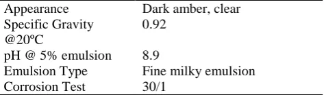
The coolant used throughout the grinding process is the shell Dromus Oil BL, which is emulsifiable mineral cutting oil which biocide using in a lots of manufacturing process, such as tapping, drilling, milling, planning, shaping, grinding and etc. the Dromus Oil BL has been specifically developed as a high quality, multipurpose water-mix metalworking fluid which produces superior quality high oil content (milky) emulsions on dilution with water.
Table 1 : Properties of The Coolant – Dromus Oil BL
Appearance Dark amber, clear Specific Gravity
@20ºC
0.92
pH @ 5% emulsion 8.9
Emulsion Type Fine milky emulsion Corrosion Test 30/1
3.2Description of experiment
3.2.2 Test surface quality
workpiece material
Low Carbon Steel
Wheel material Aluminum oxide (WA 48k 8V 1A) Depth of cut 10µm, 20µm, 30µm, 40µm, 50µm Methodof
delivery
Conventional nozzle and NCD
wheel speed 3306 RPM ( 17.78 m/s) measured using tachometer
wheel width 30mm wheel radius 128mm table speed 0.12 m/s
Coolant used Shell Dromus oil BL
Table 2: Specification and Parameters for Surface Grinding Machine
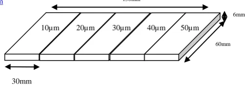
The apparatus set-up of the experiment as shown in fig.1and fig. 2 below consist of grinding wheel of grinding machine table assembled with coolant system and low carbon steel as workpiece. Three workpiece are prepared separated part on the workpiece to proff the different depth of cut. See fig.4. Each part of the workpiece is used for different grinding depth.
Fig. 1 Layout of the apparatus set-up for experiment
Fig.2 Experiment setup in photograph
Fig.4 Workpiece for experiment
The coolant device used in the experiment is conventional coolant device and new coolant device. Before experiment going on, to make sure the grinding process start in a good condition, the workpiece should be in perfectly linear. Make sure also that on the table, the surface is clean and there are no crapper or rusty on it.
The experiment will start with constant coolant flow rate of 0.08L/s. The grinding wheel go through the workpiece in specific depth of cut one time and than proceed to the next part of workpiece with the different depth of cut.
After the grinding process was finish, we further to the analysis of the surface texture for grinded workpiece was conducted by using Taylor Hobson Surface Roughness’ Machine to get specific surface roughness measurement for comparison analysis. Table 3 below present the specification and parameters of Taylor Hobson Surface Roughness Machine.
Instrument Taylor Hobson Surface Roughness Machine (code 112-2617-01)
Tracing length 5.6mm Measurement Speed 0.5mm/s
Stylus shape Standard with size 2μm radius Measurement angle 90˚
Parameter used Ra, Rz, Rt
Table 3: Surface Roughness Instrument and Specification
4. Result and Discussion
Grinding test was performed to establish whether the effect of cutting fluid quantity passing through the grinding zone, on workpiece quality, could be detected. Three trials were performed, three for each coolant device, consisting of three workpiece each. The efficiency of the process was evaluated in surface texture.
60mm
30mm
6mm
50µm 40µm
30µm 20µm
10µm
New coolant device
ISSN (Online) 2348 – 7968 www.ijiset.com CCD S u rf ac e R o u g h n es s ( µ m)
Depth Of Cut
10 µm 20µm 30µm 40µm 50µm
Test 1 Ra 0.5328 0.6714 0.6953 0.7702 0.7887 Rt 4.7555 6.7646 5.7008 5.1430 5.4289 Rz 3.7473 4.5789 4.8281 4.4733 4.5010
Test 2 Ra 1.2404 1.3180 1.3865 1.4250 1.5291 Rt 12.340 19.274 9.6573 10.222 8.4355 Rz 8.0278 9.5077 7.6371 7.7077 7.5485
Test 3 Ra 0.4934 0.5692 0.6121 0.6316 0.7236 Rt 4.2077 4.5148 6.4381 5.3511 5.8171 Rz 3.5866 3.9854 4.5901 4.4095 4.5026
averag e
Ra 0.7555 0.8286 0.8983 0.9422 1.0138 Rt 7.1010 10.184 7.2654 6.9053 6.5605 Rz 5.1205 6.024 5.6851 5.5302 5.5172 Table : 4 Surface roughness data of 1st Experiment
NCD S u rf ac e R o u g h n es s ( µ m)
Depth Of Cut
10 µm 20µm 30µm 40µm 50µm
Test 1 Ra 0.6945 0.9087 0.9556 1.1262 1.0423 Rt 8.3137 8.0980 8.3637 9.1822 10.864 Rz 5.4855 5.9012 5.9841 8.3091 8.3482
Test 2 Ra 0.3781 0.3718 0.5187 0.6031 0.7666 Rt 2.8144 3.5567 3.8978 4.9577 7.6283 Rz 2.4697 2.5656 3.5253 3.9770 5.7367
Test 3 Ra 0.3259 0.5026 0.5403 0.8482 0.8961 Rt 3.1726 4.6740 8.4694 12.717 10.666 Rz 2.5496 3.5090 5.0145 6.4141 6.1526
averag e
Ra 0.4660 0.5943 0.6715 0.8592 0.9016 Rt 4.7669 5.4429 6.9103 8.9524 9.720 Rz 3.5170 3.9919 4.8413 6.2334 6.7458 Table: 5 Surface roughness data of 2nd Experiment
Flow rate
0.04L/s 0.06L/s 0.08L/.s
NCD S u rf ac e R o u g h n es
s Ra 0.7869 0.7168 0.6561
Rt 10.4014 5.9750 6.0230 Rz 6.1433 4.8953 4.3496
CCD Ra 0.7643 0.7224 0.6877
Rt 5.9660 5.2498 5.5985 Rz 5.0447 4.5367 4.4142
Table : 6 Surface roughness data difference flow rate of 3rd Experiment (depth of cut 20µm)
Surface Roughness vs Depth of Cut
0 0.1 0.2 0.3 0.4 0.5 0.6 0.7 0.8 0.9 1 1.1
10 20 30 40 50
Depth of Cut (micron)
R a ( mi c ro n ) NCD CCD
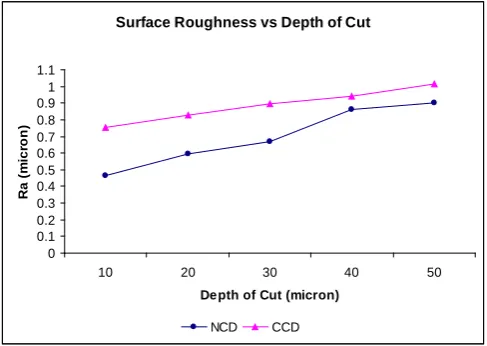
Fig. 5 Graph Surface Roughness as a Function of depth of cut
surface roughness as a function flow rate
0.5 0.54 0.58 0.62 0.66 0.7 0.74 0.78 0.82
0.04L/s 0.06L/s 0.08L/s
flow rate R a ( m icr o n ) CCD NCD
Fig.6 Graph surface Roughness as a Function of flow rate
The surface roughness obtained from the graph are calculated and the result Ra,Rt,Rz are summarized into a data table above. The graph Fig.5 shows the surface roughness as a function of grinding depth for both coolant devices in both cases, the surface roughness increase due to the increased of the grinding depth.
The surface roughness generated using the new coolant device is generally lower than the conventional coolant device. Ra,Rt,Rz for new coolant device generated time to time for difference depth of cut but for conventional coolant device the value are not distributed. This is because at time grinding process coolant not penetrates fully at the grinding zone and surface becomes not distributed at the same path. Therefore during measurement, the value is less correct.
so the coolant that supplied can easily go straight directly to the contact point but for the conventional device, there is a coolant splash to the surrounding areas.
Fig.6 and Table 6 shows a result of surface roughness as a function of flow rate using conventional nozzle device and new coolant device. In both cases, the surface roughness decrease due to the increase of the amount of coolant used in the grinding process. This is because when the amount of coolant becomes more, the more efficient the coolant functioned as working fluid. From the graph, at the flow rate 0.040L/s, the surface roughness generated using the conventional device better than new coolant device. However when the coolant flow rate increase, there is significant effect on the surface roughness generated using new coolant device. This is because the design of the new coolant device is such that the coolant is always contact and carry by the grinding wheel on the workpiece surface. The amount of coolant carried by the grinding wheel is depending on the porosity of the grinding wheel.
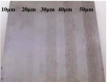
Fig.7 and Fig.8 show the workpiece that it was used in surface roughness test. There are grinding performance a new coolant device and conventional coolant device. The surfaces of the workepiece below were found to have scratching groves with certain ductility and also known as workpiece burn. Burn occurs when enough heat and energy is created by the grinding process to produce discoloration and blemishes which can be seen on the workpiece. As the surface temperature increases the microstructure of the material can change. As the microstructure changes, the hardness will vary. If the material is sensitive enough, the workpiece can even crack due to the residual stress or the localized thermal expansion from the grinding process.
Under the conventional coolant supply method, the coolant did not reach the ground surface and therefore the surface temperature rise, resulting burn as shown in Fig.8. However, the new coolant delivery method provides a coolant coating to the wheel become less discoloration and blemishes as shown in Fig.7.
Fig.7 Surface burning from 10µm to 50 µm depth of cut each slot. Table speed 0.12m/s. coolant supply 0.08L/s using NCD.
Fig. 8 Surface burning from 10µm to 50 µm depth of cut each slot. Table speed 0.12m/s, coolant supply 0.08L/s using CCD.
5. Conclusion
The effect of the boundary layer approaching the grinding zone has been shown to inhabit the coolant flow delivered under low flow rate.
To give the effectiveness of the grinding process, methods for optimum coolant flow application have been proposed. There is new coolant device (NCD).Performance this NCD compared with CCD to given improvement. For CCD, positions of nozzle also have been considered. Nozzle positioned horizontal and coolant delivered to the grinding wheel grain (porosity) became splash and spin off. This condition hazard for environment Position nozzle 15º from horizontal, coolant delivered through to entrance zone make a spin off reduce.
10µm 20µm 30µm 40µm 50µm
ISSN (Online) 2348 – 7968 www.ijiset.com Nozzle method (CCD) in this experiment was
found not enough fluid and not distributed to the wheel carried to grinding zone. NCD was shown to affect the volume of coolant passing beneath the grinding wheel. Bulk porosity of the grinding wheel important to carried coolant through to grinding zone. This was found during experiment of surface roughness test where using NCD better than CCD. It is depend on cutting depth where much depth of cut has virtually influence for surface roughness.
References
[1] S.Ebbrell,N.H.woolley,Y.D. S. Ebbrell, N.H. Woolley, Y.D.Tridimas, D.R. Allanson,W.B.Rowe, The effects of cutting fluid application methods on the grinding process. International Journal of Machine Tools & Manufacture 40 (2000) 209-223
[2] V.K. Gviniashvili, N.H. Woolley, W.B.Rowe. Useful coolant florate in grinding. International Journal of Machine Tools & Manufacture 44 (2004) 629-636 [3] K.Ramesh, S.H.Yeo, Z.W.Zhong, K.C.Sim, Coolant Shoe development for high efficiency grinding. Journal Of Materials Processing Technology 114 (2001) 240-245
[4] P.Hryniewicz, A.Z.Szery, S.Jahanmir, Coolant flow in surface grinding with non-porous wheels. International Journal of Mechanical Sciences 42 (2000) 2347-2367
[5] T. Nguyen, L.C.Zhang . The coolant penetration in grinding with segmented hweel – part 1: mechanism and comparison with conventional wheels. International Journal of Machine Tools & Manufacture 45 (2005) 1412-1420
[6] Aw Yong Sem(2003), Development of New Coolant Device And Study The Coolant Effect on Surface Grinding Machine. Mechanical Department Faculty of Engineering. UM.
[7] R.A. Irani1, R.J. Bauer*, A. Warkentin A review of cutting fluid application in the grinding process International Journal of Machine Tools & Manufacture xx (2005) 1–10