Study Of Effect The Soaking Time on Microstructure and
Hardness Of ( Steel Grid 60) Using Oil Type (Sheld)
Hamid Hussein Ali Nabil Kadhim Taieh [email protected] [email protected]
Ministry of higher education and scientific research
Middle technical university ,kut-technical institute, wasit, Iraq.
ABSTRACT
The aim of the study was to
determine the effect of thermal
treatment on the mechanical and physical properties of the metal low steel carbon type (steel grid 60) and access to the properties of the best and get rid of stresses within the metal
using a coolant (SHELD) is a good
specification in the cooling process where three pieces of distribution metal steel were carried out by three different types of heating (half an hour, an hour, an hour and a half), respectively, where the results were different for the microstructure of the
metal structure as well as hardness, when soaking time is up to one half-hour was a hardness (HRC 40.1) and at soaking time the amount of time an hour had hardness (HRC 40.9) The soaking time for a period of an hour and a half to be hardness (HRC 39.4), he must install up to one hour inside the oven gives the best of the crystal structure homogenized hand as well as through the hardness also results.
INTRODUCTION
diagram. Mechanical properties can be change by varying the relative properties of micro constituents. In
practice, change in mechanical
properties is achieved by a process known as heat treatment. This process consists of heating a metal or alloy
to a specific predetermined
temperature, holding at this
temperature for required time, and finally cooling from this temperature. All these operations are carried out in solid state. Sometime, it become necessary to repeat these operations to impart some characteristics. Therefore, heat treatment may be defined as
heating and cooling operation
(s)applied to metals and alloy in solid state so as to obtain the desired properties. Heat treatment of metals is an important operation in the final fabrication process of many engineer components. The object of this process is to make the metal better
suited, structure and physically, for
some specific application.[1]
THE THEORETICAL SIDE:
Thermal treatment of carbon steel:
the metal is heated to a certain temperature and then keep it at that rate for a period of time and then
cooling at a rate specified
cooling .otgery heat treatment to change the properties of the metal operations, which include: - process
1
- Increased hardness.
2
- Increased toughness.
3
- increase the susceptibility of metal
forming and operating processes.
4
- remove the internal stresses
resulting from operations.
5
- Remove the interactions forming
operations Cold
the steel and improves their good properties. Which include hardening steel heated to the point of adequate and sufficient heat to convert steel process (ferrite) to steel (Austenite) homogeneous in terms of chemical composition and temperature, after which the installation is for the purpose of the events heterogeneity in relation to the thermal distribution, as well as the crystal structure of the metal and then cools the metal quickly fit in with the amount of the required hardness. The temperature at which heated the steel and the time of treatment and the rate of cooling depends on several factors, including (chemical composition, portion size, mechanical properties required) The selection amid hardening is affected by the type of material to be configured and the final properties required for the product [2], and the most important characteristics that must be are available in the center of hardening are - :
A) High rate of cooling in shifts over the diffusivity, which is higher than the critical cooling rate.
B) Cooling and low for the extent of the transformations Martensitic rate, so as to avoid stresses and cracks
D) Heat capacity of high quality [ 3 [.
QUENCHING
Most of the oils used as quenchants are mineral oils. These are, in general, paraffin based and do not possess any fatty oils. Quenching in oils provides slower cooling rates as compared to those achieved by water quenching. The slow cooling rate
developed during oil quenching
reduces the possibility of introduction of hardening defects in the quenched
work piece. The temperature
Quenching oils are graded according to their viscosity values. Commonly used quenching oils have the viscosity values of about 100 SUS
( Saybolt Universal Seconds ) at 44 c.
For these oils, the duration of the first stage is found to be longer than the corresponding value achieved by water quenching .in addition to this, the cooling rate in second stage is also considerably lower, and the duration of this stage is shorter than that associated with water quenching. On account of all these factors, these oils are not considered well suited as quench ants where severe quenching is desired. However, they offer less distortion. For majority of application these oils are used at temperature varying from room temperature to 65 c. however, in certain cases, specially where slow cooling rates are required, oils are maintained in the temperature range 65 95 c.
For obtaining faster cooling rate, oils with viscosity values as low as 50 SUS at 40 c are employed. These oils are referred to as fast quenching oils. The duration of the fast stage is considerably less for these oils than for common oils. The initial cooling rate associated with these oils than approaching the value developed by water quenching.
Hot quenching oils generally possess viscosity values in the range 250-3000 SUS at 40 c. these include plain and inhibited mineral oils, which are generally used in the temperature range 100-150C. Use of these stable oils results in low distortion and cracking. These oils are
very well suited to quenching
intricately shaped objects.
Marquenching oils have viscosity values more than 2000 SUS at 40C. These oils are inhibited to provide
excellent oxidation and thermal
generally used at temperature higher than 150 C. These oils have specific advantage such as uniform cooling rate, minimum possible distortion and cracking.
The presence of water as an impurity in quenching oils is most
undesirable. It may lead to
development of non-uniform hardness distribution, distortion and crack, water can be removed by heating oils to 130 C for about 4 hours.[4] If a
slower cooling rate is desired, oil
quenches are often utilized. Various oils are available that have high flash points and different degrees of quenching effectiveness. Since the boiling points can be quite. high, the
transition to third-stage cooling
usually precedes the martensitic start temperature. The slower cooling
through the M,to-Mimartensitic
transformation leads to a milder temperature gradient within the piece,
reduced distortion, and reduced
likelihood of cracking. Heating the oil actually increases its cooling ability, since the reduced viscosity assists
bubble formation and removal.
Problems associated with oil
quenchants include water
contamination smoke fumes spill and disposal problems and fire hazard in addition quench oils tend to be somewhat expensive.[5]
DEFECTS IN STEEL THAT
MUST BE ADDRESSED
THERMAL TREATMENTS:
1- large-sized granules:
The properties of the bad steel is the size of the large-grained when Austenite shift as the granules start growing the higher the temperature and time of retention of cooling as the large particle size detrimental to the properties that less durability undergo durability tensile and shock and
relative elongation and less
susceptibility to cold forming.
Which makes the steel is equal in all steel parts, which gives different properties and weaknesses so that poses a threat.
3- internal stresses:
And be is due to non-thermal homogeneity discourage cooling as it happens in the welding may be
mechanically because of
manufacturing steel parts operations which abnormalities may occur.
4- cold deformation of crystalline
formation:
Dissuade cold forming (rolling,
pulling, roads) swell crystals in a certain direction and loses the metal
to become codified and N on the increase in the profile.
Before entering into the operations warming deal must study turned Austenite to perlite at temperatures
constant temperature and
continuously cooling because it is the basis for some of the heat-treated, such as hardening and auditing. The
shift Austenite at temperatures
constant temperature (the
Figure (1-1) Change in free energy with temperature Austenite and perlite Figure it can be concluded that the temperature of less than (Ar1) (when cooling) be free energy (for Austenite) higher than (for perlite) This means that perlite more stable than Austenite (at these temperatures) dissolve Austenite to a mixture of ( ferrite and cementite ), said that the shift Austenite to perlite process is a
process of crystallization are
spreading because the outputs of the shift vary in terms of the carbon concentration which greatly ferrite is
virtually free of carbon while
cementite be carbon concentration in it (6.67%) and in order to study the
process of turning Austenite to perlite
first, we will examine its
transformation in fixed degrees of heat and called on the curves that represent the shift with the passage of time and at constant temperatures curves (TTT) or curve-shaped (C). To create such curves heats small samples of steel to one degree temperature higher than (723 m) to become the internal structure of Austenite stable then cool samples quickly to certain temperatures, such as (650 500 400, 250) are kept at these grades with the study of
transformation Austenite shifting
means either volumetric or magnetic
means, where the relationship
0 2 4 6 8 10
0 20 40 60 80 100 F2 F3 F3 F1
723 CO
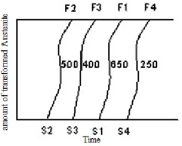
between the amount of paint Austenite unstable and time as shown in Figure (1-2).
Figure (1-2) the relationship between the amount of time and transformed Austenite
Figure(1-2) the relationship between the amount of time and transformed Austenite
Figure note that in each temperature there an initial period does not happen where a turning Austenite before passing (S4, S3, S2, S1) this period is called the period (wait or nursery), also note that after spending wait begins Austenite disintegrate and growing disintegration rate with the passage of time and then the rate begins a downward gradually after a specified period of time (F4, F3, F2, F1) complete disintegration process or stop .to draw a curve (TTT), we pass on the lengths of the time periods for the beginning of the shift (S4, S3, S2, S1) and the end switch (F4, F3, F2 F1) on the abscissa versus temperature on
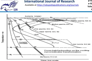
Figure (1-3) gave me T.T.T. For solid Aotktwedi
From this figure we note the following:
-1
First curve represents the beginning
of a turning Austenite
-2
Second curve represents the end of
the shift Austenite.
-3
Distance between these two curves
at any temperature represents the time required to complete the process of turning to P (+ Fe3C) (perlite).
-4
The area on the left of the first
curve represents the length of time to wait at a temperature.
5 - Length of the wait-and-transition
period represents over stability
Austenite The longer this period, this indicates that the Austenite more Astaqrara.an change in the stability of Austenite him (Figure 1-4) as the stability Austenite decline rapidly lower the temperature, reaching less than can be at about (500-550m) and then begin to increase again. [6[
Experimental procedure
Illustration of a section of the sample (steel grade 60)
After it is put the metal to be cut heated to a 930 temperature c degrees
inside the oven and increase oven temperature to the desired degree, and after the arrival of the temperature to 930 c is proving the time period for the iron pieces so that the installation of the first piece (half-hour) and a second ( a full hour) and the third (and a half hours) and after the installation is cooled in central tempering (oil type (shield)) good cooling specifications of the coin, as in the table below:
TYPICAL PHYSICAL CHARACTERISTICS
CHARACTERISTICS 20W-50
Kinematic Viscosity (IP 71)@ 40°C mm2/s@ 100°C mm2/s 15719.0
Viscosity Index (IP 226) 137
Density @ 15 kg/m3 (IP 365) 888
Flash Point °C (PMCC) (IP 34) 215
Pour Point °C (IP 15) –27
[ 7 ]
Table(1) specification of shield oil
We then process (poly Schenk) and then Manifesting using the solution
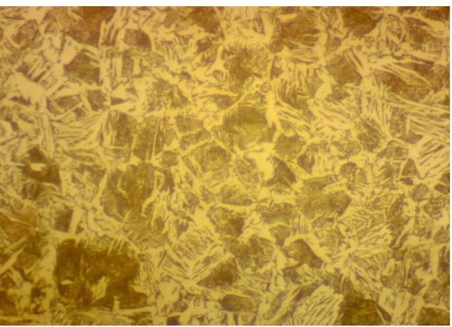
Figure (2) the image of the eye after taking them out of the oven and expose it to the widget temperature (930 c) a time (half an hour)
And Figure (3) shows the image of the sample after taking them out of the oven
And Figure (4) shows the image of the sample after taking them out of the oven temperature (930 c) a time (hour and a half)
The figure shows the effect of heating time on the microstructure of the steel structural type 60 where A
represents the heating time at 30 minutes and B represent the heating
تيارفلااا
(
ضيبلاا نوللا
) white (
color ) ferrite austenite
( black
color ) austenite
( black
color )
( white
color ) ferrite
B
A
Perlite Segments
time of 60 minutes and C and heating at 90 minutes
After the display process of the structure of the microstructure was examined hardness of each piece of metal steel was the hardness of the piece installed time-half an hour (H.R.C 40.1) and pieces installed period of time clock (H.R.C 40.9) and pieces installed a period of time and a half hours (H.R.C 39.4).
CONCLUSION
1
- Figure 1 note an increase in the particle size of the Austenite.
2
- When steel heated to a temperature of 900 C leads to a shift Lafraat and Alberleight to Austenite.
3
- when increasing the heating time increases Austenite growth and rapid cooling when the huge structures consisting of Austenite.
4
- When you increase the heating time to 90 minutes are three phases which Austenite and Alberleight and ferrite.
5- hardness of the metal is heated and installer period of time (one hour) better than the installation of a half-hour, as well as for an hour and a half
REFERENCES
1)T.V.
Rajan
and
C.P.
Sharama,heat treatment principle
and techniques,2008.
(
2 R .A . Higging , Engineering"
Metallurgy "part 1&2.the English University press Ltd ;London.
(
3 M .S . Burton "Applied
Metallurgy for Engineers "McGraw Hill B00k company , inc .New York.
4)
Ronald
a.kohser2008‘
materials and
process in manufacturing ‘ tenth
edition.
5) S.L. Semiatin and D.E. Stutz,
Induction Heat Treatment of
Steel, ASM International, Metals
Park,
OH, 1986.
(
6 Carl A . Keuser "Basic Engineering Metallurgy", Prentice –
Hall, Englewood Cliffs , U .S.A