ISSN: 2319-8753
I
nternational
J
ournal of
I
nnovative
R
esearch in
S
cience,
E
ngineering and
T
echnology
(An ISO 3297: 2007 Certified Organization)
Vol. 2, Issue 10, October 2013
Copyright to IJIRSET www.ijirset.com 5131
STUDY OF BOILING CHARACTERISTICS OF
R744/R1270 IN A SMOOTH HORIZONTAL
TUBE
A.Ramanan
1*, P.Senthilkumar
2, V.Natarajan
3, Amala Justus Selvam
4Research Scholar, Dept. of Mechanical Engineering, Sathyabama University, Chennai, India1 Professor, Dept. of Mechanical Engineering, KSR College of Engineering, Tiruchengode, India2
Professor, Dept. of Mechanical Engineering, Jeppiar Engineering college, Chennai, India3
Professor, Dept. of Automobile Engineering, Vel Tech Dr RR & Dr SR Technical University,Chennai 4
*
Corresponding author
Abstract: This paper presents the boiling heat transfer characteristics of the refrigerant mixture of R744/R1270 flowing through the horizontal smooth tube. The refrigerant mixture is studied in different mass and heat flux conditions. Experimental results on the heat transfer coefficient, inner wall temperature, exergy and Nusslet number of mass flux from 40 to 80 kg/ m2 s and 15 to 24 Kw/m2s in a horizontal smooth tube of 4 mm inner diameter are provided.
Keywords: heat flux, mass flux, refrigerant mixture
I.
INTRODUCTIONConventional refrigerants, such as the CFCs and their alternatives the HFCs, have potential environmental problems, so their use is being restricted. Natural substances like water, hydrocarbons and CO2 are all in consideration for
replacements as working fluids.CO2 is non-flammable and nontoxic with a zero ozone depletion potential (ODP), and a
global warming potential (GWP) that is very small compared with other conventional refrigerants such as R134a; therefore, CO2 is a promising refrigerant for environmental, economical and safety reasons .
II. EXPERIMENTAL APPARATUS AND PROCEDURE
A. Experimental apparatus
ISSN: 2319-8753
I
nternational
J
ournal of
I
nnovative
R
esearch in
S
cience,
E
ngineering and
T
echnology
(An ISO 3297: 2007 Certified Organization)
Vol. 2, Issue 10, October 2013
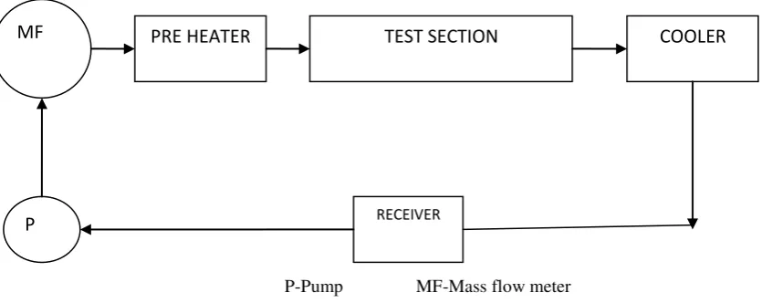
Copyright to IJIRSET www.ijirset.com 5132 P-Pump MF-Mass flow meter
Figure 1 Experimental Set Up
B Instrumentation
Instruments used in the experimentation while doing the experiment is listed in the table 1 with their range and accuracy. The instruments where calibrated as per the standard procedure before they were utilised.
Table1 instruments and its accuracy
Sl. No Instrument Range Accuracy
1 PT100 type temperature sensors -50 °C to 100 °C ±0.5
2 Mass Flow Meter 0-400L/ min. ±1.0
3 Pressure gauge 0-500Kg/cm2 ±1.2
C.Data reduction
The thermo physical properties are calculated based on the measured temperature and pressure. The local heat transfer coefficient at each thermocouple is calculated based on the following equation
h = q / (Tw -Tsat) Where, q- heat flux,
Tw is the inner wall surface temperature
Tsat is the saturated temperature of the refrigerant deduced from the fluid pressure. The variations of the refrigerant thermo-physical properties in the test section were calculated with REFPROP 8.0.
D.Uncertainty analysis
An estimate of the internal uncertainty (Nakra and Chaudhary1991), has been carried out and given in the table 2.
MF
P
PRE HEATER
TEST SECTION
COOLER
ISSN: 2319-8753
I
nternational
J
ournal of
I
nnovative
R
esearch in
S
cience,
E
ngineering and
T
echnology
(An ISO 3297: 2007 Certified Organization)
Vol. 2, Issue 10, October 2013
Copyright to IJIRSET www.ijirset.com 5133 Table 2 Percentage of uncertainty of different parameters
Sl. No. Parameter Percentage of uncertainty
R744/R1270 (as75/25 by wt) 1
Test section temperature (°K) ±2.13
2
Test section inlet pressure (bar) ±2.36
3 Test section outlet Pressure(bar) ±5.91
4 Heat transfer coefficient ±3.58
5 Exergy ±2.96
6 Test section inner wall temperature (°K) ±3.39
7 Nusselt number ±4.16
III. RESULTS AND DISCUSSIONS
The investigation on flow boiling heat transfer coefficient, variation on inner wall temperature , Nusselt number and exergy with respect to mass and heat flux of the refrigerant mixture R744/R1270(75/25 mixture) is presented in the following sections.
A. Behaviour of R744/R1270 (72/25) mixture at different mass flux conditions
The variation of heat transfer co efficient, inner wall temperature, exergy and Nusslet number on the quality of refrigerant mixture flowing through the horizontal tube at different mass flux conditions is shown in fig. 2-5.
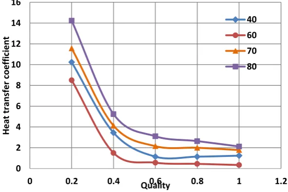
Fig.2. Variation of heat transfer coefficient vs quality at different mass flux
0 2 4 6 8 10 12 14 16
0 0.2 0.4 0.6 0.8 1 1.2
H
e
a
t
tr
a
n
sf
e
r
co
e
ff
ic
ie
n
t
Quality
40
60
70
ISSN: 2319-8753
I
nternational
J
ournal of
I
nnovative
R
esearch in
S
cience,
E
ngineering and
T
echnology
(An ISO 3297: 2007 Certified Organization)
Vol. 2, Issue 10, October 2013
Copyright to IJIRSET www.ijirset.com 5134
The heat transfer coefficient decreases drastically up to first part then gradually along the section. With the increase of mass flux heat transfer coefficient increases but for the mass flux of 60 Kg/m2s it decreases. The heat transfer coefficient is maximum for the mass flux of 80 Kg/m2s and is low for 60 Kg/m2s.
Fig.3. Variation of inner wall temperature vs quality at different mass flux
The inner wall temperature of the test section steadily increases for all mass fluxes and approaches same pattern .The maximum inner wall temperature is for 60 Kg/m2s and minimum is for 40 Kg/m2s. The inner wall temperature at higher mass fluxes decreased and lies between the mass fluxes 40 Kg/m2s and 60 Kg/m2s as in the figure 3.
Fig.4. Variation of exergy vs quality at different mass flux
285 290 295 300 305 310
0 0.2 0.4 0.6 0.8 1 1.2
In
n
e
r
w
a
ll
t
e
m
p
e
ra
tu
re
Quality
40
60
70
80
0 2 4 6 8 10 12 14 16
0 0.2 0.4 0.6 0.8 1 1.2
E
x
e
rg
y
Quality
40
60
70
ISSN: 2319-8753
I
nternational
J
ournal of
I
nnovative
R
esearch in
S
cience,
E
ngineering and
T
echnology
(An ISO 3297: 2007 Certified Organization)
Vol. 2, Issue 10, October 2013
Copyright to IJIRSET www.ijirset.com 5135 The exergy of the mixture decreases along test section at all the mass fluxes. The maximum exergy is for 40 Kg/m2s and minimum exergy is for 70 Kg/m2s. The exergy of the mixture decreases faster rate in the first part and then gradually for 60 Kg/m2s and 80 Kg/m2s varies in similar way. But for the mass fluxes 40 Kg/m2s and 70 Kg/m2s the variation of exergy uniform.
Fig.5. Variation of Nusselt number vs quality at different mass flux
The variation of Nusslet number of the mixture on the quality along the test section is shown in fig5. The Nusslet number of the mixture decreases towards the end of tube. Higher value Nusslet number is evident at a mass flux of 40 Kg/m2s and low value is for the mass flux at 70 Kg/m2s.The value of Nusslet number for the other mass fluxes lies in between these two.
B. Behavior of R744/R1270 (75/25) mixture at different heat flux conditions
The variation of heat transfer co efficient, inner wall temperature, exergy and Nusslet number on the quality of refrigerant mixture flowing through the horizontal tube at different heat flux conditions is shown in fig. 6-9.
Fig.6. Variation of heat transfer coefficient vs quality at different heat flux
0 2 4 6 8 10 12 14
0 0.2 0.4 0.6 0.8 1 1.2
N
u
Quality
40
60
70
80
0 2 4 6 8 10 12
0 0.2 0.4 0.6 0.8 1 1.2
H
e
a
t
tr
a
n
sf
e
r
co
e
ff
ic
ie
n
t
Quality 15
18 21
ISSN: 2319-8753
I
nternational
J
ournal of
I
nnovative
R
esearch in
S
cience,
E
ngineering and
T
echnology
(An ISO 3297: 2007 Certified Organization)
Vol. 2, Issue 10, October 2013
Copyright to IJIRSET www.ijirset.com 5136
The heat transfer coefficient of the mixture is increases as the heat flux increases with an exception to higher heat flux of 24 Kw/m2s. The heat transfer co efficient of the mixture is maximum for the heat flux of 21 Kw/m2s and it is low for the heat flux of 15 Kw/m2s as it is evident from fig 6.The variation of heat transfer coefficient is gradual increase for 15 Kw/m2s, steady increase for 21 Kw/m2s and for the other two heat flux conditions it increases with fluctuations.
Fig.7. Variation of inner wall temperature vs quality at different heat flux
Inner wall temperature of the test section increases steadily from the beginning along the tube section for all the heat flux conditions. Variation of inner wall temperature of the test section follows similar pattern with an exception for the heat flux of 15 Kw/m2s as in fig 7.The higher inner wall temperature occurs for the low heat flux of 15 Kw/m2s and low value is for 24 Kw/m2s.
Fig.8. Variation of exergy vs quality at different heat flux
The exergy initially has high value for the mixture but decreases along the test section as in fig 8. The value is highest at the heat flux of 18 Kw/m2s as compared with other heat fluxes and is low for the heat flux of 21
265 270 275 280 285 290 295 300
0 0.2 0.4 0.6 0.8 1 1.2
In
n
e
r
w
a
ll
t
e
m
p
e
ra
tu
re
Quality
15
18
21
24
0 5 10 15 20 25 30 35 40
0 0.2 0.4 0.6 0.8 1 1.2
E
x
e
rg
y
Quality 15
18
21
ISSN: 2319-8753
I
nternational
J
ournal of
I
nnovative
R
esearch in
S
cience,
E
ngineering and
T
echnology
(An ISO 3297: 2007 Certified Organization)
Vol. 2, Issue 10, October 2013
Copyright to IJIRSET www.ijirset.com 5137 Kw/m2s.The variation of the exergy almost follows similar pattern at all heat flux condition. The exergy value for high heat flux 24 Kw/m2s occurs in between the low heat fluxes.
Fig.9. Variation of Nusselt number vs quality at different heat flux
The Nusselt number increases for all heat flux conditions along the test section as in fig 9. The value is highest at the heat flux of 15 Kw/m2s as compared with other heat fluxes and is low for the heat flux of 24 Kw/m2s.The variation of the Nussle number follows similar pattern for 15 and 21 Kw/m2s heat flux condition, for 18 Kw/m2s the Nusselt number varies with deviation in the middle part and for 24 Kw/m2s it decreases at the end portion.
IV. CONCLUSIONS
Experimental results for the flow boiling of R744/R1270 as 75/25 mixture combination in a horizontal tube under variations in the mass flux and heat flux were presented. The behaviours of the local heat transfer coefficient, inner wall temperature, Nusselt number and exergy were reported.
In the low heat flux conditions, it was possible to observe a significant influence of heat flux on the heat transfer coefficient. In the high heat flux conditions, this influence tended to disappear and the coefficient decreased;
The influence of mass velocity on the refrigerant mixture, it is revealed that, the heat transfer coefficient decreases drastically up to first part then gradually along the section. The inner wall temperature of the test section steadily increases for all mass fluxes and approaches same pattern. The exergy of the mixture decreases along test section at all the mass fluxes. The Nusslet number of the mixture decreases towards the end of tube.
REFERENCES
[1].Jin Min Cho,Yong Jin Kim and Min Soo Kim , Experimental studies on the characteristics of evaporative heat transfer and pressure drop of CO2 /PROPANE mixtures in horizontal and vertical smooth and microfin tubes,IJR,VOL33,2010,PP170-179.
[2]. Jin Min Cho, Yong Jin Kim and Min Soo Kim, Experimental studies on the evaporative heat transfer and pressure drop of CO2 and CO2 /propane mixtures flowing upward in smooth and micro-fin tubes with outer diameter of 5mm for an inclination angle 45 0,IJR,VOL33,2010,PP922-931. [3].Jin Min Cho and Min Soo Kim , Experimental studies on the evaporative heat transfer and pressure drop of CO2 smooth and microfin tubes of diameters 5 and 9.52 mm,IJR,VOL30,2007,PP986-994.
[4]. Jose Maria Saiz Jabardo Enio Pedone Bandarra Filho , Convective boiling of halocarbon refrigerants flowing in a horizontal copper tube - an experimental study, Experimental Thermal and Fluid Science VOL23,2000,PP93-104.
[5]. Enio P. Bandarra Filhoa,b, Lixin Chengb, John R. Thomeb, Flow boiling characteristics and flow pattern visualization of refrigerant/lubricant oil mixtures, International journal of refrigeration ,VOL32,2009,PP185–202.
[6]. X. Zou a,b, M.Q. Gong a,G.F. Chen a,b, Z.H. Sun a, Y. Zhang a, J.F. Wua, Experimental study on saturated flow boiling heat transfer of R170/R290 mixtures in a horizontal tube, International journal of refrigeration ,VOL33,2010,PP371–380.
0 1 2 3 4 5 6
0 0.2 0.4 0.6 0.8 1 1.2
N
u
Quality 15
18
21