ISSN: 2319-8753
I
nternational
J
ournal of
I
nnovative
R
esearch in
S
cience,
E
ngineering and
T
echnology
(An ISO 3297: 2007 Certified Organization)
Vol. 3, Issue 8, August 2014
Synthesis and Characterization of Al-SiC
Functionally Graded Material Composites
Using Powder Metallurgy Techniques
R Kumar
1, Dr C N Chandrappa
2Research Scholar, Assistant Professor, Department of Mechanical Engineering, MSRIT, Bangalore, India 1 Professor, Department of Automobile Engineering, Acharya Institute of Technology, Bangalore, India2
ABSTRACT: An overview of the processing, mechanical analysis and performance of Al-SiC functionally graded materials is studied .Established powder metallurgy technique is used in the processing phase. The effect of SiC addition on the density of Al, densification parameters of Al sintered functionally graded materials are studied.
KEYWORDS: Functionally Graded Materials; Powder metallurgy; Sintering;
I. INTRODUCTION
In materials science functionally graded materials (FGM) may be characterized by the variation in composition and structure gradually over volume, resulting in corresponding changes in the properties of the material. The materials can be designed for specific function and applications. For example a combination of materials used would serve the purpose of a thermal barrier capable of withstanding a surface temperature of 2000K and a temperature gradient of 1000K across a 10mm section. The gradation in properties is brought about by varying the microstructure from one material to another with a specific gradient. The manufacturing process of a FGM can usually be divided in building the spatially inhomogeneous structure (“gradation”) and transformation of this structure into a bulk material (“consolidation”).Gradation processes can be classified into constitutive, homogenizing and segregating processes. Constitutive processes are based on a stepwise build-up of the graded structure from precursor materials or powders. In homogenizing processes a sharp interface between two materials is converted into a gradient by material transport. Segregating processes start with a macroscopically homogeneous material which is converted into a graded material by material transport caused by an external field (for example a gravitational or electric field). Homogenizing and segregating processes produce continuous gradients, but have limitations concerning the types of gradients which can be produced. Usually drying and sintering or solidification follow the gradation step. Since the sintering behavior is influenced by porosity, particle size and shape and composition of the powder mixture, these problems must be handled for each materials combination and type of gradient individually referring to the existing knowledge about the sintering mechanisms.
II. MATERIALS AND METHODS
The two basic methods in the preparation of FGMs are
i) Powder Metallurgy ii) Liquid Metallurgy
By the powder metallurgy route the following types of gradients can be processed:
Porosity and pore-size gradients
ISSN: 2319-8753
I
nternational
J
ournal of
I
nnovative
R
esearch in
S
cience,
E
ngineering and
T
echnology
(An ISO 3297: 2007 Certified Organization)
Vol. 3, Issue 8, August 2014
Gradients of the volume content of phases and grain size gradients in two or multiphase materials.
In the present work, processing and fabrication of Al-SiC functionally graded materials have been discussed. The effect of SiC addition on the density of Al 6061 alloy (0-20%) and densification parameters of Al 6061 sintered Functionally Graded Materials at high temperatures have been observed and studied. A comparative chart of hardness(BHN) for different percentages of Al 6061 FGM at different SiC percentages and fracture structure at different percentages of SiC have been studied and the data have been calibrated.
III. EXPERIMENTAL DETAILS
Samples were prepared by varying the weight percentages of Aluminium and SiC and by keeping the weight percentage of Mg at 2% which acts like a binder.
Sample 1: 90%-2%-8%(Al-Mg-SiC) Weight of Al-89.285g
Weight of SiC- 9.435g Weight of Mg-1.278g
Sample 2: 95%-2%-3%(Al-Mg-SiC) Weight of Al- 95.137g
Weight of SiC-3.571g Weight of Mg-1.29g
Sample 3: 80%-2%-18%(Al-Mg-SiC) Weight of Al -77.905g
Weight of SiC-20.839g Weight of Mg-1.255g
Sample 4: 60%-2%-38%(Al-Mg-SiC) Weight of Al-56.355g
Weight of SiC-42.433g Weight of Mg- 1.01g
Each sample is split into 50g each and put into small boxes and tied with metal twine to increase the friction between the box and the surface of contact so that the box is rotating at all times. Put the two prepared boxes inside a grinder with a wooden stick as an obstruction which will help the boxes tumble continuously after every rotation. The wooden stick is placed on the extreme outer surface so that the box collides with the wooden construction and pushes the two boxes towards the centre of the grinder, due to the centripetal force acting on the two boxes it is pushed to the outer surface before it reaches the wooden obstruction again. This causes the boxes to rotate continuously and this process is done for 2 hours for each sample .the grinder speed is 150 rotations per minute. This process helps the powders to mix properly and the distribution of the reinforcement is almost equal in the metal matrix.
This powder is filled inside the mechanical die layer wise and this combination is mentioned below in the Table 2.1
Sl.No Combination (Al-SiC-Mg)
Weight of Al (g) Weight of SiC (g)
Weight of Mg (g)
1. 90%-8%-2% 89.285 9.435 1.278
2. 95%-3%-2% 95.137 3.571 1.29
3. 80%-18%-2% 77.905 20.839 1.255
ISSN: 2319-8753
I
nternational
J
ournal of
I
nnovative
R
esearch in
S
cience,
E
ngineering and
T
echnology
(An ISO 3297: 2007 Certified Organization)
Vol. 3, Issue 8, August 2014
The percentages being that of aluminium 6061 and the rest of it being silicon carbide are added layer by layer (functionally graded) in each sample and then compacted in the same order.
IV. SAMPLE PREPARATION
Two, three and four layered FGM samples were prepared for Al/SiC system using very small amount of Mg as a binder. Sample designation and composition are shown below.
1. 100%-90%-80% 2. 90%-80%-60% 3. 100%-95%-90%-80% 4. 95%-90%-80%-60%
In the first sample, the first layer consists of 3.5g of pure Al, the second layer consists of 3.5g mixture of 90% Al & 10% SiC and similarly the third layer consists of 80% Al & 20% SiC. The total weight of the sample is 10.5g. Four samples were prepared for each composition to ensure the uniform precision of the values of the different samples.
V .COMPACTION AND SINTERING
Once the samples are prepared, they are compacted. A die is placed on the universal testing machine and the powder is compacted at 370kN – 400kN for 5 minutes of constant loading.
The samples are ejected out and placed in a muffle furnace (non-inert) for sintering process. The samples are heated to 600 degree Celsius and maintained at that temperature for 3 hours and cooled in the furnace itself. The samples are removed and ground over a grinding wheel and then scraped over different particle size abrasive paper till mirror finish obtained for pure aluminium. The samples are then polished over a velvet polishing wheel with alumina powder for obtaining proper smooth surface. The samples are kept for microstructure analysis and then the samples are etched for obtaining proper grain structure under the microscope.
VI. TESTING AND CHARACTERIZATION MICROSTRUCTURAL STUDY
The microstructural characterization of the metallographic polished samples of Al-SiC was carried out using the DE winter scanning electron microscope with a resolution of 100X. The polished samples were dipped in nitric acid for 30 seconds for etching of the samples and it was then dried and taken away for microstructural study.
DENSITY STUDY
The sintered density determination is carried is carried out following the procedure of ISO standard 2738. This is valid for both dry parts and parts that have been impregnated with oil. The density may be calculated by the oil impregnation method, the formula being:
g cm
Where, A is the mass of un-impregnated part in air, B is the mass of the part after impregnation with the oil and C is the mass of impregnated part in water.
POROSITY STUDY
ISSN: 2319-8753
I
nternational
J
ournal of
I
nnovative
R
esearch in
S
cience,
E
ngineering and
T
echnology
(An ISO 3297: 2007 Certified Organization)
Vol. 3, Issue 8, August 2014
Where = density of sintered specimen (kg/m^3), density of water (kg/m^3)
Ma= weight of sample in air (kg), mw= weight of sample in water (kg). The density was also measured by measuring the weight and volume of the specimens. The volume was determined by measuring the accurate dimensions of the specimen. The porosity was determined by using the formula:
Where E= porosity (%), theoretical density (kg/m^3).
VII. RESULTS AND DISCUSSION
MICROSTRUCTURE AND PHASE EVOLUTION OF SINTERED COMPOSITES
Fig7.1 shows the optical micrographs of Al-SiC sintered composites with varying amount of SiC reinforcement. Microstructure with well-defined grains and lesser amount of porosity mostly at inter granular regions can be seen for unreinforced alloy (Fig.7.1(a) ).Composites having SiC up to 10 vol. %, (Fig 7.1(b) ) shows uniform distribution of reinforcing phase in between the Al grains. Increasing SiC beyond 10 vol. % causes the clustering of carbide phase at grain boundaries which further restricts the inter particle contacts and densification. It is hypothesized that small amount of SiC addition restricts the microstructural coarsening of Al matrix during SLPS. Consequently, this entails that the pores do remain inter granularly dispersed and hence can be readily removed through grain boundary diffusion. At lower volume fractions of reinforcement, liquid phase can bypass the dispersion and fills the voids around it. At higher vol. % (beyond 10 vol. %), the phase cannot pass through the SiC cluster and consequently the densification does not occur by aluminum.
(a) (b)
(c ) (d)
International Journal of Innovative Research in
Science, Engineering and Technology
(An ISO 3297: 2007 Certified Organization)
Vol. 3, Issue 8, August 2014
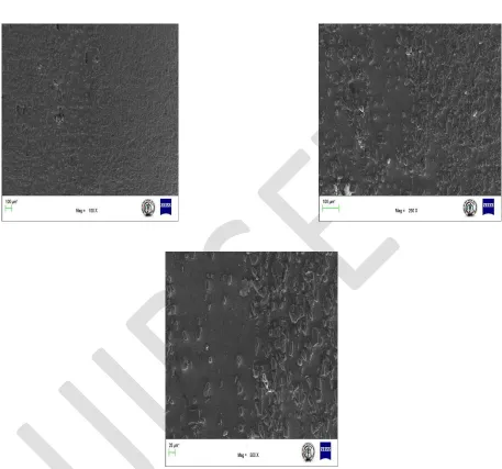
The optical microscope images shows the distribution of SiC particles in the sample with varying percentages. Fig (7.2) shows the distribution and the division between the different layers of the FGM. Fig 7.2shows the distribution of SiC particles in the sample with varying percentages obtained by using a Scanning Electron Microscope.
International Journal of Innovative Research in
Science, Engineering and Technology
(An ISO 3297: 2007 Certified Organization)
Vol. 3, Issue 8, August 2014
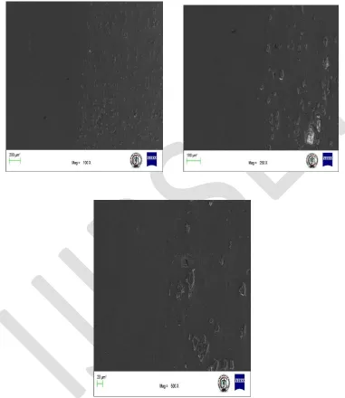
Fig 7.4 (a), (b) and (c) is obtained using a Scanning Electron Microscope showing the transition from 80% aluminium layer to 60% aluminium layer using magnification of 100X, 250X and 500X respectively.
DENSIFICATION BEHAVIOR OF SINTERED COMPOSITES
International Journal of Innovative Research in
Science, Engineering and Technology
(An ISO 3297: 2007 Certified Organization)
Vol. 3, Issue 8, August 2014
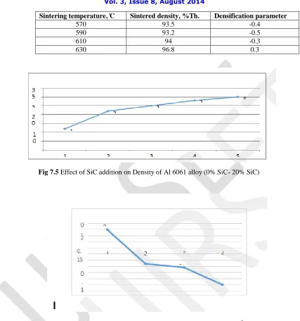
Sintering temperature, ̊C Sintered density, %Th. Densification parameter
570 93.5 -0.4
590 93.2 -0.5
610 94 -0.3
630 96.8 0.3
Fig 7.5 Effect of SiC addition on Density of Al 6061 alloy (0% SiC- 20% SiC)
Fig 7.6 Densification Parameter of Al 6061 sintered FGM’s at 630oC for 3hrs
International Journal of Innovative Research in
Science, Engineering and Technology
(An ISO 3297: 2007 Certified Organization)
Vol. 3, Issue 8, August 2014
The effect of SiC content on sintered density and densification parameter of 6061 compact pressed at 400Mpa and sintered at 630 ̊C is shown in Fig. 7.5. The variation of densification parameter is shown in Fig. 7.6. It can be observed that sintered density of composite marginally decreases up to 10 vol % of SiC, followed by significant decrease at higher fractions (beyond 10 vol %). The densification parameter follows similar trend as sintered density. The positive densification parameter indicates shrinkage and negative indicates swelling during sintering. The extent of swelling increases with increasing SiC volume fraction. The adverse influence of SiC additive on densification at higher volume fractions is attributed to clustering of SiC particles and poor wettability of SiC surface by melt during sintering. This behavior is attributed to associated stress field that activates the sintering in Al composites. It can be summed up that addition of SiC particles should not adversely affect the densification of super solidus phase sintered Al 6061-SiC composites up to the lower volume fractions (10%)
VIII. CONCLUSION
The effect of SiC content on densification, microstructure, phase evolution and properties of super solidus liquid phase sintered Al 6061-SiC composites were studied. Higher volume of fractions of SiC (beyond 10 wt. %) caused clustering of carbide phase at grain boundaries which restricts the inter particle contacts further inhibiting densification. The hardness of Al6061-Sic composites increased with increasing wt. percentage of SiC due to dispersion hardening effect.
(a) The results of study suggest that with increase in composition of SiC, an increase in hardness, impact strength and normalized displacement have been observed.
(b) The best result have been obtained at 25% weight of 320 grit size SiC particles. Maximum hardness=44.8 BHN and maximum fracture strength=37 N-m.
(c) The Functionally graded materials generally exhibited superior fracture resistance to conventional composites. The FGM’s exhibited some load carrying capacity after the initial crack propagation stage. Replacing the discreet interfaces in a multilayer FGM with the continuous SiC distributed resulted in a slightly improved fracture toughness.
REFERENCES
[1] E. Muller, C. Drasar, J. Schilz, W.A. Kaysser, Mater. Sci. Eng. A 362 (2003) 17–39.
[2] U. Schulz, M. Peters, F.W. Bach, G. Tegeder, Mater. Sci. Eng. A 362 (2003) 61–80.
[3] A.H. Wu, W.B. Cao, C.C. Ge, J.F. Li, A. Kawasaki, Mater. Chem. Phys. 91 (2005) 45–50. [4] R. Hill, J. Mech. Phys. Solids 13 (1965) 213–222.
[5]T. Mori, K. Tanaka, Acta Mater. 21 (1973) 571–574. [6] K. Wakashima, H. Tsukamoto, Mater. Sci.