Strats
S
ELECTRONIC KEY TELEPHONE SYSTEM
-TOSHIBA SYSTEM PRACTICES
ELECTRONIC KEY TELEPHONE SYSTEM
TOSHIBA PUBLICATIONS SECTION 100-003-000 .
JULY 1984
e..
Strata” S
(AKA: HARRIS LANIER SERIES III)
E L E C T R O N I C K E Y T E L E P H O N E S Y S T E M
INSTALLATION AND MAINTENANCE MANUAL
.
TABLE OF CONTENTS
FCC REGULATIONS
SECTION 100-003-000
GENERAL DESCRIPTION
SECTION 100-003-l 00
INSTALLATION INSTRUCTIONS
SECTION 100-003-200
POWER SUPPLY INSTALLATION INSTRUCTIONS
SECTION 100-003-250
PROGRAMMING PROCEDURES
SECTION 100-003-300
OPERATING PROCEDURES
SECTION 100-003-400
TOSHIBA SYSTEM PRACTICES
ELECTRONIC KEY TELEPHONE SYSTEM GENERAL DESCRIPTIONSECTION 100-003-l 00
S t r a t a
S@
GENERAL DESCRIPTION
,.--P
TOSHIBA SYSTEM PRACTICES
ELECTRONIC KEY TELEPHONE SYSTEM _..
S t r a t a
S
GENERAL DESCRIPTION
TABLE
of CONTENTS
GENERAL OESCRlPTlON SECTION 100-003-l 00
JULY 1994
PARAGRAPH SUBJECT PAGE
01
0 2 0 2 . 0 0 0 2 . 1 0
0 3 0 4
0 5 0 6 0 6 . 0 0 0 6 . 1 0 0 6 . 2 0 0 6 . 3 0 0 6 . 4 0 0 7 0 7 . 0 0 0 7 . 1 0 0 7 . 2 0
TABLE of CONTENTS . . . . i
ILLUSTRATION LIST . . . . i
G E N E R A L 1 PHYSICALDESCRIPTI’ONS’::::::::::::::::::::::::: 1 Key Service Unit . . . . 1
Electronic Key Telephone TABLE A-SUMMARY OF ELEC;R;C~;CHARACTERlST;CS - : : : : : : : : : : 24 . ELECTRICAL CHARACTERISTICS . . . . 5
FEATURES and SERVICES 5 T A B L E B - S T A N D A R D F E A T U R E S ’ : : : : : : : : : : : : : : : : : : : : : : 5 TABLE C-OPTIONAL FEATURES . . . . 5
SYSTEM OPERATION SYSTEM CONFIGURATION ’ : : : : : : : : : : : : : : : : : : : : : : : : : 68 Key Service Unit . . . . 8
Power Supply Assembly . . . . 8
Station Equipment . . . . 9
Installation . . . . 10 . . .
Maintenance . . . . 10
FEATURESandOPERATlON . . . . :::::::: 1 0 General . . . . 10
Standard Features . . . . 10
OptionalFeatures . . . . :::::::: 1 2 NUMBER TITLE PAGE 1 2 3 4 5 6 7 8 3 1 0 1 1 12 13 14 15 MKSU (Dimensions) . . . . 1
MKSU Cabinet . . . . 1
MKSU (Internal) . . . . 1
1 O-key “S” Electronic Key Telephone (EKT) . . . . 2
1 O-key Speakerphone EKT . . . . 3
Busy Lamp Field (BLF) EKT . . . . 3
20-key Executive EKT SystemDiagram . . . . :::::::: 63 Functional Block Diagram . . . . 7
MKSU (Internal) . . . . 8
1 O-key “S” EKT . . . . 3
Key Layout . . . . 3
lo-key EKT . . . . 9 BLF EKT
-P
w..
Ot GENERAL-
01 .OO Summary Description
01.01
Strata
S is an electronic key tele-phone system with many standard features utiliz-
ing stored program control, custom LSI circuitry,
solid-state space division switching, and reduced
station cabling. Served by a key service unit
(MKSU) housed in a single cabinet, the system has
a capacity of three central office/PBX lines, one
intercom line, and eight station lines.
01.02 Strata S utilizes specially designed
electronic key telephones (EKTs). Each EKT is con-
nected to the system via industry-standard 2-pair
cabling, and is equipped with a push-button dial
pad. Solid-state electronics within the MKSU
translate signals from the station dial pad into
either DTMF or rotary dial signals, as required by
the central off ice.
01.03 Strata S is electrically compatible
with the public telephone network and is also
designed to function in a “behind PBX” envi-
ronment.
01.04 Maintenance procedures are based on
quickly locating and replacing defective sub-assem-
blies, keeping service disruption to a minimum.
02 PHYSICAL DESCRIPTIONS
02.00 Key Service Unit
02.01 Designed for wall mounting, the
Strata S MKSU is housed in a single plastic
cabinet (Figure 1) with the following dimensions:
GENERAL DESCRIPTION
SECTION 100-003-100 JULY 1984
Height: 16.5 inches (420 mm)
Width: 12.0 inches (306 mm)
Depth: 2.6 inches (67 mm)
Weight: 6.2 Ibs. (2.8 kg) .
02.02 The cabinet consists of a base, cover. and
side covers (Figure 2)
I
FIGURE 2-MKSU
CABINET
02.03 The MKSU is factory-equipped with two
PCBs (MMAU and ACOU). The dimensions of
these PCBs are:
MMAU: 15.4 x 9.5 inches (390 x 241 mm)
ACOU: 9.4 x 6.3 inches (239 x 160 mm)
02.04 The MMAU PCB is secured to the cabinet
base (Figure 3). The ACOU is attached to the
MMAU with four screws. and is connected to it via
four 1 O-pin connectors.
FIGURE 1 -MKSU
(Dimensions)
-l-
GENERAL DESCRIPTION ‘. SEGTION 106-003-100
JULY 1984
L
Speaker -I I
CQ
cl 3
Yo
/
o O.+,,Messege Waiting/
YIR Flash Key
“52 I ,. DND Kay
OSb
OS Programmable I
“- Kers
Speaker Volume
Modluler Cord
(Dial Tone)
1 O-key l *S’* TVPE EKT
FIGURE 4-l
O-key “S” EKT
02.05 Optional PCBs (AEPU, AMOU and APFU) .equipped with four permanently dedicated keys are field installed. The AEPU is secured to the and either 10 or 20 feature keys. Because of the MMAU with two screws and is connected to it via number of these feature keys, these EKTs are two 1 O-pin connectors. The AMOU and APFU at- known as a lo-key EKT (Figure 5). a lo-key Busy tach to the right side panel and connect via small Lamp Field (BLF) EKT (Figure 6) and a 20-key EKT connector-ended wire harnesses. (Figure 7).
02.06 All external devices are connected to the MKSU connector panels with industry-standard connectors.
02.12 The 1 O-key “S” EKT measures:
02.10 Electronic Key Telephones
Height: 3.5 inches (88.9 mm) Width: 6.0 inches (152 mm) Depth: 9.0 inches (229 mm) 02.11 Four diierent Electronic Key Telephones
(EKTs) may be used in the
Strata
system. The standard EKT (Figure 4), known as a lo-key “S” EKT, is equipped with three permanently dedi- cated keys and ten line/feature keys. All three optional EKTs are full speakerphones and areand is equipped with 13 line and feature keys in addition to its push-button dial pad. Three of the keys are utilized for central office/PBX lines, one for intercom access, and the remaining keys for feature operation.
‘.
GENERAL DESCRlPTlDN
SECTION 100-003-l 00
JULY 1984
Handset -
Speaker -
/
Modular Cord
Speaker Volume - Rina Tone 81 Intercom
Speaker On/Off LED.
/
!+eaker On/Off Key
Dial,Pad Voice Level
Feature & !Speaker Volume - Function LEDs Dial Tone & Voice
/Level
Message Waiting ,& Flash Key /
Do Not Disturb I /KW
.--
I
Programmable Keys .--
.--
1
CO Keys -I . .--
Intercom - Key
’ rk
LED
\
Hold Key Conference Key \
Microphone
FIGURE 5-lo-key
SPEAKERPHONE
EKT
I
: .?yJii~$’ - ;rF. ; ‘,
FIG&E
6-BLF
EKT
4’
GENERAL DESCRIPTION SECTION 100-003-100 JULY 1994
-.. . -
02.13 All three optional EKTs have the same external dimensions:
answerback and full speakerphone capability.
Height: 4.0 inches (102 mm) Width: 8.8 inches (224 mm) Depth: 9.1 inches (230 mm)
02.16 The optional 1 O-key BLF EKT provides the same features as those listed in Paragraph 02.15, plus an LED indication of which stations are in use.
Each is equipped with either 14 or 24 line/feature keys in addition to a push-button dial pad. Again, three of the keysare utilized for CO/PBX lines, one for intercom access, and the remaining keys are used for feature operation.
02.14 System software assignments permit some variation to the feature keys on all four EKTs.
02.17 The optional 20-key EKT provides the same features as those listed in Paragraph 02.15, and has ten additional feature keys. That is, three CO/PBX keys, one intercom key, and 16 feature keys that may be used as automatic dialing keys, direct station selection (DSS) keys, etc. Three dif- ferent combinations of feature keys may be selected via programming.
02.15. The optional 1 O-key EKT provides the 02.18 All EKTs feature modular handset cords same programmable feature keys as the standard and are connected to the system via four-con- EKT, plus a microphone control key, handsfree ductor modular line cords.
TABLE A
SUMMARY OF ELECTRICAL CHARACTERISTICS Station Loop Limits
Ringing Tone CO tine (idle)
(busy) Intercom Line Busy Override Tone Dial Tone (Intercom) Ring-back Tone Busy Tone
Do Not Disturb Tone Voice Page Warning Tone
Executive Override Warning Tone Dialing .
Primary Power Hold Recall Tone
Environmental Specifications Operating Temperature Operating Humidity
1 ,DOD ft. (305 M), 24 AWG 4
600/800 Hz, modulated by 16 Hz, 1 second on--3secondsoff
2400 Hz, modulated by 10 Hz, 1 second on- 3 seconds off
606 Hz, 1 second on-3 seconds off 2400 Hz, 1 second on-3 seconds off 600 Hz, continuous
600 Hz, 1 second on-3 seconds off 600 Hz, 0.25 second on-O.25 second off 600 Hz, 0.12 second on-O. 12 second off 600 Hz, 1 second on only (via EKT speaker) 600 Hz, 0.5 second on only (via handset) Push-button; system-generated DTMF or dial pulse
117VAC,6OHz,4OVA
2400 Hz, modulated by 10 Hz, 1 second on- 1 second off
. . = 32 - 122OF (0 - 50%)
GENERAL DESCRIPTION
SECTION 100-003-l 00
JULY 1994
-.’ 03 ELECTRIC/ii
CHARACTERISTICS
03.01 The electrical characteristics of the sys-
tern are detailed in Table A.
03.02 The MKSU operates from an external 24
VDC power supply.
03.03 Loss of AC power will cause operational
failure of the system. System memory, however, is
protected from loss due to power failure with a
memory back-up battery. Full system reserve
power is available as an option.
04 FEATURES and SERVICES
04.01 The features and services of the
Strata S electronic key telephone system are
summarized in Tables B and C, which list the
standard and optional features, respectively.
TABLE B
STANDARD
FEATURES
SYSTEM
l All Call Voice Page
l Alternate Point Answer
l Automatic Dialing-System
l Automatic Hold Recall
l Automatic Privacy -
l Automatic Release from Hold
l Busy Override
l Conference-Multi-station (non-amplified)
l Conference-Multi-trunk (non-amplified)
l Distinctive Ringing
l DTMF and Dial Pulse Compatible
l External Page Interface
l Flash Key (PBX Transfer or CO Dial Tone
Recall)
l Flexible Line Ringing Assignment
l Live System Programming
l Message Waiting
l Music-on-hold Interface
l Night Transfer
l Non-blocking Dialing
l Outgoing Call Restriction
l PBX Compatible
l Private CO Lines
l Repeat Last Number Dialed
l Toll Restriction
l Voice or Tone Signalling
l Wall Mountable MKSU
STATION
l Automatic Dialing-Station
l Automatic One-touch Dialing (Programmable)
l Do Not Disturb
l Do Not Disturb Override
l Executive Override of Privacy
l l-called Illumination
l i-hold Illumination
l l-use Illumination
l Modular Handset and Line Cords
l On-hook Dialing
l Push-button Dialing
l Ringing Line Preference
TABLE C
OPTIONAL FEATURES
0 1 O-key EKT with Speakerphone l Microphone Control Key
l Busy Lamp Field (BLF) EKT l Music-on-hold Source
l 20-key Executive EKT l Speakerphone
l External Page Amplifier l System Battery Baaup
l Handsfree Answerback l Wall Mounting Kits for all EKTs
GENERAL DESCRIPTION
SECTION 100-003-l 00
AJLY 1984
M..
05 SYSTEii
OPERATIO’N
05.01 The system (Figure 8) consists of an
MKSU, power supply and up to eight EKTs. All
connections between the MKSU and the EKTs are
made via a customer-provided main distribution
frame (MDF). Using modular line cords, the CO
lines are then connected between the ACOU and
locally-supplied RJ-25C jacks. An external tuner
or an AMOU PCB is required if the music-on-hold
feature is to be utilized.
Side
Panel
5 VAC b
MKSU MKSU
f External 1
n +
2-pair
FIGURE 8-SYSTEM
DIAGRAM
E
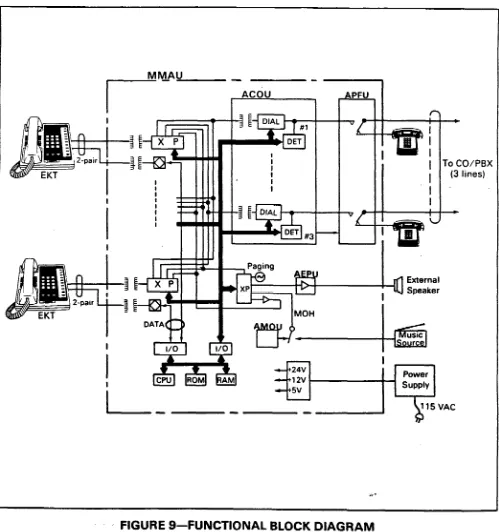
-05.02 A functio.nal block diagram of the
Strata S MKSU is shown in Figure 9; it con-
sists of the main PCB (MMAU), which includes a
station interface and central control equipment,
and a CO interface (ACOU). The optional Paging
Amplifier module (AEPU), internal music-on-hold
.source (AMOU), and Power Failure module(APFU) are also shown.
05.03 Connections between the station voice
GENERAL DESCRIPTION ‘. SECTION 100-003-l 00
JULY 1994
lines and the CO lines are via theswitching matrix
provided on the MMAU. A similar matrix is pro-
vided on the MMAU for intercom connection, pag-
ing connections and for the distribution of the
various system tones (Dial, Busy, etc.). .
05.04 The system is under the control of a
single-chip microprocessor, which is located, along
with the system programs and data memories, on
the MMAU PCB.
MM-AU
I---- -ncou - --z-I
-
I
To CO/PBX
1 (3 lines)
-
DATA
. . -
115VAC
b
FIGURE 9-FUNCTIONAL
BLOCK DIAGRAM
GENERAL DESCRIPTION
SECTION 100-003-l 00
JULY 1984
e..
06 SYSTEM CONFIGURATION
06.00 Key Service Unit
06.01 Completewith all options, the MKSU util- izes five circuit boards. The names and functions of the PCBs are:
ACOU (MF or DP):
An interface between the MKSU and the pub- lic telephone network or PBX lines. Ring detec- tion, hold and dial outpulsing for three circuits are performed by this PCB. Depending upon local CO requirements, an MF or DP type of ACOU will be provided (MF for DTMF outpuls-
ing; DP for rotary dial outpulsing). MMAU:
The main PCB of the MSKU, consists of the following four functions:
a) Station Interface-An interface between the MKSU and EKTs, which includes the solid-state space division matrix used for voice connections between the EKTs .and the CO/PBX lines. Two-pair wiring is required for each EKT; one pair carrying voice and the other pair carrying data to and from the EKT.
b) Control-All system control functions are performed by the single-chip micro-pro- cessor. The system program stored in ROM, the RAM for system operations, and the RAM for system data storage are also located on this circuit board.
c) Tone-Performs a number of miscel- laneous system functions:
l Generates system tones.
0 Provides the switching matrix for the delivery of tones for both paging and intercom connections.
l Houses the interface for the external
paw.
l Houses the interface for music-on-hold.
d) Power Regulating-Performs the following:
l Provides connection points for the 24
VDC input power.
l Houses the voltage regulators that pro-
vide 12 and 5 VDC for system operation.
l Houses a circuit breaker that protects
the 24 VDC, EKT, and MKSU circuits. AEPU:
An optional 3-watt amplifier for external paging.
AMOU:
An optional music-on-hold source. APFU:
An optional power failure transfer module used to transfer the CO lines to single line telephones in the event of a power failure. 06.02 The MKSU arrangement illustrated in Figure 10 shows the locations of the various PCBs. The MMAU, which hosts the ACOU, is secured to the MSKU with six screws. The ACOU, attached to the MMAU with four screws, is connected to it via four 1 O-pin connectors.
FIGURE lo-MKSU
(Interior)
06.03 The optional AEPU is attached to the MMAU with two screws, and connected with the MMAU via two lo-pin connectors.
06.04 The optional music-on-hold source (AMOU) is secured to the MKSU right side panel, and connected with the MMAU via a 3-pin connector.
06.05 The optional power failure transfer unit (APFU) is secured to the MKSU right side panel and connected with the ACOU via four 2-pin connectors.
06.10 Power Supply Assembly
-..06.12 An optional battery back-up unit (PBBU)
is available for the MPSA-200. With the optional
battery back-up assembly installed, all functions of
the Strata S system. will continue to operate
for several hours (the actual time period is in direct ratio to the type and size of batteries selected) after a loss of normal electrical power. No calls will be
disconnected during switch-over to battery power.
FIGURE 1 l-l
O-key “S” EKT
06.20 Station Equipment
06.21 The principal components of the lo-key
“S” electronic key telephone (Figure 11) are:
handset, dial pad, speaker, sliding ringing/speaker
volume control, 3-position volume control, one
intercom key, three CO/PBX line keys and nine
feature keys. LED indicators _- -. are provided for all
keys except FOLD] and [m%] keys. With the
exception of the three permanently dedicated
keys, the feature keys can be assigned to one of
two modes by programming (see Figure 12).
06.22 Standard features of the 1 O-key “S” EKT
include, among other standard features, paging,
one-touch automatic dialing keys, and auto-redial.
In initialized mode, three of the keys are utilized for
CO/PBX lines, one for intercom access, four keys
for one-touch automatic dialing and one each for
Do Not Disturb and Message Waiting/Flash.
GENERAL DESCRIPTION
SECTlON 100-003-l 00
JULY 1994
1 O-key 1 O-key 20-key 20-key 20-key
#l #2 #I #2 #3
FIGURE 12-KEY
LAYOUT
06.23 The optional lo-key EKT (Figure 13) pro-
vides the same programmable feature keys as the
standard EKT. plus a microphone control keym,
handsfree answerback and full speakerphone
capability.
I I
FIGURE 13-l
O-key EKT
GENEML DESCRlPTlDN SECTION 100-003-l 00 aJ~lY 1994 _ _
06.24 The optional lo-key BLF EKT (Figure 14) provides the same features as those listed in Para- graph 06.23, plus an LED indication on which stations are in use.
I
- : . .
06.26 All EKTs feature modular handset cords and are connected to the system via 4-conductor modular line cords.
. .
06.27 All EKTs are easily converted for wall mounting with an optional kit.
06.30 Installation
06.31 External devices are connected to the MKSU via connectors and terminals on the side panels.
FIGURE 14--BLF
EKT
06.25 The optional 20-key EKT (Figure 15) pro- vides the same features as those listed in Para- graph 06.23, and has ten additional feature keys. That is, three CO/PBX keys, one intercom key, and 16 feature keys that may be used as automatic dialing keys, direct station selection (DSS) keys, etc. Three different combinations of feature keys may be selected via programming, as shown in Fiaure 12.
07 FEATURES and OPERATION
FIGURE 15-20-key
EKT
a)
b)
cl
CO/PBX lines are connected to the MKSU right side panel via a 3-pair modular cord. The station connection points are extended from the MKSU to the MDF using one cable equipped with a standard 50-pin amphenol- type connector. The individual EKTs are con- nected to the MDF with 2-pair station cable. Screw-terminal barrier strips are mounted on the side of the MKSU to provide attachment points for the following connections:
24 VDC power input (left side)
Music-on-hold source input (right side) -. External page output (right side) ?4 06.32 The power supply is mounted to the well’ separately from the MKSU and connected to the 24 VDC input on the MKSU left side.
06.40 Maintenance
06.41 Faults in Strata S are repaired by replacing any faulty component (EKT, printed cir- cuit board, sub-assembly, etc.) and returning it to the manufacturer for repair.
07.00
General
07.01 This section contains brief descriptions of the
Strata
Sfeatures listed earlier in Tables B and C and some associated operating instructions. Detailed operating instructions can be found in either the Strata S USER GUIDE or Operat- ing Procedures. Section 100-003-4C0,Strata
S Jnstallation and Maintenance Manual.
07.10
Standard Features
07.11
System
All Call Voice Page:
Dialing a 1 -digit access code permits a station user to page via all EKT speakers and (option- ally)the External Page speaker simultaneously.
--.Alternate Point Answer:
CO/PBX or intercom calls can be answered from any station.
Automatic Dialing-System:
This standard feature allows 40 numbers to be stored in the system memory. After selecting an outgoing line, any station user can cause one of the stored numbers to be outpulsed by dialing the proper address code.
Automatic Hold Recall:
A CO line placed on hold by any station will recall that station after a programmable period of time.
Automatic Privacy:
Privacy is automatic on all connections. Automatic Release from Hold:
The system automatically releases held CO lines if a disconnect signal is received from the central off ice.
Busy Override:
After dialing a busy station and receiving a busy tone, the caller can dial a
q
and cause a tone burst to be sounded via the called EKT speaker.Conference-Multi-station (non-amplified):
Conferencing is permitted to a maximum of four stations and one CO or the intercom line. Conference-Multi-trunk (non-amplified):
Conferencing of two CO lines and three sta- tions is permitted.
Distinctive Ringing:
CO line and intercom calls are distinguished by different ringing tones.
DTMF and Dial Pulse Compatible:
DTMF or dial pulse signalling can be sent to the CO/PBX line by installing the proper ACOU PCB type.
External Page Interface:
A 6OD-ohm connection point is provided for a customer-provided external speaker. An am- plifier is also required, which can be mounted externally, or the AEPU (see Paragraph 07.20, External Page Amplifier) can be mounted in the MKSU. If the AEPU is used, the output impedance is 8 ohms. This page circuit is accessed as part of the All Call Voice Page - feature.
GENERAL DESCRIPTION SECTION 100-003-100
JULY 1984 Flash Key (PSX Transfer or CO Dial Tone Recall):
All EKTs are equipped with a Message Wait- ing/Flash m) key which, when operated while connected to a CO/PBX line, causes a timed “flash” to be transmitted to the CO or PBX. The timing of the flash can be pro- grammed to signal a PBX for feature operation or can be long enough to cause a disconnect and dial tone recall on a CO line. Also see Message Waiting.
Flexible Line Ringing Assignment:
A programmable ring or no ring option is pro- vided for each line selectively by each station. Each line may be programmed to ring all eight stations.
Live System Programming:
Live system programming is accomplished without service interruption to other station users by placing the system in the special pro- gramming mode and inputting data via station 17. Station 17 is the only station that is “down” during programming.
Message Waiting:
The designated Message Cent‘er can indicate a message is waiting for any station with the Message Waiting LED of that station. Also see Flash Key.
Music-on-hold Interface:
An interface is included for a customer-pro- vided external music source (see Paragraph 07.20, Music-on-hold Source). CO lines placed on hold will be connected to this source. Night Transfer:
CO lines can be programmed to ring different stations while in the “Day” or in the “Night” mode. If this feature is to be used, the w (Do Not Disturb) key on station 10 is reas- signed to the NT function and is then used to select the “Day” or “Night” mode.
Non-blocking Dialing:
Dialing is permitted on the intercom and all three CO lines simultaneously.
Outgoing Call Restriction:
Any station can be selectively restricted from originating calls on any or all CO lines. How- ever, the station will still receive calls on the restricted line(s).
PBX Compatible: +a-
Strutu
Sfeatures, such as toll restriction and automatic dialing, are compatible withPBX operation.
GENERAL OESCRlWlON SECTION 100-003-l 00 JULY 1984
e..
- Private CO Lines:
Restrictions may be programmed into the sys- tem so that selected CO line(s) may appear only on selected station(s).
Repeat Last Number Dialed:
The last number dialed by each station is always stored by the system and will be dialed automatically whenever the station user selects an outgoing line and depresses the
q
key. Toll Restriction:Selectively programmed on a per-station, per- line basis. Strata S performs toll restric- tion by rejecting the numbersa andm as the first or second digit and limiting the total number of digits dialed to seven or eight. Voice or Tone Signalling:
A programmable system feature that option- ally selects either tone ringing or voice page as the primary method of intercom call signalling. The calling station, however, may choose the alternate method by dialing a following the station number.
Wall Mountable MKSU:
The MKSU is designed for wall mounting only. 07.12 Station
Automatic Dialing-Station:
Each EKT can store a private list of ten fre- quently used telephone numbers.
Automatic One-touch Dialing (Programmable): This feature can be used with an EKT that includes m keys in its programmed as- signments.
a) A station number can be stored at each m key.
b) A number stored in the memory can be sent over a CO line by depressing the appropriate a key after accessing the CO line.
NOTE:
Each a key is counted as one of the 10 possible stored numbers available to each
station. Do Not Disturb:
This feature is activated and deactiited by alternate depressions of the m key. A sta- tion calling a station that is in the DND mode
will receive a fast busy tone.
Do Not Disturb Override (Programmable Option): After reaching a DND station, that station may be advised that a call is waiting by dialing
q
. A tone signal will be heard at the DND station. Executive Override of Privacy:A station that is programmed for this feature will override the automatic privacy feature and enter any existing conversation within the sys- tem. A warning tone, however, is inserted before the overriding station is actually con- nected. A maximum of two stations can be programmed for executive override.
l-called Illumination:
A distinctive flash appears on the intercom LED at the EKT that is actually being called. l-hold Illumination:
The EKT user is shown a distinctive LED flash to indicate a line actually placed on hold at that EKT. All other stations see the usual on-hold flash.
l-use Illumination:
A distinctive flash rate shows the line pres- ently in use at a given EKT. Other stations see a steadily illuminated LED for that line. Modular Handset and Line Cords:
All EKTs are equipped with modular handset and line cords.
On-hook Dialing:
Strata S lets you dial your calls with the
handset still on-hook. Call progress can be heard via the telephone speaker; no need to pick up the handset until your party answers. Push-button Dialing:
All Streta SEKTs are equipped with push-
button dial pads. Ringing Line Preference:
A line ringing at a station can be answered by merely lifting the handset or depressing the m key (optional speakerphone EKTs only). The ringing line will be automatically selected. 07.20 Optional Features
1 D-key EKT with Speakerphone:
An optional EKT provides handsfree answer- back and full speakerphone capability.
Busy Lamp Field (BLF) El&
An optional lD-key EKT provides handsfree answerback, full speakerphone capability, and an LED panel showing the busy/idle
status
off a-
GENERAL DESCRIPTION SECTION 100-003-l 00
JULY 1994 each station. A station in the DND mode will
show as busy. ZO-key Executive EKT:
An optional executive unit provides handsfree answerback, full speakerphone capability and, via 10 additional feature keys, automatic dial- ing access, four one-touch automatic dialing telephone numbers, redial last number dialed, a pause key, or may be used as a DSS station. External Page Amplifier:
This optional external page 3-watt amplifier (AEPU PCB) allows a customer-provided ex- ternal speaker to be accessed in an all-call operation by dialing non the intercom (see Paragraph 07.11, External Page Interface). Handsfree Answerback:
All optional EKTs are equipped for handsfree answerback on voice-announced intercom calls.
Microphone Control Key:
All optional EKTs have a 1-1 key that ’
may be used to cut off the microphone when the speakerphone is in use, thereby permitting a private local conversation. _
Music-on-hold Source:
This optional electronic music source (AMOU PCB), when installed. illiminates the need for a custome.r-provided external music source and provides electronic-generated music to CO lines placed on hold.
Speakerphone:
All optional EKTs are fully functional speaker- phones.
System Battery Back-up:
An optional PCB can be plugged into the MPSA-200 power supply to provide automatic switching to standby battery power. During
normal power conditions the batteries are kept fully charged by the power supply.
Wall Mounting Kits for EKTs:
All Strata S EKTs are easily converted for wall mounting with optional kits.
,. -
-
TOSHIBA SYSTEM PRACTICES
ELECTRONIC KEY TELEPHONE SYSTEM
INSTALLATION SECTION 100-003-200
JULY 1984
,
StrataS
--.
INSTALLATION SECTION 100-003-200
JULY 1984 TOSHIBA SYSTEM PRACTICES
ELECTRONIC KEY TELEPHONE SYSTEM _..
Strata
S
INSTALLATION
INSTRUCTIONS
TABLE of CONTENTS
PARAGRAPH SUBJECT PAGE
01 02 02.00 03 03.00 03.10 03.20 03.30 04 04.00 05 o:.:o 06.10 07 07.00 07.10 07.20 07.30 07.40 08 08.00 08.10 09 09.00 09.10 09.20 09.30 10 10.00 10.10 10.20 10.30 10.40 11 11.10 12 12.00 12.10 12.20 13 13.00 13.10 13.20 13.30 13.40 13.50
TABLE of CONTENTS ...
ILLUSTRATION LIST
GENERAL . .... . ..I :: : : : ::: : :: ::: : ::: ::: : ::
PACKING ...
Inspection
MKSU LOCATlON’REdlJiREMENTS’ : : : : : : : : : : : : : : : : : : : : : :
Power Requirements ...
Ventilation Requirements ...
Environment Factors ...
Cabling Considerations ...
MKSU MOUNTING
Wall Mounting theMKSU ’ : : : : : : : : : : : : : 1 : : : : : : : : : :
PRINTED CIRCUIT BOARD DESCRIPTIONS
OPTION SELECTION ... : : : : : : : : : : : : : : : : : :
External Page Option Selection ...
Music-on-hold Option Selection
PCBINSTALLATION ... . . . .
General Information ...
AMOU (MOH Source) Installation ... ) ...
APFU (Power Failure Transfer Unit) Installation ... : : .
AEPU (External Page Unit) Installation ...
MKSU Cover Installation ...
POWER CONNECTION ...
Cable Connection ...
Test Procedure
CABLECONNECTIONS - : : : : : : : : : : : : : : : : : : : : : : : : : : :
MDF Configuration ...
Station Cable Connection ...
Intercom Code Assignment ...
CO Line Connection ...
EKT INFORMATION ...
General ...
lo-key S EKT Wall Mounting ...
Optional EKT Wall Mounting ...
Installing the Handset Hanger Kit ...
EKT Connections
SYSTEM POWER-UP INITIAL& . : : : : : : : : : : : : : : : : : : : : : : :
Clearing Automatic Dialing ...
SYSTEM TEST PROCEDURES
lo-keys EKTFunctional Check’ : : : : : : : : : : : : : : : : : : : : : :
Optional EKT Functional Check ...
Feature Check
MISCELLANEOUS EQljlPMENT%NhiECTiONS ’ : : : : : : : : : : : :- : : : :
Wiring Connections ...
Music-on-hold Source ...
External Paging Connections ...
Direct External Speaker Connection ...
External Amplifier Connection se-
PowerFailureTransfer . ..::::::::::::::::::::::
i ii 1 1 1 1 1 1
1 ’
1 1 1 2 2 2 3 3 3 3 4’ 4 5 5 5 5 6 6 7 7 7 7 7 10 10 11 12 12 12 13 13 14 15 15 15 15 15
15 -.
TOSHIBA SYSTEM PRACTICES
ELECTRONIC KEY TELEPHONE SYSTEM
INSTALLATION SECTION 100-003-200
JULY 1984
w..
NUMBER
1 2 3 4 5 6 7 8 9 10 11 12 13 14 15 16 17 18 19 20 21 22 23 24 25 26 27 28 29 30
:: 33 34
Strata
S
INSTALLATION
INSTRUCTIONS
ILLUSTRATION LIST
TITLE PAGE
SideCovers ... 2
WallMountedMKSU ... 2
MKSUwith PCBs ... 2
External Pagelerminals ... 3
MMAUSwitches ... 3
MKSUCoverScrews ... 3
MountedAMOUPCB ... 4
AMOU/MMAU Cable Connection ... 4
MountedAPFUPCB ... 4
APFU Connection ... 4
Mounted AEPU PCB ... 5
System Diagram ... 6
MKSU Cable Clamping ... 7
MDF/EKT Wiring ... 8
RJ25C Wiring ... 7
1 D-key “S” EKT ... 9
1 O-key Speakerphone EKT ... 9
BLFEKT ... 9
20-key EKT ... . ... 9
KeyLayout ... 10
Wall Mount Bracket ... 10
BracketSlots ... 10
“S” EKT Wire Routing ... 11
Removing Optional EKT Base ... 11
EKT Wire Access ... 11
EKT Wire Routing ... 11
Handset Hanger Kit ... 12
SET Switch . _ ... 12
MKSU Connection ... 15
MMAU SW3 Switch ... 15
MMAU SW2 Switch ... 16
AEPU Volume Switch ... 16
Power Failure Transfer Diagram ... 16
PFf Telephone Connections ... 17
--.
01. GENERAL
I
01.01 This section describes the installation
procedures necessary to ensure proper operation
of the
Strata
S
system.02
PACKING
02.00 Inspection
02.01 When a Strata S system is received,
examine all packages and carefully note any vis-
ible damage. If any damage is found, bring it to the
attention of the delivery carrier and make the
proper claims.
02.02 Check the number of cartons and the
contents of the Strata S shipment against the
purchase order and packing slip. If it is determined that any cartons are missing, contact your delivery
carrier immediately. If it is determined that any
equipment within a carton is missing, contact your
Toshiba supplier immediately.
02.03 After unpacking (prior to beginning the
installation), inspect all equipment for damage. If
any damage isdetected, contact your delivery card
rier immediately. If possible, retain all original the packing material.
CAUTION:
When handling (installing, removing, exa-
mining, etc.) a printed circuit board. do not
touch the back (soldered) side or the edge
connector. Always hold a PCB by its edge.
03
MKSU LOCATION REQUIREMENTS
03.00 Power Requirements
03.01 The Strata S MKSU requires 24 VDC. This is provided by the power supply (MPSA),
which in turn requires power from a grounded
115 VAC outlet. The outlet should be protected
1 separately and rated at 15 amps.
03.02 The 54-inch cord provided to connect the
MPSA to the MKSU dictates the relative location
of the power supply. The power supply is also
equipped with a 10-h. AC power cord.
03.03 Two power supplies are available;
MPSA-200 and MPSA-512. The MESA-200 is used when battery backup power is required. 03.04 An optional battery backup unit (PBBU) is available for the MPSA-200. It is a printed circuit board that mounts inside the power supply hous-
INSTAUATION
SECTION 100-003-200
JULY 1994
ing. The recommended battery pack, which is
customer-supplied, consists of two maintenance-
free automobile 12 VDC batteries (maximum: 80-
amp/hour rating). With the optional PBBU assem-
bly installed, all functions of the Strata S
system will continue to operate for several hours
after a loss of normal electrical power (the actual time period is in direct ratio to the type and size of
batteries selected). No calls will be disconnected
during switch-over to battery power.
03.10 Ventilation Requirements
03.11 Sufficient ventilation should exist to allow
dissipation of the -heat generated by the power
supply and MKSU.
03.20 Environmental Factors
03.21 Humidity at the MKSU location should be
within 20 - 80% (without condensation), and the
temperature should be relatively constant within a
range of 32 - 122OF(O- 5OOC). In addition, expos-
ing the MKSU to an excessive amount of dust and
airborne chemicals may cause a failure-take this
into consideration during site selection.
03.30 Cabling Considerations
03.31 The MKSU must be located so that all
stations are within loo0 cable feet (305 m) of it.
Acceptable cable is 22 or 24 AWG inside tele-
phone station cable, jacketed but not shielded,
having two or more twisted wire pairs.
04
MKSU MOUNTING
04.00 Wall Mounting the MKSU
04.01 To mount the MKSU on the wall perform the following steps:
1)
2)
3)
4)
Remove both side covers from the MKSU (Fig- ure 1).
Hold the MKSU against the wall in its planned location and mark the screw locations through
the centers of the two keyholes on the upper
sides of the MKSU.
Lay the MKSU aside for the moment and start
two screws into the wall at the marked loca-
tions. Use l-W-inch panhead wood screws and stop when they have penetrated to half -. their depth. c*
Hang the MKSU on the two screws and start two additional screws in the lower two holes. Tghten all four screws.
INSTALLATION
SECTION
100-003-200
JULY 1994
5) Knockouts are provided on the top and bottom of the side covers to permit cables to enter the MKSU. Remove the appropriate knockouts.
FIGURE 1 -SIDE
COVERS
6) Reinstall the side covers.
7) Refer to Section 100-003-250, MPSA-512
Installation (or Section 100-003-255, MPSA-
200 installation), and follow the appropriate
instructions for installing the selected MPSA. A completed installation with an MPSA-512 should aooear as shown in Fiaure 2.
s--s
- 2
- .
FIGURE 2-WALL
MOUNTED
MKSU
05
PRINTED
CIRCUIT BOARD DESCRIPTIONS
05.01
A maximum of five PCBs can be installed‘.
in the MKSU. A maximum of one card of each type can be installed in the system (Figure 3). They are:
l MMAU (KSU Main Unit) l ACOU (Central Office Unit)
l Two types of ACOU are available:
a) MF-used when DTMF outpulsing is required.
b) DP-used when rotary dial outpulsing - is required.
l AMOU (Music-on-hold Source)
l Installed when Music-on-hold feature is
required without an external music source. 0 APFU (Power Failure Transfer Unit)
l Provides a switch-over of all CO/PBX lines
to dedicated, customer-provided standard telephones upon power failure.
l AEPU (3-watt External Page Amplifier Unit) l Installed when the External Page feature is
required with no external PA amplifier. The MMAU and ACOU PCB are factory-installed in the MKSU.
FIGURE 3-MKSU
WITH PCBs
06
OPTION SELECTION
06.01 The external pag? output appears at the -- terminals labeled 8/6OOkn the MKSU right side
panel (Figure 4). The output impedance can be -. selected to be either 8R or 6OOR. and is facton/- : set for 6OOR. In the 6OOR mode an external PA
_..
amplifier is required. Eight ohms is used when the AEPU PCB is installed. The output will then be via
a 3-watt amplifier on the AEPU.
FIGURE 4
EXTERNAL PAGE TERMINALS
06.02 External page options are selected using the SW2 switch located on the MMAU (Figure 5). Decide if the 8 or 6DOQ impedance is required and then make the selection by positioning SW2 to “8” or
FIGURE 5-MMAU
SWITCHES
06.10 Music-on-hold Option Selection 06.11 A customer-provided MOH program source or the optional AMOU PCB may be used. The AMOU provides a source of synthesized music.
06.12 The MOH option is selected using the
‘.. INSTALlATlON
SECTION 100-003-200 JULY 1984 SW3 switch located on the MMAU (Figure 5). SW3 is factory-set in the MOH position for use of an external program source. Move SW3 to the side marked MOU if the AMOU PCB is to be used.
07
PCB INSTALLATION
07.00 General Information
07.01 The MMAU and ACOU PCBs are factory- installed in the MKSU.
07.02 If any of the optional PCBs (AEPU, AMOU or APFU) are required, the MKSU top cover must be removed as follows:
1) Remove both side covers by swinging them to the left or right, as necessary, and then lifting them straight up.
2) Remove the three screws from the MKSU left side per Figure 6A.
3) Remove the two cable straps and three screws from the MKSU right side per Figure 6B.
FIGURE 6-MKSU
COVER SCREWS
4) Lift the MKSU cover,&.
07.10 AMOU (MOH Source) Installation 07.11 Secure the AMOU to the lower part of the MKSU right side panel with the two screws pro-
INSTALLATION
SECTION 100-003-200
JULY
1994v..
vided, as shown in Figure 7.
FIGURE 7-MOUNTED
AMOU PCB
07.12
Connect the AMOU cable toPB
on the MMAU PCB Der Figure 8.FIGURE 8
AMOWMMAU
CABLE CONNECTION
07.20
APFU (Power Failure Transfer Unit)
Installation
07.21
Secure the APFU to the upper part of the MKSU right side panel with the two screws pro- vided, as shown in Figure 9.07.22 Connect the 8-pin jack (from the OPL jack) into the
Pl
plug on,the APFU (Figure 10).FIGURE g--MOUNTED
APFU PCB
07.23 Refer to Figure 10 and connect the four 2-wire jacks from the APFU to their respective plugs on the top and right side of the ACOU as follows:
APFU ACOU
WHT, Bu( (Power) P8
RED, GRN (CO 1) PS
YEL BU( (CO 2) PlO
BLU, WHT (CO 3) Pll
FIGURE lo-APF&j
CONNECTIONS
--.-
07.30
AEPU (External Page Unit) Installation
07.31
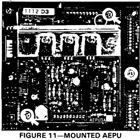
The AEPU is installed in the positione..
shown in Figure 11. Mount the PCB on the lo-pin connectors P5 and P6 (note the “6” arrow on the AEPU and pin alignment when positioning the PCB) and secure it with the two screws provided (Figure 11).
FIGURE 1 l-MOUNTED AEPU
07.32 Note the location of the volume control in Figure 11. It will be necessary to leave the MKSU cover off until this has been adjusted per Para- graph 11.30.
07.40 MKSU Cover Installation
07.41 Reinstall the MKSU top cover in the
reverse order the instructions in Paragraph 07.02. 08 POWER CONNECTION
08.00 Cable Connection
08.01 Plug the power supply into a 115 VAC
outlet and check its output voltage to be sure it is between 23.2 - 28.2 VDC. If the voltage is not within these limits, replace the power supply before proceeding.
IMPORTANT:
On the MPSA-512, verify that the power
switch is ON-it will be illuminated
08.02 Disconnnect the power supply from the 115 VAC outlet. Remove the plastic protective cover from the power terminal strip on the MKSU left side panel, and, with the supplied cord, con- nect the “+24V”, “OV” and “G” terminals on the power supply to the corresponding terminals on the MKSU. Secure the DC cord to the MKSU using the plastic cable clamp provided.
INSTALLATION SECTION 100-003-200
JULY 1984
IMPORTANT:
On the MPSA-200 and the MKSU. these
terminals are titled **+24V’-, ‘OV”qd “E “.
respectively.
08.03 The Toshiba Strata S electronic key telephone system requires a solid earth ground on the “E” terminal on the MKSU left side panel. Failure to provide such a ground may lead to con- fusing trouble symptoms in the system and, in extreme cases, circuit board failure. In most instal- lations, within the continental United States, the ground provided by the “third wire ground” at the commercial power outlet will be satisfactory for all Strata S requirements. However, in a small percentage of installations this ground may be installed incorrectly. Therefore, prior to installing a Strata S system, the third wire ground must be tested for continuity by either measuring the resistance between the 3rd prong terminal (earth ground) and a metal cold water pipe, or by using a commercially available earth ground indicator. If neither procedure is possible, then the test proce- dures outlined in Paragraph 08.10 should be performed. .
WARNING!
Hazardous vottage that may cause death or
injury is exposed during the following test.
Use great care when working with AC
po werline voltage.
08.10 Test Procedure
1)
2)
3)
4)
5)
Obtain a suitable voltmeter and set it for a possible reading of up to 250 VAC.
Connect the meter probes between the two main AC voltage points on the wall outlet. The reading obtained should be 90 - 130 VAC. Move one of the meter probes to the 3rd prong terminal (GND). Either the same reading or a reading of 0 volts should be obtained.
If the reading is OV, leave one probe on the GND terminal and move the other probe to the 2nd voltage terminal. If a reading of OV is obtained on both voltage terminals, the outlet
is not properly grounded. Omit steps 5 - 7,
and proceed directly to step 8.
. If a reading of OV onone terminal and a read- ing of 80 - 130 VAC on the other terminal is not obtained, the outlet is not properly grounded. Omit steps 6 & 7, and proceed directly to step 8.
INSTALLATION
SECTION 100-003-200
JULY 1994
-..
-
6) If a reading of OV on one terminal and a read-
ing of 90 - 130 VAC on the other terminal is
obtained, remove both probes from the outlet.
7) Set the meter on the “OHMS/Rxl” scale,
place one probe on the GND terminal and the
other probe on the terminal which produced a
reading of OV. A reading of less than IS2
should be obtained. If a reading of more than
1 R is obtained, the outlet is not adequately
grounded.
8) If the above tests show that the outlet is
Strata S system is connected.
08.11 Ensure that the power switch on the
MKSU is
OFF,
then plug the power supply-into the115 VAC outlet and measure the voltage at the
MKSU input terminals. Correct any problems
before proceeding.
09
CABLE CONNECTIONS
09.00 Main Distribution Frame (MDF) Con- figuration
improperly grounded, that condition should be 09.01 One 66ML50 split connection block (Fig-
corrected by a qualified electrician (per Article ure 12) is recommended as the Strata Smain
250 of the National Electrical Code) before the distribution frame (MDFL
MKSU
-L- 115VAC
P-pair 2-0ai.I
FIGURE 12-SYSTEM
DIAGRAM
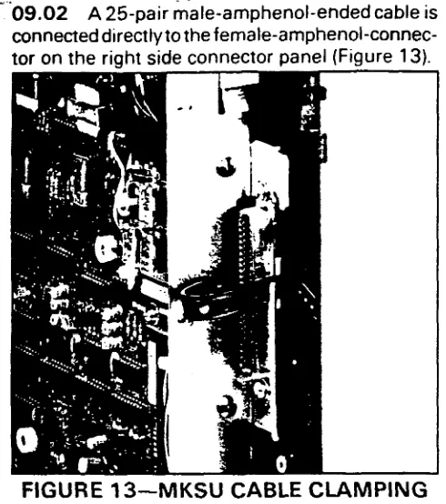
-‘09.02 A 25-pair &ale-amphenoliended cable is connecteddirectlytothefemale-amphenol-connec-
tor on the riqht side connector panel (Figure 13).
FIGURE 13-MKSU CABLE CLAMPING
09.03 Secure the cable to the panel using the
plastic strap and cable clamp provided.
09.04 Use the industry-standard color code
sequence and terminate the cable on the MDF
block as shown in Figure 14.
09.10 Station Cable Connections
09.11 Terminate the individual 2-pair station
cables consecutively on the MDF block; attach
them to the side opposite the MKSU cable. Use
bridging clips to connect the MKSU cable pairs to
the station cable pairs. Refer to Figure 14 for a
completed MDF block.
09.12 The cables used for station wiring should
be two twisted pair.
09.13 The overall length of the cable run must not exceed 1 DO0 ft. (305 m) for 24 AWG wire.
/MPORTANT:
When installing station cable, do not run
parallel to and within 3 ft. of an AC po wer
line. Such power lines should be crossed at
right angles (9OO) only.
09.14 At the station locations, terminate the station cable in a conventional 4- or 6-conductor modular station connector to accommodate the modular line cord from the EKT. The standard modular EKT cord length is 7 ft., while the maxi- mum allowed length is 25 ft.
‘k
INSTAUATION
SECTlON 100-003-200
JULY 1994
09.15 Figure 14 shows the EKT wiring ar-
rangement.
09.16 The various manufacturers of modular
station blocks have employed different color codes
to indicate the sequence of pairs in their blocks.
However, the color code most commonly used is
shown in Figure 14. Verify the configuration of
your modular blocks before connecting the station
cables.
09.20 intercom Code Assignment 7
09.21 Intercom codes are assigned perman-
ently to specific cable appearances in Strata
S. Make sure the station cables are connected to
the proper terminals (Figure 14).
NOTE:
White and blue (T3 and R3/ are not used for
Strata S station line connectors.
09.30 CO Line Connection
09.31 The CO/PBX tines are introduced into
the Strata Ssystem via a 6-wire modular line
cord (no longer than 25 ft.) conneqted directly to a
jack on the right side panel. The opposite end df
the cord then terminates directly into a locally-
rovided RJ-25C jack (Figure 15).
TO CO/PBX
n W a I -a 3 -a z ki -? a 4 -- RJ-25C JACK
r
-w--v---
1 6-POS.\T3 T2 Rl Tl R2 R3 / TO MKSU
FIGURE 15-RJ25C
WIRING
09.32 Secure the modular cord to the panel using the provided plastic cable ‘clamp.
10
EKT INFORMATION
10.00 General .
10.01 Four different Electronic Key Telephones
lNSTALl.ATlON '. SECTION 100-003-200
JlJlv1994
: I-pair JACKETED STATION CABLE
L
-El-l- Ynbu”
%R
“7r:
-c--i BRIDGING
-7 CLIPS
idOT USED I
66M160 SPLIT BLOCK
MODULAR STATION BLOCK
TO MKSU
II
5432
- .
I .... J
MODULAR
CORD STATION
l-IcjUHt 14-MUi- tK I WlHlNIj
(EKTs) may be used in the
Strata
system. The standard EKT (Figure 16). known as the 1 O-key “S” EKT, is equipped with three permanentlyded- icated keys and ten line/feature keys. The three optional (full speakerphone) EKTs are equipped with four permanently dedicated keys and either 10 or 20 feature keys: lo-key EKT (Figure 17). 1 O-key Busy Lamp Field (BLF) EKT (Figure 18) and 20-key EKT (Figure 19).10.02 The lO-key S EKT measures: Height: 3.5 inches (88.9 mm)
Width: 6.0 inches (152 mm) Depth: 9.0 inches (229 mm)
I. -
and is equipped with 13 line end feature keys in addition to its push-button dial pad. Three of the keys are utilized for central offiie/PBX lines, one
I
;
‘. _.
-.
I
FIGURE 16-l O-key “S” EKT
‘.. INSTALLATION
SECTION 100-003-200
JULY 1984
I
FIGURE 17-lo-key SPEAKERPHONE EKT
FIGURE 18-BLF EKT FIGURE 19-20-key EKT
for intercom access, and the remaining keys for
feature operation.
10.03 All three optional EKTs share the same
external dimensions:
10.05 The optional 1 O-key BLF EKT provides the
same features as those listed in Paragraph 10.04,
plus an LED indication on which stations are in
use.
Height: 4.0 inches (102 mm) Width: 8.8 inches (224 mm) Depth: 9.1 inches (230 mm)
Each is equipped with either 14 or 24 line and
feature keys in addition to a push-button dial pad.
Again, three of the keys are utilized for CO/PBX
lines, one for intercom access, and the remaining
keys are used for feature operation.
10.06 The optional 20-key EKT provides the
same featuresas those listed in Paragraph 10.04,
plus ten additional feature keys. That is, three
CO/PBX keys, one intercom key, and 16 feature
keys that may be used as automatic dialing keys,
direct station selection (DSS) keys, etc.
10.07 System software assignments permit
some variation to the feature keys on all four EKTs (see Figure 20 for key configurations).
10.04 The optional lo-key EKT provides the
same programmable feature keys as the standard
EKT, plus a microphone control key, handsfree
answerback and full speakerphone capability.
10.08 All EKTs feat_u_re modular handset cords -.
and are connected to the system via four-conductor
modular line cords. In addition, all EKTs may be
used at any or all stations.
INSTALLATION
SECTION 100-003-200
JULY 1994
. -
PAU
H
-FIGURE 20-KEY
LAYOUT
10.10 1 O-key S EKT Wall Mounting
10.11 An optional ‘SKWM” kit is required to
convert the IO-key S EKT for wall mounting. The
“SKWM” kit consists of a metal wall bracket and a handset hanger kit.
10.12 TheEKTmaybemountedonawallorany
other flat, vertical surface to which the wall bracket can be secured. When selecting the mounting site, consider the EKT weight and the additional stresses to which the mounting will be subjected.
10.13 Mounting screws or mollies, appropriate for the surface on which the telephone is to be secured, must be provided by the installer.
10.14 With the wall bracket the “S” EKT can be mounted to any suitable vertical surface or to a telephone outlet plaster ring (see Figure 21). Secure the wall bracket to the desired wall site, and use a spirit level, if necessary, to make certain the bracket is level.
10.15 The EKT is placed on the wall bracket by
1
FIGURE 21 -WALL
MOUNT BRACKET
mating the bracket’s four hooks (A-Figure 21) L with the four slots on the EKT base (B-Figure 22) and sliding the EKTdownward. The EKT is secured in position by bending the two tabs (C-Figure 21)
forward in order to orevent ubward motion of the. I. EKT.
I
FIGURE 22-BRACKET
SLOTS
10.16
Route the tail cord as shown in Figure 23. _. 10.17 Install the handset hanger kit per Para- graph 10.30.10.20 Optional EKT Wall Mounting
FIGURE 23-
“S” EKT WIRE ROUTING
10.21 An optional handset hanger kit (HWMA) is also required to convert the optional EKTs for wall mounting.10.22 All optional EKTs are mounted in the same manner, and they may be mounted on a wall or any other flat, vertical surface to which the base can be secured. When selecting the mounting site, consider the EKT weight and the additional stresses to which the mounting will be subjected. 10.23 Mounting screws or mollies, appropriate for the surface on which the telephone is to be secured, must be provided by the installer.
10.24 Locking tabs secure the EKT’s base. The direction in which the base is attached to the EKT determines whether it will be used as a desk unit or wall unit (it is factory-configured as a desk unit). Disengage the locking tabs by pushing downward on the base (Figure 24).
FIGURE 24
REMOVING
OPTIONAL EKT BASE
10.25 Refer to Figure 25, choose which of the
INSTALIATION
*-
SECTlON 100-003-200
JULY 1994
knockouts are appropriate for the tail cord route, and then cut them.
FIGURE 25-EKT
WIRE ACCESS
10.26 Secure the base to the desired wall site. Use a spirit level and make certain the top of the base is level and that the deeper portion is down. 10.27 Route the tail cord through the holes in the base and secure the EKT (Figure 26).
-I
FIGURE 26-EKT
WIRE ROUTING
10.28 Install the handset hanger kit per Para- graph 10.30.
10.30
Installing the Handset Hanger Kit
10.31
Refer to Figure 27, the optional handset hanger kit (available from your Toshiba supplier) must be used whenever an EKT is wall-mounted. (When ordering specify if “S” EKT or optional EKT-the HWMA is included in the SKWM kit.) The remainder of the installation is the same for all EKT types.10.32 Remove the -card cover by inserting a paper clip in the hole at one end. Bend the cover up and remove it and the number card.
INSTALLATION
SECTION 100-003-200
JULY 1994 . -
10.34 install the handset hanger into place and tighten the screws. Reinstall the number card and card cover.
FIGURE 27-HANDSET
HANGER KIT
10.35 An optional 13-ft. handset cord is avail- able from your Toshiba supplier, and it is sug- gested that this cord be used when wall-mounting an EKT.
10.40 EKT Connections
10.41 Connect the appropriate length line cord to the modular connector, route the cord to the EKT and connect to the EKT modular jack. Test the EKT per Paragraph 12.
11 SYSTEM POWER-UP INITIALIZE
11 .Ol The
Strcsta
S has a list of standard system data assignments stored in ROM that can be entered at any time by performing the initialize sequence outlined below. The system must be initialized when it is first installed. This will allow the system to be tested and any faults to be cor- rected before time is spent on programming.11.02
To initialize the system data memory, refer to Figure 28 and perform the following steps: a) Place the power switch on the MKSU in theON position.
b) Depress the SET switch and allow it to lock . SETLEDgoeson.
l MW/FL LED on station 17 goes on.
FIGURE 28-SET
SWITCH
c) Depress the m key on station 17.
l SPKR LED goes on.
d) Dial lqRm[ on the dial pad.
e) Depress the a and m keys.
l The corresponding LEDs go on.
f) Depress the IHoLD1 key.
l The LEDs on station 17 for intercom through
I. AD 4 begin flickering. ,
1. g) Depress and release the SET switch again.
. SET LED goes off. -
l Station 17 LEDs go off.
h) Cycle the MKSU power switch OFF and ON. 11 .l 0 Clearing Automatic Dialing
11 .l 1 The Automatic Dialing memon/ will con- tain random numbers when the system is powered up initially. To clear the memory; therefore pre- venting meaningless numbers from being dialed, proceed as follows:
a) Lock in the SET switch on the MKSU.
l The SET LED and MW/FL LED on station
17willgoon.
b) Depress the m key on station 17.
l SPKR LED will light steadily.
c) Dial mmrj on the dial pad.
l SPKR LED will flash continuously.
d) Depress the a and m keys. 0 The corresponding LEDs will light e) Depress the m] key.
l All station 17 LEDs &xcept MW/FL) will go Off.
f) Release the SET switch on the MKSU.