Siemens Practices
Installation Series
:
A30808-X5130-8120-1-8928
1
Issue 1, May 1986
’
1
!
Issued by Office Systems Group
5500 Broken Sound Boulevard N.W., Boca Raton, Florida 33431
--___________-Siemcns Information Systems, Inc.
SATURN IIE EPABX A 3 0 8 0 8 X 5 1 3 0 - 8 1 2 0 - 1 - 8 3 2 8
Installation Test Procedures Issue 1, May 1906
SECTION
PAGEl.CO INTRDCUCTlON . . .
;
. . . .1-l Purpose . . . l-l scope . . . 1-l Siemens SATURN IIE Practices . . . l-l Siemens Customer Support Services. . . l-l 2.00 PREP/%KGXIY ACTIVITY . . . 2 - 1Cener21. . . 2 - 1 Test Equipment Required. . . 2-l Handling Precautions for PC& with
MOS Integrated Circuiis. . . 2-l PC6 Removal and Replacement Guidelines. . . 2 - 1 Initial Visual Inspection Procedures. . . 2 - 1 3.CO GROUND TESTS . . . 3-l G e n e r a l . . . 3-l System Ground Test. . . 3 - 1 Shelf Ground Continuity Test. . . 3 - 1 4.00 POWER-UP TESTS . . . 4-l G e n e r a I. . . 4-1 Power-Up/Output Voltage Tests. . . 4-l 5.00 OPERATING PROGRAM
LOAD!NG
. . . 5 - 1 G e n e r a l . . . 5 - 1 Loading Operafing Dis!~. . . 5-l Inputting CMU Data to Floppy Disk. . . 5-l &CO ON-FINE DlAGrGxTlC TESTS . . . 6 - 3 G e n e r a l . . . 6-l Connection of Maintenance Phoneand Modem . . . 6-l MDF Cross-Connecting Prccedures. . . 6 - 1 System Diagnostic Tests; . . . 6-12 7.CO INSTALLATION TEST PRCCEDURES CHEC#L!ST 7-l
G e n e r a l . . . 7-l
l=lGURE
PAGE2.00 Signal Cab!e Distribution for the SATURN IIE System (Basic Cabinet). . . . 2.01 Signal Cable Distribution for the SATURN IIE
System (Expansion Cabinet). . . . 2.02 Power/Ground Distribution for the SATURN IIE
System (Basic Cabinet). . . . 2.03 Power/Ground Distribution for the SATURN IIE
System (Expansion Cabinet) . . . . 3.00 System Ground Test Connections
...
3.01 Shelf Ground Continuity Test Connections. . . . 4.00 Location of Input Voltage Connectors onBasic Backplane. . . . 4.01 Location of Input Voltage Connectors on
LTU Backplane . . . . 5.00 Floppy Disk and Storage Envelope . . . . 5.01 Power System Unit (Front View). . . . 5.02 Floppy Disk Loading Procedures. . . . 5.03 CIOP Printed Circuit Board . . . . 6.00 Maintenance Phone and Maintenance-Related
Cress-Connections . . . . 6.01 Modem Cross-Connections . . . .
.
2 - 4 2 - 5 2 - 6 2 - 7 3 - 2 3 - 3. .
4 - 5.
4 - 6 5-l 5-4 5 - 5 5 - 6 6 - 2 6-z6.02 Single -Line Telephone Cross-Connections
Using SLMA PCB . . . 6-3
6.03 Single -Line Telephone Cross-Connections U s i n g S L A i 6 P C B 6.04 Siemens Digital Teiephone Cross-Connections
U s i n g S L M D P C B . . 6.05 SATURN Attendant Console Cross-Connections 6 . 0 6 C O a n d CID T r u n k C r o s s - C o n n e c i i o n s . 6.07 Two-Wire (Type I) E&M Trunk Cross-Connec?ions 6.08 Four-Wire (T;lce I) E&M Trunk Cross-Connections
6 - 3 6 3 G - 4 E-5 G - 5 G - S
_.
6.09 Two-Wire (Type II) E&M Trunk Cross-Connections . 6-6 6.10 Four-Wire (?ype II) E&M Trunk Cross-Connections . 6-7 6.il Recorded Anncuncement (DID and Tie Trunk
Vacant Number Intercept, and ACD
A n n o u n c e m e n t Service) C r o s s - C o n n e c t i o n s 6 - 7 6.12 Code Ca!ling (With or Without Answerback)
Cross-Connections . . 6-8 6 . 1 3 D i a l C i c i a t i o n (DTMF) C r o s s - C o n n e c i i o n s . 6 - 8 6.14 Music-en-Hold Cross-Connections Using
TMBA4 PCB . . . . 6-9
6.15 Music-on-Ho!d Cross-Connecticns Using
SLMAISLA16 PCB . . . 6-9 6.16 Paging With Answerback Cross-Connections 6-10 6.17 Paging Without Answerback Cross-Connections. . 6-10 6.18 Universal Night Answer (UNA) Cross-Connections E-11 6.49 Attendant Conscie Keypad and Fcaturo
Button Depiassion Ssquonce G-:3 6 2 0 Siemens DYIiD Te!ephono Buttcn Ccpressicn
Sequence . . . 6-21 6.21 Siemens JR-DYAD Te!ephone Euitcn
Depression Sequence . . 6-23
1.00 Mnemonics Used in This Practice . . . l-l 2.CO PCB and Powar Supply Removal Guidelines . . . 2 - 2 2.01 Visual Inspeciion . . . 2 - 3 3.00 System Ground Test. . . 3-l 3.01 Shelf Ground Continuity Test . . . 3 - 1 4.00 Power-Up/Output Voitnge Test . . . 4-l 5.00 Loading Procedures fcr Operating Disk. . . 5 - 2 5.01 CIOP DIP Swiich Settings . . . 5 - 3 5.02 LED Display Values for Leading Errors . . . 5 - 4 6 . 0 0 T o n e G e n e r a t o r T e s t . . . 6 - 1 3 6.01 Tone Genera:or Test I\!umbers . . . G - i 3 6.02 DTMF Receiver Test . . . G - 1 4 6.03 Station Line Test. . . 6 - 1 4 6 . 0 4 D T M F P a d T e s t . . . 6 - 1 5 6 . 0 5 C o n s o l e T e s t . . . 6 - 1 6 6.06 Attendant Console Displayable Characters. . . 6 - 1 9 6.07 Siemens Digital Telephone - DYAD Button Test 6-20 6.08 Siemens Digital Telephone - JR-DYAD
Button Test . . . . . 6.09 Siemens Digiial Telephone -DYAD Display Test 6 . 1 0 S i e m e n s D i g i t a l T e l e p h o n e D i s p l a y a b l e
Characters . . 6 . 1 1 O u t g o i n g T r u n k T e s t . 6 . 1 2 P l a c i n g C i r c u i t ( s ) I n - S e r v i c e 6 . 1 3 T a k i n g C i r c u i t ( s ) O u t - o f - S e r v i c e 7.CO Insta!lation T e s t P r o c e d u r e s C h e c k l i s t
SATURN IIE EPABX installation Test Procedures
A30808-X5130-0120-l-0928
Issue 1, May 1986 .
1 . 0 1 Purpose. The equipment comprising the SATURN IiE (SATURN Ii-Expanded) System is compleYely tested at the fac-tory prior to shipment. The inspections and tests covered in this practice verify that the EPABX equipment has been properly installed; ensure that no damage wasIncurred dur-ing transit; and confirm that the sysiem is completely opera-tional. Table 1.00 defines the mnemonics usedthroughout i h i s practice.
CAUTION
lnstalbtion test procedures on the SATL’RN I/E EPABX must be performed only by Siemer;s cetiified personnel.
1 . 0 2 Sccpe. This practice is divided into the following sec-tions which are presented in the sequential order of per-for-m a n c e after initial installation of a SATURN IIE Systeper-for-m. When additional equipment is installed to an existing and active SATURN IIE System, it is the responsibility of craft person-nel to determine the sequential order of the test procedures contained in tihese sections.
ACD A u ; o m a i i c Cafl Disiribution
ALiVl Alarm
ASCII American Standard Code for Information lntarchange CIOP Controller/Input-Ouiput Prccessor
CMU Customer Memory Update
c o Central Office
CONF Conference Module
C O T Central Office Trunk
DCI Data Communication Interface
DID Direct Inward Dialing
D I P Dual lnline Package
D P Dial Pulse
D T E Da?a Terminal Equipment D T M F Dual Tone Multifrequency E I A Electronics Industries Association
E P A B X Electronic Private Automatic Branch Exchange
FDD Floppy Disk Drive
IRAM Input Random Access Memory
L T U Line/Trunk Unit
L T U P S Line/Trunk Unit Power Supply
LED Light-Emitting Diode
MCA Memory Control and Attenuation
MDF Main Distribution Frame
MEM3 25Gkb Memory
M E M 4 1Mb Memory
MOS Metal Oxide Semiconductor
MRA Material Return Authorization.
M S M Memory Support Module
M T C E Maintenance
00s Out-of-Service
O R A M Output Random Access Memory P A B X Private Automatic Branch Exchange
PCB Printed Circuit Board
P E N Port Equipment Number
PIMD Premium Instrument Module Digital PSC Parallel/Serial Converter
PSU Power Supply Unit
a. Section l.CO - Introduction b. Section 2.00 - Preparatory Activiiy c. Section 3.00 - Ground Tests d. Section 4.00 - Power-Up Tests
e. Section 5.00 - Operating Program Loading f. Section 6.80 - On-Lina Diagnostic Tesis g. Section 7.00 - lnstallaticn Test Procedures
Checklist
7 . 0 3 Siemens SATURN IIE Prac:iccs. The practices, issue numbers and dates for the SATURN IIE EPABX are lists3 in the P r a c t i c e s D o c u m e n t a t i o n I n d e x A.30808~X5130-AlgO- * E987 A l -ways refer to the !aiest issue of the application indcx to ob-tain the latest issue number of a practice.
7 2 4 S i e m e n s Cus;oma: Sqpsrt S e r v i c e s . Sicrnons maintains a nationwide network cf field service offices. Con-tact the Siemens regional oifice for any engineering es-sistance that may be requked.
TaS!e 1.00 Mnemonics Used in This Practice DEFiN1TfON
SATURN IIE EPABX Installation Test Procedures
.
Table 1.00 Mnemonics Used in This Practice (Continued)
[\fiNEMDNIC * D E F I N I T I O N
R A U P Remote Access Unit/Ports
RGEN Ring Generator
S-416 Subscriber Line Module Analog - 16 lines SLMA Subscriber Line Module Analog
SLMA-S Subscriber Line Module Analog - Station SLMD Subscriber Line Module Digital
S M X T G Signal Multiplexer/Tone Generator SPC Stored-Program-Controlled
S P G Single Point Ground TMBA-2 Two-Wire E&M Trunk TMBA-4 Four-Wire E&M Trunk TMBM Central Office Trunk T M I E Direct Inward Dialing Trunk TMS Transmission Measuring Set T S T A P P Test - Apparatus
TSTDIAG Test - Maintenance Diagnostic
T T Y Teletypewriter
UNA Universal Night Answer
ZUNA Zoned Universal Night Answer -48PS -48Vdc Power Supply
SATURN IIE EPABX A30808-X5130-B120-l-8928
Installation Test Procedures Issue 1, May 1986
2 . 0 1 General. This section describes the test equipment re-quired to perform the installation test procedures, handling precautions for Printed Circuit Boards (PCBs) with Metal Ox-ide Semiconductor (MOS) integrated circuits, guOx-idelines for removal and replacement of PCBs and powei supplies, and initial visual inspection procedures.
2.02 Test Equipment Required. The following test equip-ment is required to perform the procedures contained in this practice:
a. Digital Multimeter. A digital multimeter of gocd com-mercial quality with an accuracy of + 1.0% or better. The digital multimeter is used to perform the ground tests and output voltage tests.
b . Maintenance Test Phone. For both Dial Pulse (DP) and Dual Tone Multifrequency (DTMF) systems, a lineman’s test set or a single line te!ephone. A modular jack (MTCE PHONE) is provided on the front panal of the PSU for conneciing the maintenance test phone when equipped with a modular plug. When the maintenance test phone is not equipped with a modular plug, a sta-tion appearance can be used via the Main Distribu-tion Frame (MDF). The mainienance test phone is used to perform the on-line diagnostic tests.
c. Data Service Terminal. A Keyboard-Send-Receive (KSR) daia terminal equipped with a standard ASCII keyboard and an EIA RS-232C interface (Silent 700 Series - Model 743 KSR - Texas Instruments, or equivalent). The data service terminal is used to input installation dependent data (i.e., system data base) into system memory when the standard data base format is supplied with the SATURN IIE System.
d. -Transmission Measuring Set. A transmission measur-ing set (TMS) used to measure the transmission qual-ity of a trunk or station (Hewlett Packard HP-355iA or equivalent). Refer to the manual On-Line DiagnostiC Tests, Outgoing Trunk Test and Station Line Tosl.
2.03 handling Precautions for PCBs wifh MCS
Integmt-ed Circuiklt is important that craft personnel handling FCBs with MOS integrated circuits free themselves from electrostatic charge by touching a grounded cabinet frame before handling such PCEs, or by wearing grounded wrist straps. Failur:, to observe this practice may result in damage to M O 3 PCBs due to electrostatic discharge.
WARNING
lirazardous voltages exist r&h.% the eqo&ment cabins?. B e e x t r e m e l y c a r e f u l w h e n perr”orming fcsa-incjtroubleshooting p r o c e d u r e s with t h e oquipmcr;t panel(s) removed.
2 . 0 4 PCB Removal and P,ep!acemenZ Guide%% In many instances during testing, the corrective action for a procedure in which the proper verification was not obtained requires that a PCB or a power supply be removed and replaced with a spare. Tablo 2.00 provides the guidelines that shou!d be o!)-served when removing and rep!acing PCBs and powor SI:;X-plies in an active sysicm.
2.05 lnifial Visual kspactizn Procedurx. The visu’al in-spection procedures contained in Tab!e 2.01 must be psrfcrmcd to ensure that the equipment comprising the SATURN ItE Sys-tem has been properly installed and configured to meet the installation requirements. Before proceeding wiih the visual in-spections, the front, rear and side panels of the cabinei should be removed to allcw thorough inspection of the equipment.
-Table 2.00 PC3 and Power Supply Remcval Guidelines
I’AODIJLE OR SERVEC” SPECIAL
UNIT S T A T E INSTRUCTKWIS
CIOP NA
CONF . NA
DTMF 0 0 s
FDDO, FDDl NA
LTUC f NA
L T U P S l
NA MCA
MEM3 kz
M E M 4 NA
M S M l NA
MSM Baitery l NA
P I M D 0 0 s
PSC NA
PSU NA
RAUP NA
S L A l 6 00s
SLMA-0 0 0 s
SLMA-S 003
SLMD 0 0 s
S M X T G
ES TMBA-2
TMBA-4 0 0 s
TMBM 0 0 s
T M I E 0 0 s
-48PS.l NA
-48PSt f NA
* Optional depending upon customer/system requirements. NA = Not Applicable; 00s = Out-of-Service
Notes 1 and 2 Notes 1 and 2 Note 3 None Note 4 Note 5 Notes 1 and 2 Notes 1 and 2 Notes 1 a n d 2 Note 1 Note 6 Note 3 Notes 1 and 2 Note 7 Notes 1 and 2 Note 3 Note 3 Note 3 Note 3 Notes 1 and 2 Note 3 Note 3 No?e 3 Note 3 Note 8 Noie 3
Notes:
1 . System outage (halts call processing). Set BASIC PS circuit breaker on PSU to off.
2 . Open FDD and remove floppy disk before removing PCB. After new PCB is inserted, reinsert floppy disk, close FDD, set B A S K PS circuit breaker on PSU to on, and press reset switch on CIOP
3 . VVait for in-process ca!ls i0 complete.
4 . Removal places one-half of ports in shelf out-of-service.
5 . Before removal, set related LTUPS circuit breaker on PSU to off. Removal places all ports in shelf out-of-service. 6 . Battery may be replaced with power applied to system.
7. System outage (halts call processing). Before removal, set all circuit breakers to off, open FDDs and remove flop-py disks. After replacement, reinsert flopflop-py disks, close FDDs, set circuit breakers to on, and press reset switch on CIOR
8 . Set related circuit breaker on PSU to off. May halt call processing depending upon system configuration and traffic. If there are two -48Vdc power supplies (where system includes an Expansion Cabinei), the remaining sup-ply may have sufficient capacity to support system operation.
A30808-X5130-8120-l-8928 Issue 1, May 1986
I
.-A30808-X5130-B120-l-8928 Issue 1, May 1986 SATURN IIE EPABX
Installation Test Procedures
Table 2.01 Visual Inspection
S T E P VISUAL INSPECTION REFERENCE
1 Check that the cabinet ac power cord is not connected to an electrical outlet.
2 Check that the -48Vdc power supply is strapped for SATURN IIE EPABX Installation
11OVac or 22OVac. Procedures Practice (Section 4.00)
3 Check that all circuit breakers on the Power System Unit SATURN IIE EPABX Installation (PSU) are in the OFF position and fuses inserted. Procedures Practice (Section 4.00) 4 If the MSM is installed, check that the Battery Packk is not SATURN IIE EPABX Installation
connected but inserted into corresponding position. Also Procedures Practice (Section 4.00) check that the PSU is strapped for MSM operation.
5 Check that each PCB in the system is withdrawn from its backplane connector.
6 Check that the DIP switch settings for the CIOP board are set SATURN IIE EPABX Installation to meet the operating characteristics of the particular data Procedures Practice (Section 4.00) service terminal to be used to input the installation-dependent
data(i.e.,data base) into system memory when the standard data base format is supplied with the SATURN IIE System.
7 Check that each trunk-type PCB (i.e., T M E M , TMIE, TMBA-2 SATURN IIE EPABX Installation and/or TMBA-4) is properly strapped according to the Procedures Practice (Section 4.00) operating characteristics of the trunk facility of the Central
Office (CO) or distant PABX.
8 Chec!c that the intercabinet signal and power/ground cabling Figures 2.00 through 2.03 arrangements are complete and all connectors are firmly
seat-ed according to the referencseat-ed illustrations (Figures 2.00 through 2.03).
9 Check that Berg Clips are on pins 27 and 28 of unused SATURN IIE EPABX Installation signal cable connectors on basic shelf. Procedures Practice (Section 4.00)
w 3 w13
-I
I
SATURN IIE EPABX ,xtallation Test Procedures
A30808-X5130-B120-l-5928 Issue 1, May 1986
SATURN IIE EPABX Installation Test Procedures
A30808-X5130-B120-l-8928 issue 1, May 1986
W 2 3
EXPANSION CABINET \
I
---: ]
FDD
1
:
,
i;wi!
i-L--i--
-
_-__
LiTJ.
--r--- *
W 2 2
BASIC CA&NET
A5040-2.313186 Figure 2.01 Signal Cable Distribution for the SATURN IIE System (Expansion Cabinet)
SATURN IIE EPABX tnstallation Test Procedures
A30808-X5130-8120-1-8928 Issue 1, May 1986
LTUSO
LINE TRUNK UNIT SHELF J42
J43
r JP
L
Jl
BASS BASIC SHELF
E l a -J46 J47 E2
05039.1..wmG Figure 2.02 Power/Ground Distribution for the SATURN IIE System (Basic Cabinet)
A30808-X5130-B120-l-8920 Issue 1, May 1986
EXPANSION CABINET REF.
L --M--e--\-
-
-
-
-,-,
-BASIC‘CABINET REF.
A5U38-1-4:3:86
Figure 2.03 Power/Ground Distribution for the SATURN IIE System (Expansion Cabinet)
SATURN IIE EPABX A30808-X5130-B120-l-8928
Installation Test Procedures issue 1. May 1986
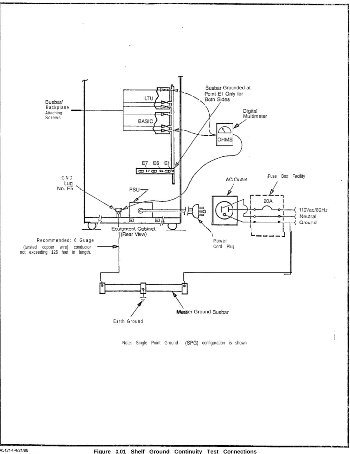
3 . 0 1 General. The SATURN HE System must be connected t o a n e a r t h g r o u n d ( i . e . , m e t a l l i c c o l d w a t e r p i p e o r m a s t e r g r o u n d busbar) in addition to the safety ground in the ac power cord. A G-gauge (twisted copper wire) conductor should be connect-e d b connect-e t w connect-e connect-e n t h connect-e g r o u n d i n g l u g E 5 l o c a t connect-e d o n t h connect-e b o t t o m o f t h connect-e cabinet frame and the snlccted earth ground (refer to Section 3.00 in the SATURN HE EPABX Installation Procedures prac-tice for details). The following tests must be performed to en-sure that proper earth ground connections have been accomplished, and that ground connections within the cabinet a s s e m b l y h a v e n o t b e e n d a m a g e d o r l o o s e n e d d u r i n g s h i p m e n t .
WARNiNG
Hazardous voltsgos txkt within the equipment csbinef. Ee
extremely ca-ej’Ll when performing t~s%i~g/l’roubiesh~oting procedures with the equipment panel(s) removed.
3 . 0 2 System Grcund Test. Before proceeding with the test’ procedures indicated in Table 3.00, check that the earth ground connections are secure and ground conductors are firmly positioned on grounding lug E5 at i h e bottom of the cabinet frame.
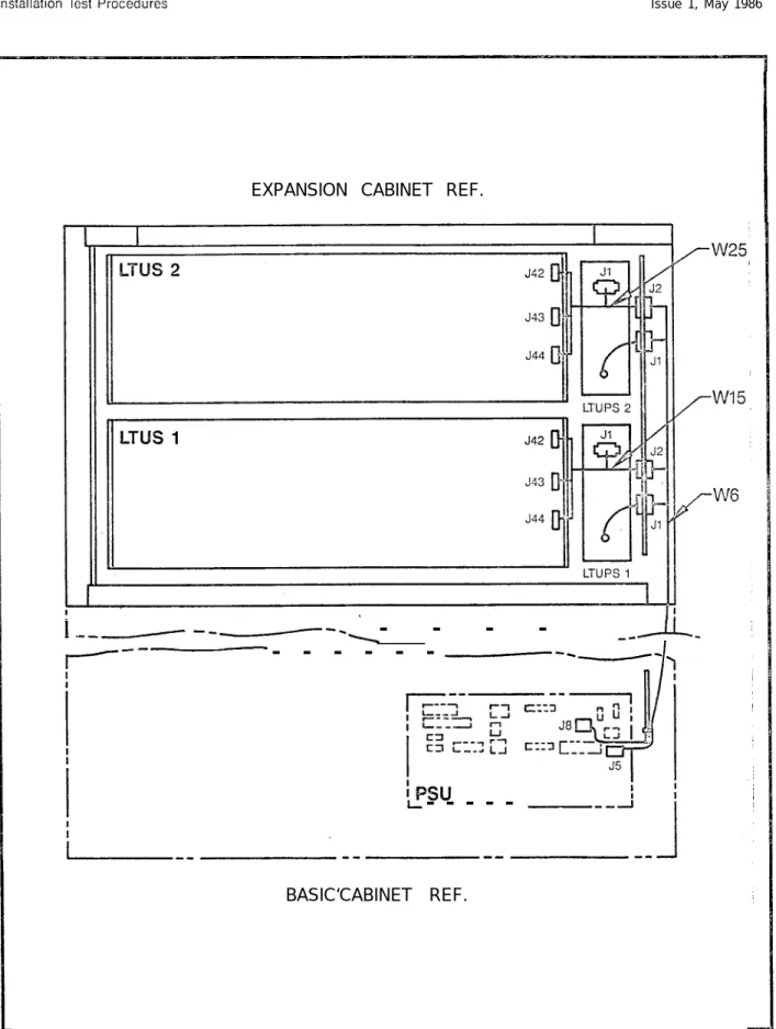
3 . 0 3 Shelf Ground Continuity Test. Each LTU shelf assem-bly within the cabinet assemassem-bly is grounded via two vertical busbars. Beiore proceeding with the test procedures indicat-ed in Table 3.01, check that each shelf backplane is iniercon-netted with the busbar flanges and adequately secured into position.
Table 3.00 System Ground Test
PROCEDURE VERlFlCATlON IF VERlFlCATION
IS NOT OBTAINED
.l If connected, remove ac power cord from commercial power outlet. 2 Short digital multimeter tesi leads
together and noie resistance of test l e a d s .
3 Set digital multimeter to lowest Resistance measured should be If a reading greater i h a n 2 ohms is resistance range and connect its betweem 0 and 2 ohms greater than obtained, the faulty ground con-leads between the U-ground pin of the measured test lead resistance. nection must be isolated and cor-the ac power cord and cor-the U-ground rected befora continuing wi?h the
socket in the commercial power installation test procedures
o u t l e t ( r e f e r t o F i g u r e 3 . 0 0 f o r d e t a i l s ) .
4 Repeat procedure with second ac Same as step 3 above. Same as step 3 above. power cord if optional expansion
cabinet is incorporated into system.
Table 3.01 Shelf Ground Continuity Test
STEP PROCEDURE VERIFICATION IF VERIFICATiON
IS NOT OBTAINED
1 If connected, remove ac power cord from commercial power outlet.
2 Set digital multimeter to lowest Resistance measured should be If a reading greator than 1 ohm is resistance range and connect its between 0 and 1 ohm greater than obtained, the faulty ground connec-leads between ground lug E5 located the measured multimeter test lead tion must be corrected before con-at the bottom of the cabinet frame, resistance. tinuing the installation test
pro-and one of the busbar/backplane cedures.
attaching screws for each existing LTU shelf (refer to Figure 3.01)
SATURN IIE EPABX A30808-X5130-B120-l-8928
Installation Test Procedures Issue 1, May 1986
BASIC Cabinet G N D
L U G F u s e B o x Facility
(ES) ,
5, B D
Power co
PSU
f llOVAC~$GOi-fZ
El El Neulral
G r o u n d
hlatn Cabmel (Rear View)
R e c o m m e n d e d : B - g a u g e (iwtsted Copper Wire) conductor not exceedmg
i26 feet m length.
I
(OotlonallI.1
f
Master Ground Busbar
Earth Ground Note: Single Point Ground (SPG) configuration IS shown
Figure 3.00 System Ground Test Connections
SATURN IIE EPABX Installation Test Procedures
A30808-X5130-8120-1-8928 Issue 1, May 1986
Busbar/ B a c k p l a n e -Attaching S c r e w s
G N D Lug No. E5 ’
7
-R e c o m m e n d e d : 6 G u a g e (twisted copper wire) conductor not exceeding 126 feet in length.I(Rear View)
Busbar Grounded at
Fuse Box Facility
\
I
L ---_ -I P o w e r
Cord Plug
7
Master Ground BusbarE a r t h G r o u n d
Note: Single Point Ground (SPG) configuration is shown
Figure 3.01 Shelf Ground Continuity Test Connections
I -_
SATURN IIE EPABX installation Test Procedures
A30808-X5130-BlZO-l-8928 Issue 1, May 1986
SECTION 4.00 POWER-UP TESTS
4 . 0 1 General. The SATURN IIE System makes use of dis-tributed power in the equipment cabinet. Several power sup-plies are used in the system. These power supsup-plies provide +5Vdc, -SVdc, +12Vdc, -12Vdc, -48Vdc, 90Vac-20Hz ringing voltage and message waiting voltage, from a 11OVac 60Hz input power source. After satisfactorily performing the ground tests indicaied in Section 3.00, the following tests must be per-formed to ensure that proper power cable connections have been accomplished and that the power supplies inside the cabinet assembly have not been damaged during shipment.
WARNING
Hazardous voltages exist within the equipment cabinet. Be extremely careful when performing testin@roubkshootjng’ pmcedures with the equipment panel(s) removed.
4 . 0 2 Power-Up/Output Voltage Tests. Before proceeding with the test procedures indicated in Table 4.00, check that all pow-er cable assemblies are proppow-erly secured into their correspond-i n g l o c a t correspond-i o n s . N o t e t h a t t h e t e s t p r o c e d u r e s correspond-i n T a b l e 4 . 0 0 correspond-i n c l u d e p r o c e d u r e s f o r t e s t i n g t h e o p t i o n a l M S M , w h e n e q u i p p e d i n t h e system.
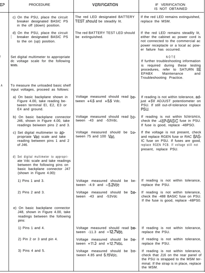
Table 4.60 Power-Up/Output Voltage Test
YiEP PROCEDtJRE
f not previously done, extract each ‘CB in the system from its
respec-ive backplane connector in basic m d LTU shelves.
Check that all circuit breakers on the ‘SU are in the off positions and that 311 fuses are inserted in their cor-,esponding locations.
Jsing the digital multimeter (or an 3c polarity indicator), verify that the :ommercial ac power receptacle Jsed for powering the systsm has the Iroper polarity.
Connect the ac power cord(s) to the zommercial ac power receptacle(s). ?lace the following circuit breakers on the PSU to the on (up) position:
a) Basic PS b) -48PSO
c) -48PSl (if equipped) d) LTUPSO (if equipped) e) L T U P S l (if equipped)
9
LTUPS2 (if equipped)If the optional MSM module is equipped in the system, proceed 2s
follows:
2) If not previously done, connect and insert battery pack into the MSM assembly. b)Press the BATTERY TEST
switch on the PSU and release after verification has been obtained.
VERIFICATION
‘olarity indication must coincide with =igures 3.00 and 3.01.
The associated green LED should light steadily.
IF VERIFICATION IS NOT 08TAlNED
if polarity indication does not coin-cide, correct before proceeding with the remainder of test in this lable.
If the green LED remains cxtin-guished, the battery pack is below acceptable voltage limits. Let MSM charge battery pack and retry test af-ter 30 minutes have elapsed. If green LED remains extinguished, the bat-tery pack is defective and requires replacement.
SATURN IlE EPABX Installation Test Procedures
A30808-X5130-8120-1-8928 issue 1, May 1986
Table 4.00 Power-Up/Output Voltage
Test (Continued)
SE?
PROCEDURE VEfiIFICATION IF VERIFICATIONIS NOT OBTAINED c) On the PSU, place the circuit The red LED designated BATTERY If the red LED remains extinguished,
breaker designated BASIC PS TEST.should be steadily lit. replace the MSM. in the off (down) position.
The red BATTERY TEST LED should 1
d) On the PSU, place the circuit If the red LED remains steadily lit, breaker designated BASIC PS be extinguished. either the cabinet ac power cord is
to the on (up) position. not connected to the commercial ac
power receptacle or a local ac pow-er failure has occurred.
7 Set digital multimeter to appropriate N O T E
dc voltage scale for the following If further troubleshooting information
tests. is required during these testing
procedures, refer to SATURN IIE EPABX Maintenance and Troubleshooting Practice.
8 A To measure the unloaded basic shelf input voltages, proceed as follows:
a) On basic backplane shown in Voltage measured should read b e - If reading is not within tolerance, a d -Figure 4.00, take reading be- tween +4.5 and +5.5 Vdc. just +5V ADJUST potentiometer on tween terminal El, E2, E3 or PSU. If still out-of-tolerance replace
E4 and ground. PSU.
b) On basic backplane connector Voltage measured should read b o - If reading is not within to!erance, J46, shown in Figure 4.00, take tween -43 and -53Vdc. check the -48P-BASIC fuse in PSU. readings beiween pins 2 and 3. If fuse is good, replace -48PSO. c) Set digital multimeter to a p - Voltage measured should be b e - If the voltage is not present, check
propriate Vat scale and take tween 75 and 100 Vat. and replace RGEN fuse or RAC
BAS-reading between pins 1 and 2 IC fuse on PSU. If fuses are good,
of J46. r e p l a c e R G E N P C B . I f v o l t a g e s t i l l n o t present, replace PSU.
d ) S e t d i g i t a l m u l t i m e t e r t o a p p r o p r i -ate Vdc scale and take readings between the following pins on basic backplane connector J47 (shown in Figure 4.00): 1) Pins 1 and 3.
2) Pins 2 and 3.
Voltage measured should be be- If reading is not within tolerance, tween -4.9 and -5.2Vdc replace the PSU.
Voltage measured should be b e - If reading is not within tolerance, tween -43 and -53Vdc check the -488 BASIC fuse on PSU. If the fuse is good, replace -48PS0. e) On basic backplane connector
J48, shown in Figure 4.00, take readings between the following pins:
1) Pins 1 and 4.
2) Pin 2 or 3 and pin 4.
3) Pins 4 and 5.
Voltage measured should read b e - If reading is not within tolerance, tween -11.3 and -12.7Vdc. replace the PSU.
Voltage measured should be b e - If reading is not within tolerance, tween +11.3 and +12.7Vdc. replace the PSU.
I
-SATURN IIE EPABX Installation Test Procedures
A3G808-X5130-B120-1-B928 Issue 1, May 1986
lbb!c 4.00 Power-Up/Output Voltage Test (Continued)
S T E P FROCEDUEE V E R I F I C A T I O N IF VERIFICATION
IS NOT OBTAINED . f) Connect positive lead of digital Voltage measured should read + If reading is not 0.05 Vdc, adjust +5V
multimeter to pin 5 of connec- 0.05Vdc. ADJUST potentiometer on PSU. If tor J48 and negative lead to adjustment is not effective, replace
terminal El on basic back- PSU.
plane. (Refer to Figure 4.00.) 813 After satisfactorily completing step
8A, proceed as follows to measure the loaded basic shelf input voltages.
a) On the PSU, place the circuit The MSM red LED designated BAT-breaker designa?ed BASIC PS TERY TEST should be steadily lit. in the off (down) position.
b) Plug all previously extracted PCBs on the basic shelf into their respective backplane connectors.
c) On the PSU, place the circuit The MSM red LED designated BAT-breaker designated BASIC PS TERY TEST should be extinguished. in the on (up) position.
d) Repeat measuring procedures Same verification as in steps 8A a) on basic backplane connectors through e), except that -t-S!/& at ter-J46, J47, J48 and terminals minal El should read between 4.85 El-E4 as indicated in step 8A. and 5.15Vdc under load.
9A To measure the unloaded LTU shelf i n p u t v o l t a g e s ( i f a p p l i c a b l e ) , p r o c e e d as follows:
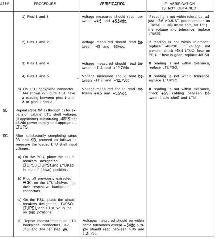
a) On the LTU backplane con-nector J42,shown in Figure 4.01,take a reading between the following pins:
1) Pins 1 and 3. Voltage measured should be b e - If reading is not within to!e:ance, a d -tween +4.5 and +5.5Vdc. just +5V ADJUST potentiometer on LTUPS. If the adjustment does not bring voltage into tolerance,replace L T U P S .
2) Pins 3 and 5.
3) Pins 3 and 4.
Voltages measured should be be- If reading is not within tolerance, tween -4.9 and -5.2Vdc. replace appropriate LTUPS. Voltage measured should be b e - If reading does not coincide with tween -43 and -53Vdc. verification reading, check the -48P LTU fuse on PSU. If fuse is good, replace -48PS0.
4) Set digital multimeter to read Vat and connect be-tween pins 2 and 3.
V o l t a g e m e a s u r e d s h o u l d b e b e - I f v o l t a g e i s n o t p r e s e n t , tween 75 and 1OOVac. check/replace RGEN fuse or RAC LTUO fuse on PSU. If fuses are good, replace PSU.
b) Set digital multimeter to ap-propriate Vdc scale.
C) On LTU backplane connector J43,shown in Figure 4.01, take a reading between the follow-ing pins:
SATURN IIE EPABX Installation Test Procedures
A30808-X5130-B120-l-6928 Issue 1, May 1986
Table 4.00 Power-Up/Output Voliagc? Test (Continued)
S T E P PROCEDURE VEFllFlCATlON IF VERIFICATION
IS NOT OBTAINED 1) Pins 1 and 3. Voltage measured should read b e - If reading is not within tolerance, a d
-tween +4.5 and +5.5Vdc. just +5V ADJUST potentiometer on L T U P S O . I f a d j u s t m e n t d o e s n o t b r i n g the voltage into tolerance, replace L T U P S O .
2) Pins 1 and 2. Voltage measured should read b e - If reading is not within tolerance, tween -43 and -53Vdc. replace -48PS0. If voltage not present, check -488 LTUO fuse on PSU. If fuse is good, replace 48PS0. 3) Pins 1 and 4. Voltage measured should read b e - If reading is not within tolerance,
tween +11.3 and +12,7Vdc. replace LTUPSO.
4) Pins 1 and 5. Voltage measured should read b e - If reading is not within tolerance, -. ttieen -11.3 and -12.7Vdc. replace LTUPSO.
d) On LTU backplane connector Voltage measured should read b e - If reading is not within tolerance, J44 shown in Figure 4.01, take tween +4.5 and +55Vdc. check +5V cabling between b e
-a re-ading between pins 1 -and tween basic shelf and LTU
2 or pins 1 and 3.
9 8 Repeat steps 9A a) through d) for ex-pansion cabinet LTU shelf voltages (if applicable) substituting -48PSl for 48Vdc power supply and appropriate
LTUPS.
9 C After satisfactorily completing steps 9A and 96, proceed 2s follows to measure the loaded LTU shelf input voltages:
a) On the PSU, place the circuit breakers designated
LTUPSO,LTUPSl,and LTUPS2 in the off (down) positions. b) Plug all previously extracted
PCBs on the LTU shelves into their respective backplane connectors.
c) On the PSU, place the circuit breakers designated LTUPSO, L T U P S l , and LTUPS2 in the on (up) positions.
d) Repeat measurements on LTU Voltages measured should be within backplane connectors J42, same tolerances except +5Vdc sup-J43, and J44 per step 9A. ply should read between 4.85 and
5 . 1 5 V d c .
I
SATURN IIE EPABX lnstallatlon Test Proccdurcs
A30808-X5130-8120-1-8928 Issue I, May 1986
J46/P46
J47/P47
SATURN IIE EPABX A30808-X5130-8120-1-8928
nstallation Test Procedures Issue 1, May 1986
i
---I
I
:42/?42
J43/P43
J44lP44
SATURN IIE EPABX A30808-X5130-B120-l-8928
Installation Test Procedures Issue 1, May 1986
5 . 0 1 General. The SATURN IIE EPABX is a Stored-Program-Controlled (SPC) system. The system is shipped with two iden-tical floppy disks that contain the basic operating and the installation-dependent data. The operating program uses the installation-dependent data, commonly referred to as the sys-tem data base, to complete and process calls as required by the customer. This information includes such items as the number of station lines and trunks in the system, as well as their operating characteristics.
The exact equipment configuration of the SATURN IIE Sys-tem must be defined in the data base in order for the sysSys-tem to operate properly. Depending on how the system is ordered, the data base is supplied in a standard format or, on request, c a n b e s u p p l i e d c o m p l e t e l y d e f i n e d a n d p r e p a r e d b y S i e m e n s . When the standard data base format is supplied, via the SATURN EPABX Data Base Preparation practice, the equip-ment configuration of the particular installation-site must be evaluated to determine if additional information must be ad-ded to the floppy disks. The floppy disks are updated via a service terminal. The procedures for defining the data base and inputting the data to memory are described in the SATURN EPABX Data Base Preparation practice and SATURN EPABX Customer Memory Update (CMU) Proce-dures practice.
5 . 0 2 b o a d j n g Operating D&a. After satisfactoriiy complet-ing the Power-Up/Output Voltage Tests in Section 4.00, the
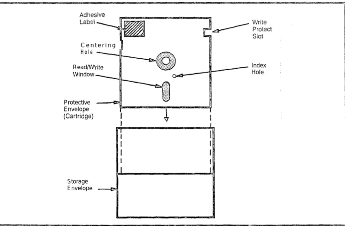
system’s operating program, contained on the floppy Uisks, is loaded into the FDD modules for the initial processor in-itialization. Both floppy disks are loaded, with either disk placed in either drive (FDDO or FDDI). Before proceeding with the loading procedures indicated in Table 5.00, the following precautions must be observed when handling the floppy disks. Figure 5.00 illustrates the floppy disk and storage envelope.
a . Prior to using a floppy disk, leave disk in the same en-vironment as the FDD module for at least 5 minutes. b. Do not place heavy objects on floppy disk.
c. Do not write on floppy disk.
d. Do not touch floppy disk suriace while hand!ing. Damage to FDD head may occur due to skin oil pick-ing up dirt.
e . Always return floppy dislc to storage envelope when it is not in use.
5 . 0 3 Inputting CMU Data to F!oppy Disk. After satisfac-torily loading the operating disks as indicated in Table 5.00, refer to the SATURN EPABX Data Base Preparation practice which defines the particular system’s data base, and SATURN EPABX Customer Memory Update (CMU) Prccsdures prac-tice to input the installation-dependent da?a to memory
C e n t e r i n g 1 H o l e
Read/W Window
Index Hole
Protective Envelope
I I
Storage Envelope
SATURN IIE EPABX
A3080&X5130-B120-l-8928
Installation Test Procedures
Issue 1, May 1986
WARNING
Hazardous voltages exist within the equipment cabinet. Be e&e&y careful when performing testir;g/~roobleshooting procedur-LJ with the equ&ment panel(s) removed.
Table 5.00 Loading Procedures for Operaling Disk
;TEP
PROCEDURE
VERIFICATION
!F VERIFICATION
IS NOT OBTA!NED
1
On the PSU, shown in Figure 5.01,
place the FAtLURE TRANSFER
switch in the AUTO position,
2
Insert a floppy disk into slot opening
of each FDD until it stops (Figure 5.02).
NOTE:
Either system disk may be placed in
either FDD.
3
Close FDD latch to secure floppy disk
in place.
4
Perform the following operations on
the CIOP PCB (Figure 5.03).
a) Connect service terminal to
Set CIOP DlP switches (Figure 5.03)
TTY connector on CIOP PCB
for service terminal in use per Table
(Figure 5.03).
5.01.
b) Depress the reset switch locat-
The following ihree messages should
If a failure occurs during initia!ization,
ed under the CIOP llY con-
appear on the service terminal:
the LEDs flash a binary value to
indi-nectar. Use pencil or other
cate loading error as described in
Ta-nonmetallic object to depress
1) THE SIB SIDE IS READY FOR
ble 5.02.
the switch.
U S E
Should any of the failures described
2) READY TO START BOOT
in Table 5.02 occur during processor
LOADER
initialization, remove the floppy disks
3)“* BOOT LOADER COMPLETE”’
from FDDs and insert the spare flop-
py disks into the FDDs. If no failures
After the last message, the red
cccur, the floppy disks previously
re-STO-ST3 LEDs perform a cycling se-
moved are defective. If the same
quence and the green ACTV LED re-
failure occurs, refer to ACTION
mains lit.
cOlumn in
Table 5,02
When the loading process is
com-plete, the red LEDs stop cycling and
one LED remains lit for a few
se-conds, then cycling starts again. The
green LED (ACTV) remains lit.
If no failures occur during processor
initialization, the four red LEDs display
a code indicating that processor
in-itialization has been completed and
the processor is on-line.
Concurrent-ly, the service terminal displays
soft-ware version, date base version, patch
level of disk software, site information
and the prompt ENTER PASSWORD.
If it is desired to perform CMU
proce-dures or clear the alarm stack, enter
the appropriate password. If the
proper password is entered, a
date-and-time prompt is displayed. If an
in-correct password is entered, INVALID
PASSWORD ENTERED is displayed.
SATURN IIE EPABX A30808-X5130-0120-1-8928
Installation Test Procedures lssuc 1, May 1936
Table 5.00 Loading Procedures for Operating Disk (Continued)
S T E P PROCEDURE VERlFlCATlON IF VERIFlCAT!ON
IS NOT OBTAINED ’ 5 If the operating disks that were
load-ed did not contain a Siemens-. prepared data base, refer to SATURN EPABX Data Base Preparation prac-tice to define the particular system data base, and the SATURN EPABX Customer Memory Update Proce-dures practice to input the installation-d e p e n installation-d e n t installation-d a t a t o t h e s y s t e m memory.
Table 5.01 CIOP DIP Switch Settings CAUTION:
Before removing GOP PCB to set switches, place BASIC PS circuit brea!:er on lhe PSU to the off (c?own) position. After replacement of ClOP PCB, place circuit breaker back
to the on (up) position.
SWITCH
NUMBER SWITCH ON (CLOSED) SWITCH OFF (OPZX)
1 Maintenance/ Test Normal
2 Not Used Not Used
3&4 Baud Rate (see note) Baud Rate (see no?e)
5 One Stop Bit Two Stop Bits
6 Odd Parity Even Parity
7 Parity Disabled Parity Enabled
8 Seven Bits Eight Bits
NOTE: The following are the baud rate combinations for switches 3 and 4.
SW3 SW4 BAUD RATE
OFF OFF 3 0 0
ON OFF 1 2 0 0
OFF ON 2 4 0 0
O N ON 9 6 0 0
I’
A30808-X5130-(3120-l-8928 Issue 1, May 1986
T a b l e 5 . 0 2 LED Display Values for Loading Errors HEX
CCDE
ERRCR DETECTED0
1
2 3 4 5 6 : D E F 8 9 A I3Start of self test not halted Main processor error EPROM checksum error MEM slot 0 low 64k test error 8k by 8 static RAM test error IRAM memory test error O R A M memory test error SIB side error
Global memory error Watchdog iimer error SIB serial loopback test error SIB counter timing test error Start boot process (self test done) Disk coniroller error
Drive not ready error CRC retry errcrs exceed 8 ST0 LED OFF :z OFF OFF OFF OFF OFF ON O N ON ON ON ON ON ON Notes:
I
S T 1 LED OFF OFF OFF OFF ON ON % ON O N ON %F OFF OFF OFFS T 2 LED OFF OFF ON ON OFF OFF % OFF OFF ON %F OFF ON ON
S T 3 LED OFF ON OFF ON OFF ON OFF ON OFF ON OFF ON OFF ON OFF ON ACTION _._________-________ N o t e 1 N o t e 1 Notes 1 and 3 N o i e 1 N o t e 1 N o t e 1 N o t e 1
NOieS
1 and 3 N o t e 1 N o t e 1 N o t e 1 ______-___--___-____--N o t e ‘ 1 Note 2 Note 21 . Upon failure, retry loading procedure. If failure persists, replace CIOP PC3.
2 . Upon failure, retry loading procedure using another set of floppy disks. If failure persists, chcc!i/replace disk drives and then CIOP PCB, if necessary.
3 . If reload and CIOP PCB replacement (Noie 1) is not effective, replace memory PCBs starting from sloi 0 until failure is no longer present.
I
--SATURN IIE EPABX Installation Test Procedures
A30808-X5130-6120-1-8928 Issue 1, May 1986
LATCH
O
P
E
N
\
LATCH
CLoSED \
/
/
?
25
0
WRITE
PROTECT
NOTCH
FLOPPY
/ DiSi’c
I
-SATURN IIE EPABX Installation Test Procedures
A30800-X5130-6120-l-8928 Issue 1, May 1986
LED
LED
(Red)
ST3
LED
ACTW
r
LED
Connector
Service
Terminal
‘witch
Figure 5.03 CIOP Printed Circuit Coard
SATURN IIE EPABX A30808-X5130-BlZO-l-8920
Installation Test Procedures Issue 1. May 1986
6 . 0 1 General. After satisfactorily loading the cperating disk and inputting CMU data to system memory via a service ter-minal, the operational capability of the system must be veri-fied after the necessary MDF cross-connections are performed. The SATURN IIE System software contains a group of system and apparatus (ancillary equipment) diag-nostic test routines which are accessed via the maintenance phone. Resulting visual and/or audible responses from these on-line diagnostic tests make it possible to verify correct oper-ation or
detect
and isolate system and apparatus malfunc-tions. If in doubt about a SATURN PCB or apparatus maliunctioning, craft personnel should refer to the SATURN IIE EPABX Mainionance and Troubleshooting praciice for fur-ther details. If a SATURN PCB or apparatus is proven to bedefective,
craft personnel should proceed according to the instructions contained in the MRA kit.6.02 Connecticn of Maintenance Phcne and Modem. Figures 6.00 and 6.01 provide the details for the maintenance phone and modem initial MDF cross-connections. Figure 6.00 also identifies the leads used when interfacing other main-tenance related equipment such as a power failure transfer subsystem and dry contact closures for remote minor and major alarm indications. Note that such equipment is customer-provided and craft personnel should follow the manufacturer’s instructions when installing them. To connect i h e maintenance phone and modem, the initial MDF
cross-connections aie as follows:
a .
Maintenance Phone. At the MDF connecting block on which PSU cable J13 is terminated, cross-connect the T&R leads of pair number 1 (W/BL- BL/W) to the T&R leads of the subscriber line circuit assigned for main-tenance purposes (refer to Figure 6.00 for details). Note that this subscriber line circuit must be classmarked with the Maintenance Diagnostic Test (TESTDIAG) and Apparatus Test (TSTAPP) features.b . Modem. From the system T&R connecting block that allocates system MDF cable J44 from the basic shelf, cross-connect the T&R of pair number 24 (V/BR- BR/V) to the T&R leads of the subscriber line circuit to be used for modem application (refer to Figure 6.01 for details). The subscriber line circuit to be used for modem ap-plication must be assigned to a class of service in which the Data Line Security (DATASEC) classmark has been enabled.
A f t e r t h e a b o v e i n i t i a l M D F c r o s s - c o n n e c t i o n s h a v e b e e n performed, the DTMF telephone set to be used as the maintenance phone can be connected to the modular jack designated MTCE PHONE on the PSU if equipped with a standard modular plug, or connected at the MDF to the T&R leads of the associated subscriber line cir-cuit. Note that if a permanent maintenance phone is
desrred in tho equipment, it may be installed neartho f r o n t o f t h e c a b i n e t , a n d c r o s s - c o n n e c t e d p e r F i g u r e 6 . 0 2 . 6 . 0 3 MDF Cross-Connecting Procedures. After the main- ’ tenance phone and modem connections have been complet-ed, perform the necessary MDF cross-connections according to the equipment configuration plan. The following illusira-tions are provided to assist craft personnel in the MDF cross connections of peripheral interfacing devices:
a . b . C . d . e . f . 9. h . i . i k. I . m n . 0 .
Figures 6.02 and 6.03 - Cross-Connections for rotary or pushbutton Single Line Telephone Instruments in-terfacing with SLMA-S and SLA16 PCBs, respectively. Figure 6.04 - Cross-Connections for Siemens Digital Telephone Interfacing with SLMD PCB.
Figure 6.05 - Cross-Connections for SATURN Atien-dant Console.
Figure 6.06 - Cross-Connections for Central Office (CO) and Direct Inward Dialing (DID) Trunks. Figure 6.07 - Cross-Connections for Two-Wire (Type I) E&M Tie Trunks.
Figure 6.03 - Cross-Connections for Four-l”dirc (T]pe I) E&M Tie Trunks.
Figure 6.09 - Cross-Ccnnections for T;:jo-Wire (T]pe I!) E&M Tie Trunks.
Figure 6.10 - Cross-Connections for Four Wire (Type II) E&M Tie Trunks.
Figure 6.11 - Cross-Connections for Recorded An-nouncement Equipment (DID and Tie Trunk Vacant Number Intercept, and ACD Announcement Service). Figure 6.12 - Cross-Connections for Coda Calling Equipment with or without Answerbaclc Capability. Figure 6.13 -Cross-Connections for DTMF Dial Dicta-tion Equipment.
Figures 6.14 and 6.15 - Cross-Connections for Music-on-Hold Feature via a Music Source, interfacing with a TMBA4 and an S L M A / S L A l G PCB, respectively. Figure 6.16 - Cross-Connections for Zoned Paging Equipment With Answerback Capability.
Figure 6.17 - Cross-Connections for Zoned Paging Equipment Without Answerback Capability.
Figure 6.18 - Cross-Connections for Zoned Universal Night Answer (ZUNA or UNA) Signaling Equipment,
I
.-SATURN IIE EPABX A30808-X5130-B120-l-B928
lnstallatlon Test Procedures Issue 1, May 1986
,-Syslein MDF Cable J13
C r o s s - c o n n e c t .to S L M A c i r c u i t d e s i g n a t e d f o r t h e m a i n t e n a n c e t e l e p h o n e .
1
J
PXFER (No&h,
Ooen1I
P X F E R ( N o r m a l l y C l o s e d )
Cross-connect to failure transfer relay(s) subsystem (customer-p r o v i d e d ) .
\$$!( M a > :tG TIPj o r - N C ) > R I N G ( M a j o r C o m m o n ) 0 1 4 D > FUBL TIP (Major-NO)
Dry contact closures for remoie miner and m a j o r a l a r m i n d i c a -tions (customer-p r o v i d e d ) .
Syslem Maiafcnancc Connecting Blsck
Figure 6.00 Mainienance Phone and Mainienance-Related Cross-Conneciions
System MDF Cable 144 from Basic Shelf
rSystem T&R Connecting Block
Cross-connect to SLMA circuit i designated for Modem application. !
Note: The cross-connections shown are used for the RAUP PCB.
SATURN IIE EPABX A30808-X5130-B120-1-6928
Installation Test Procedures Issue 1, May 1986
I I
SlNGLE L I N E ’ H O U S E /
TELEPHONE ! CABLING I
I
EQUIPMENT ROOM
I
Inlerfacing Connecting Block
System T&R Connecting Block
Sys:em MDF Cable J32, J34. J36. C38. JSO, J42 or J44 from the EZISIC shelf or J26, J28, J30, J32. J34. J36. J38, or J40 from tile LTU shelf
- - - -
f
-+(-Jo--- -________
[ ---I I I
I
Note: Dashed lilies represent installation-dependent cross-connections.Figure 6.02 Sing!e Line Telephone Cross-Connections Using SLMA PC5
SINGLE LINE I HOUSE
TELEPHONE i CABLING
I
EWIPMENT ROOM
\I
Interfacing Connecting Block
r S y s t e m T & R yecling B l o c k
System MDF Cable J321J33, J34/J35, J3EN37, J381J39, J401J41, J42/J43. or J441J45 from the
\
\
\
Basic shelf; or J26N27, J28N29, J3O/J31, J32/J33, J34/J35, J36/J37, J38/J39 or J4O/J41 \ from Lhe LTU shelf.
N o t e s : D a s h e d l i n e s r e p r e s e n t installation-dependent c r o s s - c o n n e c t i o n s
Figure 6.03 Single Line Telephone Cross-Connections Using SLA16 PCB
SATURN IIE EPABX Installation Test Procedures
A30808-X5130-B120-l-8928 Issue 1, May 1986
I I
I
SIEMENS DIGITAL : H O U S E ’ EQUlPMENT FiOOM
TELEPHONE ICABLING! .
I
I I
I I
1 I\ Interfacing. Connecting Block
DYAD or Jr-DYAD
Figure 6.04 Siemens Digital Te!cphone Cross-Connections Using SLMD PC9
System T&R Connecting Block
1
System MDF Cable J32, J34, J36. J38, J40. J42 : or J44 from the Basic shelf or J26, J28, J30, j J32, J34, J36, J38, or J40 from the LTU shelf
Note: Dashed lines represent installation-dependent cross-connections
SAbRN ATTENDANT
CONSOLE
H O U S E i EQUIPMENT ROOM
I CABLING
Interfacing Connecting Block
System T&R Connecting Block
System MDF Cable J32, J34. J36. J38. J40. J42 i or J44 from the Basic shelf or J25 J28, J30, ; J32, J34, J36, J38. or J40 from the LTU shelf j
Note: Dashed lines represent installation-dependent cross-connections.
I
Figure 6.05 SATURN Attendant Console Cross-Connections
SATURN IIE EPABX A30808-X5130-B120-1-6928
Installation Test Procedures Issue 1, May 1986
CENTRAL OFFICE
co QP C3D
Trunk Circuit
; T R U N K ; CUSTOMER PREMISES
I FAClLlTY : I
i
Local Telephone Company I
I Interfacing Connecting Bloc!c
System MDF Cable J32. J34, J35, J38, J40. J42 or J44 from the Basic shelf or J26, J28. J30, J32, J34. J36, J38. or J40 from the LTU shelf
L
System T&R Connecting DockNO!% Dashed lines represcnl ins!allalion-dependenr cross-CCnnEcfions
Figure G.06 63 and DID Trunk Cross-Connections
DISTANT OFFICE OR SlGNALING
EQUIPMENT
T R U N K i CUSTOMER PREMlSES
FACILITV 1
Interfacing Connecting Block
System T&R Connecting Block
ystem MDF Cable J32. J34. J36. J33. J40. J42 or 44 from the Dasic shelf or J26. J28. J30. J32, J34, 36. J38, or J40 from the LTU shelf
I
i
J39, J41. J43, or ‘3. J31, J33. 335. i f
System E&M Connecting Block
Figure 6.07 Two-Wire (Type I) E&M Trunk Cross-Connections
I
-SATURN IIE EPABX Installation Test Procedures
A30808-X5130.B120-l-8928 Issue 1, May 1986
D I S T A N T I -l-RUN!< I
OFFICE ; FACILITY 1
OR S I G N A L I N G ;
EQUIPMENT I
I I I I
CUSTOMER PREMISES
Interfacing Connecilng Block
System T&R Connecting Bloc!c
System MDF Cable J32. J34. J36, J38. J40, J42 or J44 from the Basic shelf or J26. J28, J30, J32, J34, J36, J38, or J40 from the LTU shelf
Y
L System MDF Cable J33, J35, J37, J39, J41, J43,or J45 from the Basic sheif; or J27. J29, J31, J33, J35. J37, J39 or J41 from the LTU she!f
L System E&M Connecting 6lock
A5135-1-4/W3!3 Figure 6.06 Four-Wire (Type ;) E&M Trunk Cross-Connections
DISTANT I T R U N K f
OFFICE t FACILITY :
OFI S I G N A L I N G ( I
EQUIPIMENT
I i
I t
CUSTOMER PREMISES
Interfacing Connecting Block
~System T&R Connecting B!ock
i
I
a
System MDF Cable J32, J34. J36, J38, J40, J42 or J44 from the Basic shelf: or J26. J28. J30, J32, J34, J36. J38, or J40 from the LTU shelf
Lo
S y s t e m M D F C a b l e J 3 3 , J 3 5 , or J45 from the Baw shelf; or J35, J37, J39 or J41 from theJ37. J27, L T U
J39. J41, J43, J29, J31, J33,
shelf
I L-.System E&M. Connecting Elock
Figure 6.09 Two-Wire (Type II) E&M Trunk Cross-Connections
I
--SATURN IIE EPABX A3080i3-X5130-B120-1-69.28
Installation Test Procedures Issue 1, May 1986
DISTANT O F F I C E OR SIGNALING
EQUIPMENT
I
Four-WireI
Type II E&M Trunk
o r Signaling
Circuit
-R -I!
Rl E
-S C -M
-SE
-TRUNK ;
FACiLlTY f
CUSTOMER PfiErvwzs
In:er:ach~g Conneclmg Block
System T&R Connecilng Block
r
-I 634. J3S. J30. J40. J42 or J44‘
J28.J~O.J32,~34.J3S.J33.
35, J37, J39. J41. JS3. or J45
7.J29, J31. J33,,‘35, J37, J29 System E&M Connecting Block
E!o!e: Dashed lines represent in s:al!ation-dependent crcc;-connections.
Figure 6.10 Four-Wiro (Type ii) E&M Tiunlc Cross-ConnecZions
Cable J32. J34, J36. J33. J40, J42 or J44 from the Basic shelf or J26. J28, J30, J32, J34. J36. J38. or J40 from the LTU shelf
A u d i o G output 81
SMl @
---S M 2 @- ---SZl a- ___---s z 2 a ----u Typical
Announcement Equipment
- S y s t e m M D F C a b l e J 3 3 . J 3 5 , J37, J 3 9 , J4!, J 4 3 , or J45 from the Basic shelf; or J27, J29. J31. J33.
Some ann~uncemenl machines send both Start Message (SM) and Make J 3 5 , J 3 7 , J 3 9 o r J41 f r o m t h e L T U s h e l f Busy (MB) signals over same par (EAIEB). P
S y s t e m E & M C o n n e c t i n g B l o c k
A5126-l-4,8/86 Figure 6.11 Recorded Announcement (DID and Tie Trunk Vacant Number intercept, and
AC3 Announcement Service) Cross-Connections
SATURN IIE EPABX Installation Test Procedures
A30808-X5130-B120-l-8928
Issue
1, May 198GConnecting Block
System T&R Connecting Block
No:es: Dashed lines represent installation-dependent cross-connectrons
Ei-drrecticnal connection to code calling device for both calling and an-swerback channels shown.
Maximum of one code calling equipment (with or without answerbaclc capa-bility) can be interfaced with the system.
When maintenance procedures are to be performed on code callrng equip-ment, associated trunk circuit must first be taken out-of-service. Failure to observe this will cause users accessing code calling to receive unan-swered ringback tone instead of busy tone.
System MDF Cable J32, J34,
J36, J38, J4.0, J42 or J44 from the
Basic shelf or J25, J28, J30, J32,
J34, J36, J38, or J40 from the LTU
sheif
~Il”-i-4:oIES Figure 6.12 Code Cailing (With or Without Answcrba~h) Cross-Comedons
s t e m MDF Cable J32, J34, J36, J38,
, J42 or J44 from the Basic shelf or
, J28, J30, J32, J34, J36, J38, or J40
m the LTU shelf
Notes: Dashed lines represent installation-dependent cross-connections,
Bi-directional connecction to DTMF dictation equipment shown.
Maximum of four DTMF dial dictation circuits can be interfaced with the s y s t e m .
When maintenance procedures are to be performed to a dial dictation equip-ment, the associated SLMA crrcuit must first be taken out-of-servrce. Fatlure to observe this will cause users accessing the dial dictation equipment to hunt to an out-of-service device and receive unanswered ringback tone instead of being routed to an in-service device or receiving busy tone.
SATURN IIE EPABX A30808-X5130-B120-l-8928
Installation Test Procedures Issue 1, May 1988
I n t e r f a c i n g Connectmg Block
System T&R Connecttng 61ocl(
I
(Op!lonal) System MDF Cable J32. J34. J36. .Jm. J40. J42 or J44 r
h
A---- from the Basic shelf or J26. J28, or J40 from the LTU shelf J33, J32, J34, J3G. J38. jIFigure 6.14 Music-cn-Wc!d Cross-Connections Using TMBA4 PC0
System E&M Connecting Block
L
System MDF Cable J33: J35, J37, J33. J41, J43. or J45 from the @asic shelf; or J27, J29, J31, J33, J35, J37, J39 or J41 from the LTU shelfNotes: Dashed lines represent installation-dependent cross-connections. Broadcast type connection from music source s h o w n . Two k i n d s o f m u s i c s o u r c e c a n b e c r o s s c o n n e c t e d , c o n -tinuous type and demand type. For con-tinuous mustc, the E&M leads are not used; and for demand music, the E&M leads are
EQUIPMENT ROOM
T
Interfacing Connecting Sloc!cSystem T&R Connecting Block
Figure 6.15 Music-on-Hold Cross-Connections Using SLMAiSLAl6 PCB Music Source
System MDF Cable J32, J34. J36, J36, JSO, J42 or J44 from the Basic shelf or J26, J26, J30, J32, J34, J36, J38, or J40 from the LTU shelf
T \a
- - - - - --- - ,--\ I 1 T Station Line
Circuit Within an SLMAlSLAlG PCB
Notes: Dashed lines represent installation-dependent cross-c o n n e cross-c t t o n s .
System MDF Cable connections are shown for an SLMA PCB. For SLA16 connections, refer to Ftgure 6.03.
Only continuous type music sources may be cross-connected.
A30808-X5130-0120-1-8928 issue 1, May 1986
System E&M Connecting Block
System MDF Cable J3.2, J34. J36, J36. J40, J42 or J44 from the Basic shelf or J26, J26, J30. J32, J34, J36. J36, or JSO from the LTU shelf
_ _
---mm
-Trunk Circuit
System E&M Connecting Block\
L
System MDF Cable J33. J35. J37, J39, J41, J43, or J45 from the Basic shelf; or J27, J29, J31, J33, J35, J37, J39 or J41 from the LTU shelf
A5!59-,-4,9:66 Figure 6.16 Paging With Answerback Cross-Connections
T y p i c a l Paging Equipment
A u d i o 8-I n p u t
i 0
BSYl 0
BSY2 0
PGl 0
PG2 0
Interfacing C o n n e c t i n g B l o c k (Optional)
[IO’ used’pJ
k/--j
.,,-I
rm7-i -w---1
-S y s t e m T & R c o n n e c t i n g B l o c k
System MDF Cable J32. J34. J36. J36. J40. J42 or J44 from the Basic shelf or JZG. J28. J30. J32, J34,
/ I J36. J38. or J40 from the LTU shelf
- - 1 L----I
I
7 L - - w - -I
I
L---s--J35, J37, J39. J41. J43, or or J27, J29. J31. J33. J35. LTU shelf
Figure 6.17 Paging Without Answerbock Cross-Connections
SATURN IIE EPABX
A30808-X5130-6120-1-8928
Installation Test Procedures
Issue 1, May 1986
System T+R Connecting Block
I
Interfacing
\
C o n n e c t i n g B l o c k
J40, J42 or J44 from the Basic shelf or
System MDF Cable J32, J34, J36, J38,
(Optional)
J26, J28. J30, J32, J34, J36, J38 or J40
i
UNA Signaling Device
from the LTU shelf
- - - a -
-With an
-SLMAISLAlG PC13
Notes: Dashed lines represent installation-dependent cross-connections.
System MDF Cable connections are shown for an SLMA PCS. For SLA16 connections, refer to Figure 6.03.
An AC signaling device operated by 20Hz ringing voltage must be con-nected to an SLMA circuit used for UNA. Each UNA circuit will drive up to four equivalent ringer loads. For installations requiring -48Vdc or a dry contact closure for UNA. appropriate external equipment must be used. The system will support up to four UNA signaling zones (i.e.; ZUNA); one SLMA circuit is assigned per zone.
Figure 6.18
U n i v e r s a l N i g h t A n s w e r ( U N A ) C r o s s - C o n n e c t i o n s
SATURN IIE EPAEX
Installation Test Procedures
I
-6 . 0 4 System Diagnostic Tests. After the necessary MDF cross-connections have been completed, the on-line diagnos-tic icsts and procedures are performed to verify the opera-tronal capability of the system. Note that the subsequent on-line diagnostic tests and procedures are presented in the sequence in which they should be performed under normal insiallation conditions. It is the responsibility of craft pers,on-nel to determine the sequence in which such tests and proce-dures should be performed when unusual installation conditions exist. Unless otherwise indicated, these tests can be performed with SDTs and/or DTMF SLTs.
a . Tone Generator Test. This system diagnostic test rou-tine verifies that each tone provided by the SMXTG PCS is generated properly. In addition, the test also checks the connection path(s) through the Memory Time Switch (MTS). Refer to Table 6.00 for the neces-sary procedures to perform the tone generator test. b . DTMF Receiver Test. This system diagnostic test
rou-tine verifies that a DTMF receiver circuit in a aarticu-lar DTMF PCB is operating properly. The test also checks the connection path(s) through the MTS. Refer to Table 6.02 for the necessary procedures to perform the applicable DTMF receiver circuit test(s). This test r e q u i r e s a T y p e 2 5 0 0 D T M F P u s h b u t t o n T e l e p h o n e S e t . c . Station Line Test. This apparatus diagnostic test
rou-tine verifies that the supervisory and transmission capabilities between an SLMA, SLA16 or SLMD cir-cuit and asscciated staiion or Siemens Digital Tele-phone instrument are operating properly. This test is performedfrom the station instrument under test and applies to both single line telephones (rotary or push-button) and Siemens Digital Telephones. Refer to Ta-ble 6.03 for the necessary procedures to perform the applicable station line test(s).
d . DTMF Pad Test. This apparatus diagnostic test routine verifies that the DTMF keypad performance, including the transmission capabilities, of any DTMF pushbutton-type station instrument is operating properly. The test is performed from the station instrument under test and only applies to single line telephones equipped with a D T M F k e y p a d . N o t e t h a t a S i e m e n s D i g i t a l T e l e p h o n e cannot be used for this test since data, not tones, are transmitted from the SDTs pushbutton keypad. Refer to Table 6.04 for the necessary procedures to perform the applicable DTMF pad test(s).
e . Console Test. This apparatus diagnostic test routine verifies that the data and speech highways to and from an attendant console are operating properly. The test also verifies that the console LED indicators, alphanu-meric display unit and audible alerting device are
oper-f . 9 h . i . j. A30808-X5130-5120s1-8928 Issue 1. May 1986
ating properly. The test is performed from the console under test. Refer to Table 6.05 for the necessary proce-dures to perform the applicable console tes:s. S i e m e n s D i g i t a l T e l e p h o n e B u t t o n T e s t s . T h e s e a p p a r a -tus diagnostic test routines verify that the signaling highways to and from Siemens DYAD and JR-DYAD tel-ephones are operating properly. In addition, the tests also verifv that the LEDs and the audible alertinn devices of the telephones are operating properly. The tests are performed using the DYAD and JR-DYAD tel-ephones. Refer to Tables 6.07 and 6.08 for the neces-sary procedures to perform the applicable Siemens digital telephone button tests.
Siemens Digital Telephone Display Test. This appara-tus diagnostic test rouiine verifies that the signaling highways to and from the Siemens DYAD telephones are operating properly. In addition, the tests also veri-fy that the alphanumeric display unit and the audible alerting devices are operating prcperly. The tests are performed using the DYAD telephones under test. Refer to Table 6.09 for the necessary procsdurcs to per-form the Siemens digital ie!ephone display tests. Trunk Test. This system diagnostic test verifies that the supervisory and transmission capabilities of an outgo-ing (or outgooutgo-ing portion of a two-way) trunk are oper-ating properly. In addiiion, the test also verifies the connec?ion p a t h ( s ) t h r o u g h t h e M T S . R e f e r t o Tab!o 6 . 1 1 for the necessary procedures to perform the epplica-ble trunk tests.
Placing Circuit(s) In-Service. This system procedure al-lows craft personnel to place an assigned circuit in service from an out-of-service state. This procedure works in parallel with the CMU procedure that changes a circuit’s state. Refer to Table 6.12 for the necessary procedures to perform the applicable in-service place-ment of circuits.
Placing Circuit(s) Out-of-Service. This system proce-dure allows craft personnel to place an assigned cir-cuit out-of service from an in-service state. This procedure works in parallel with the CMU procedure that changes a circuit’s state. Fiefer to Table 6.13 for the necessary procedures to perform the applicable out-of-service placement of circuits.
WARNING
Hazardous voltages exist Mhin the equipmcnr cebkc?. B e e x t r e m e l y c a r e f u l w h e n p e r f o r m i n g t e s t -i n g / t r o u b l e s h o o t -i n g p r o c e d u r e s w -i -i h Ehe e q u -i p m e n t panel(s) removed.