1 | P a g e
Effects of Layer-Interface Properties on Mechanical Performance of
Concrete Elements Produced by Extrusion-Based 3D-Printing
Venkatesh Naidu NERELLA, Simone HEMPEL, Viktor MECHTCHERINE*
Technische Universität Dresden, Institute of Construction Materials, 01062 Dresden, Germany
* corresponding author, tel.: +49 351 463 35920, fax: +49 351463 37268, e-mail: [email protected]
Abstract
Interfaces between layers in 3D-printed elements produced by extrusion-based material deposition were investigated on both macro- and micro-scales. On the macro-scale, compression and bend tests were performed on two 3D-printable cement-based compositions (3PCs), namely C1 and C2. The influences of binder composition and time interval between layers on layer-interface strength were critically analyzed. In the context of additive manufacturing, the optimized composition C2, containing pozzolanic additives, exhibited mechanical performance superior to that of the mixture with Portland cement as the sole binder. In particular, Mixture C2 showed a less pronounced decrease in interface tensile strength. Even for time intervals between depositions of two layers as long as 1 day the loss in corresponding flexural strength was below 25%, as compared with C2 specimens tested in the perpendicular direction. In contrast, the decrease in flexural strength measured for C1 specimens amounted to over 90% for the same set of parameters. Higher porosity at the interfaces of the printed concrete layers was identified as the cause for the lower interface strengths of C1. Microscopic observations supported the findings of the macroscopic investigations. While a pronounced recovery (“self-healing”) of the porous, discontinuous interlayers was observed with increasing age for Mixture C2, in case of C1 the filling products grown in the porous interlayer were found to be non-strengthening.
Highlights:
1. Mechanical tests and SEM investigations on layer-interface bonds were performed. 2. Composition, followed by printing interval, influenced bond strength pronouncedly. 3. Flexural and compressive strengths varied depending on the interface microstructure. 4. Microstructure inspections revealed air cavities and other defects at interfaces. 5. Mixture with SCMs yielded superior bond strengths and self-healing ability.
Keywords: Digital construction, concrete, 3D-printing, extrusion-based deposition, layer interfaces, bond strength,
cold joints, concrete testing
1. Introduction
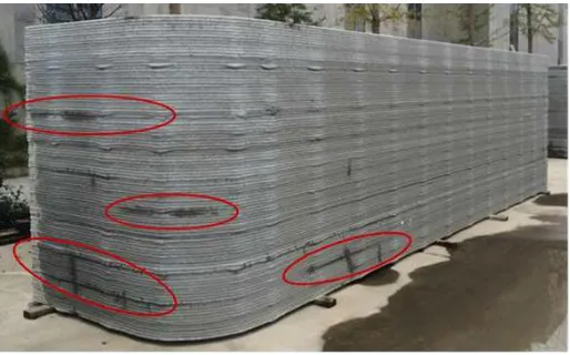
Digital concrete construction (DC) in general and 3D-printing in particular make speedy, economic, formwork-free construction possible and enable flexible architectural design with higher construction safety [1], [2]. Although 3D-printing techniques with concrete have great potential, many technological issues are still open and need to be investigated scientifically. Weak interface strengths or the occurrence of so-called “cold joints” between printed layers is one such issue. Due to the inherent “layered” nature of 3D-printed elements, layer-to-layer interfaces are unavoidable. In many instances they are the weakest links in the entire structure; see Figure 1. The weakest links induce a pronounced anisotropy and negatively affect not only mechanical performance, but also the durability of 3D-printed elements [3].
layer-to-layer interfaces in physio-chemical terms is difficult. Earlier researchers [5], [6] and design codes such as Eurocode2 [7], CEB-FIP Model code 1990 [8] designated following parameters as decisive for interface bond strengths: (a) roughness of the substrate, (b) cohesion and friction coefficients of the interface, (c) moisture content and saturation level of the substrate, (d) porosity of the substrate, (e) ambient and substrate temperatures, (f) stress normal to the interface, (g) composition of overlay concrete, especially the usage of bonding agent, (h) substrate age, and (i) if any, degree and orientation of reinforcement, i.e., connecting substrate and overlay. In hardened elements, weak joints can form due to the deteriorated or unhealthy [9] surface of the substrate, inadequate roughness of the substrate as well as lack of a cohesive chemical bond between overlay and substrate. In case of both “neighboring” layers being in a plastic state or one being in a plastic state and another quasi-plastic, the common case in extrusion-based 3D-printing, the rheological properties [10] of both “substrate” and “overlay”, significantly influence the interface properties. The static yield stress of cement-based materials at rest (upon casting or after layer depositions) increases linearly up to a characteristic fresh concrete age, usually 45 to 65 min, and increases further exponentially [11], [12]. The mechanical performance of layer-to-layer interfaces, especially under tension and shear, depends on the rheological and morphological properties as well as the physical and chemical states of both the substrate and the “overlay”. Various techniques were applied in conventional distinct layer castings, e.g. in renovation work to enhance concrete-to-concrete bonding. The approaches of sand blasting and water jetting, in general, are regarded as the most effective surface preparation techniques in enhancing bond strength [9], [13]–[17]. Other techniques include pre-wetting the substrate and treating it with chemicals. In fresh-in-fresh casting with a time interval (TI) between the layers, vibration is used to increase the flowability of concrete temporarily and to enable physical intermixing of concrete layers.
Figure 1: Signs of pronounced local water-intake (highlighted) at the layer interfaces, presumably due to high porosity of the interlayer, photo by V. Mechtcherine
In the case of extrusion-based 3D-printing, external vibration of layers already deposited is extremely risky, since it would disrupt their structural buildup and thus compromise buildability. Applying such methods as sand-blasting is not trivial, but even if technically possible they would unlikely be economical, taking the high number of layers into account. Water treatment seems to be very practicable; however, it must be controlled very precisely in order not to influence buildability and other fresh-state properties. At present there is ongoing research on other measures to improve the bond-strength of printed layers, e.g. by applying a low-viscous mineral-based primer before deposition of each subsequent layer [18]. Such approaches are not detailed here since they are out of the scope of the work at hand.
[21]–[26]. Le et al. [22] reported that average tensile bond strength was 2.3 MPa for specimens produced within time intervals (TI) of 0 min and 15 min, but only 0.7 MPa for specimens produced with TI of seven days. Zareiyan et al. [25] studied the influence of aggregate size and process parameters on interlayer adhesion. Relying on prism-splitting tests, they concluded that “bond strength for 1 inch layer fabrication with 6 min TI between layers decreased by 19% to 36% in comparison with monolithic specimens.” The interlayer bond of 3D-printed elements has also been reported for geopolymers [23]. Panda et al. [24] studied the influence of process parameters on bond tensile strength and concluded that decreasing the depositing height, referred to in [24] as nozzle standoff distance, enhanced bond strength significantly. Sanjayan et al. [26] identified the moisture content of the inter-layer region as one of the “major factors affecting the inter-layer strength”; higher moisture level on the “substrate” surface led to greater bond strength despite the longer time intervals [26]. However, there are conflicting recommendations by various published standards and technical committee recommendations on the influence of moisture/water on interface-bond-strength [14], [17].
There is, however, no standard approach to test the interface strength of 3D-printed concrete layers. So far, various studies have followed different methods. For example, Le et al. [22] printed elements with multiple, side-by-side printed layers of circular cross-section, i.e., with designed voids between the layers. The specimen production setup used by Sanjayan et al. [26] consisted of a simple piston-cylinder extruder (similar to a commercial silicone gun), which was manually filled and operated. Zareiyan et al. [25] produced specimens layer-by-layer by casting in a mold, a process which mimicked layer deposition of 3D-printing, but not completely. Each of the abovementioned approaches has its own advantages and limitations. The findings of one study may not be transferable to others due to the differences in printing processes and test procedures. This makes it necessary at this stage to characterize every 3PC separately to ensure reliable DC systematically. The intention of the authors is not to discredit any of the approaches followed, but rather to emphasize that the observed influences will differ greatly depending on the research approach chosen. The general variables are production approach, shear history due to the particular extruder geometry, type of test for interface strength, specimen size, loading direction, etc. The relatively simple approaches [25], [26] can be useful in selecting optimum mixtures from extensive mixture groups if multiple parameters are under investigation.
To the best of authors’ knowledge, no dedicated study on the influence of binder composition on mechanical performance of 3D-printed concretes has been reported. The use of secondary cementitious materials (SCM) has been proven to be beneficial for DC applications, thanks to enhancement of material thixotropy, among other parameters [4], [12], [20], [22]. At the same time, due to lack of large aggregates and the demand for rapid initial strength development, mixtures with higher dosages of cement are also commonly used in DC. Higher cement content increases the risk of shrinkage cracking, thermal stresses, weak joints [27] and a negative environmental footprint. A one-to-one comparison of mixtures with high cement clinker content as the dominant binder on the one hand and SCM with low cement clinker dosage on the other is of high research significance.
2. Materials and methods of investigation
2.1. Compositions, time intervals and specimen production
Two printable, fine-grained concrete compositions, Mixtures C1 and C2 were investigated. Mixture C1 had Portland cement (PC) as the sole binder, while Mixture C2 was given a binder consisting of 55 wt.% PC, 30 wt.% fly ash (FA) and 15 wt.% micro-silica (added as 30 wt.% of micro-silica suspension, MSS). A water-to-cement ratio w/c of Mixture C1 and equivalent water-to-binder ratio (w/c)eq of Mixture C2 were
0.42. Table 1 gives further details of the respective compositions. C1 with 627 kg/m3 cement needed a lower SP dosage than did C2, which had 391 kg/m3 of cement. In addition, the paste volume of C1 was reduced to mitigate plastic shrinkage and thermal stresses, both of which are to some extent higher in the case of higher cement content mixtures. A PC with rapid-hardening and high early strength properties, CEM I 52.5R according to EN 197-1 [28], and a Class F fly ash according to ASTM C618-12a [29] were used as dry binder components. Silica fume with a specific surface of 15-30 m2/g and a mean particle size of 0.15 µm was added as a 50 mass% aqueous suspension; 80 wt% of primary particles had diameters less than 5 µm. The choice of cement made it possible to attain the high early strength necessary for formwork-free DC. The secondary cementitious materials used in the case of Mixture C2 serve to some extent as “rheology modifiers” and “shrinkage reducers”. Two superplasticizers (SP) were used; both were polycarboxylate-based aqueous solutions and were developed for ready-mix concrete. The PCE1 was used for Mixture C1 and PCE2 was used for Mixture C2. The dosages of SP in terms of percentage by weight of binder (% bwob) are presented in Table 1. Furthermore, a very fine quartz sand (fraction 1: 0.06 to 0.2 mm) and two fine natural river sands (fraction 2: 0 to 1 mm and fraction 3: 0 to 2 mm) were used as aggregates. The sand fractions were added in the ratios of 0.2:0.2:0.6 for fractions 1, 2 and 3, respectively. Their particle size distributions can be found in [30].
Table 1: Mixture compositions under investigation
Mixture Binder (w/c)eq Paste SP SP dosage Binder content
vol. (%) %bwob kg/m3
C1 CEM 0.42 47.3 PCE1 0.75 627
C2 CEM; MSS; FA 0.42 52.5 PCE2 2.0 391; 213; 106.5
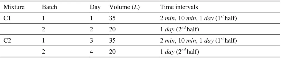
Three different time-intervals between depositions of 3D-printed layers – 2 min, 10 min and 1 day – were investigated. The TI of 2 min was the minimum time needed for the 3D-printer to produce one layer, and the TI of 10 min represents a typical TI, which is expected to be a common case for the production of full-scale wall structures. Finally, the TI of 1 day, i.e., 24 hours, represents an interruption of the building process and later resumption. To cover this case, two separate concrete batches, Batches 1 and 2, were necessary to produce the specimens; see Table 2. On the first day, specimens for 2 min and 10 min and bottom (first) half of the 1 day TI specimens were produced. The top half of 1 day TI specimens were produced on the second day. A single-shaft pan mixer CEM 60 S Elba with a maximum concrete mixing capacity of 60 L was used, following the mixing regime presented in Figure 2.
Table 2: Production batches of concrete specimens with various TI
Mixture Batch Day Volume (L) Time intervals
C1 1 1 35 2 min, 10 min, 1 day (1st half)
2 2 20 1 day (2nd half)
C2 1 3 35 2 min, 10 min, 1 day (1st half)
Figure 2: Mixing procedure
2.2. 3D-printing and mechanical testing
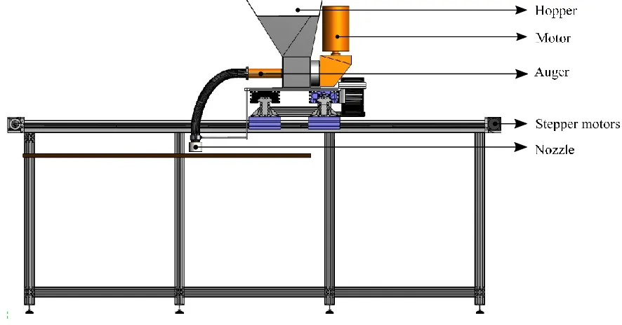
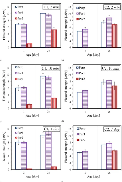
On the macroscopic scale, flexural (3-point-bending) tests and compression tests were conducted at concrete ages of 1 day and 28 days. Workability of fresh concrete was characterized using the Hägermann Flow Table test (HFT) in accordance with DIN EN 1015-3 [31]. Specimens for testing mechanical properties were 3D-printed using the 3D-concrete-printing test device 3DPTD [4]; see Figure 3.
Figure 3: Illustration of 3d-concrete printing test device and (inset) horizontal concrete deposition through a nozzle.
custom-developed control software. Both the printhead motion and concrete pump discharge rate are coupled, and the synchronization is steered with help of two parameters viz. proportionality and correction/offset [30]. The nozzle used is made of polyoxymethylene and has dimensions of 30 mm x 18.72 mm; see Figure 3.
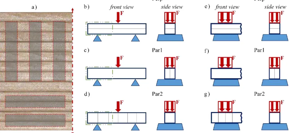
Mechanical tests were carried out on specimens which were saw-cut from a printed straight wall; see Figure 4. For this purpose, nine walls were 3D-printed with a printhead velocity of 75 mm/s. All processing parameters were kept constant, but TI between placing a subsequent layer was systematically varied; see Figure 5. Specimens were tested in three different cases: a) loading perpendicular, abbreviation Perp, to layer-interface plane, b) loading parallel to the interface plane, Par1, where in this case the specimen has just one interface plane, and c) loading is parallel to interfaces and many interfaces exist in the specimen, Par2; see Figure 4. Compressive and flexural strengths were measured according to EN 1015-11 [31]. However, the dimensions of the saw-cut prism specimens were 120 mm x 25 mm x 25 mm, deviating from the recommended 160 mm x 40 mm x 40 mm in [31]. The span of specimens for the flexural tests was 100 mm. Compression tests were conducted on the prism-halves resulted from specimens tested in the flexural tests.
It should be noted that it is possible to produce specimens of abovementioned geometry with just two layers and use them then for interface flexural tests in the directions Perp and Par1. However, preliminary investigations showed that two-layer, 3D-printed walls go through high plastic shrinkage, thus leading to cracking, a phenomenon explained by the high surface-to-volume ratio. Hence, a minimum of four layers were printed for all walls. The additional layers exert a vertical load on the investigated specimen in its fresh state as well, thus increasing the “representativeness” of the experiment in respect of large-scale applications. For specimens to be tested in Par2, eight-layer walls were produced; see Figure 4. All the printed walls were protected from surrounding influences by covering with wet textile and a polythene sheet until 24 h after printing. From an age of 1 day printed walls were cured under water for 7 days and in climate-controlled chamber from the 8th day to the 28th day.
Figure 4: a) Representation of specimen extraction from printed concrete wall, b-d) flexural test setups and e-g)
compression test setups. The blue lines inside the specimens indicate layer-interfaces. The dashed green insets indicate prism halves used for compression tests.
2.3. Optimized printing sequence
also influence the interface properties. If walls for each TI were to be produced sequentially, i.e. printing layers of a second wall only after fully completing printing the first wall, then the total production time would exceed many hours. Similarly, if all the layers of a wall were to be printed with a specified TI, e.g. 1 day, then a total of 8 day and 8 batches of concrete would be needed for producing walls with TI of 1 day. Considering these challenges, the specimen production regime was optimized in such a way that the “waiting time” between various layer depositions of a particular wall was used to produce layers for another wall. Only one layer interface (central) in the walls was produced with the specified TI, while all other interfaces were produced with as short a TI as possible. For instance, in the wall 3 of 1 day TI only the fifth layer was produced with 1 day TI and all other layers were produced with 2 min TI; see Figure 5. The optimized production sequence for all the 3D-printed walls is presented in Figure 5. Wall numbers are denoted following the printing sequence as W1, W2...W9. Figure 5 also gives the total number of layers in each of the walls, corresponding TI and age of concrete from the time after water addition at the beginning of each layer. The nomenclature for the various cases investigated in this study is detailed in Figure 6.
Figure 5: Layer-deposition schema (not scaled): Top and front view of the printed walls (L= length, H= height) are
depicted with the age of concrete at the beginning of each layer shown; also the time intervals and number of layers as well as printing sequence are presented.
2.4. Microscopy
The region between two layers was investigated by means of SEM (QUANTA 250 FEG, FEI) in low vacuum mode. In addition, the microstructure at a reference point in the core of a layer was captured and compared with the microstructure of the interface of two printed layers; see Figure 7a. The samples were examined in the natural state without application of conductive layers. The cross-sections of printed specimens prepared through sawing does not represent the interface clearly due to the influence by pseudo-polishing by the saw blades. Hence, the specimens were prepared by splitting. Splitting force was applied vertically to the printing direction to get a “fresh” broken surface; see Figure 7. Though splitting is expected to exert lower mechanical stresses than wet-grinding, the microscopic investigations showed that the splitting process led in some cases, where bonding between the layers was weak, to opening or cracking along the interface.
Figure 7: a) Regions investigated under microscope: reference and interface, b) saw-cut surface, c) split surface and
d) typical specimen on the platform of SEM
3. Investigations on the macroscale: results and discussion
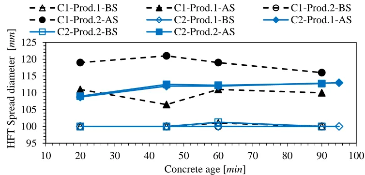
3.1. Evaluation of fresh concrete propertiesThe rheological properties of concrete in fresh state have significant influence on the layer-interface properties [10], [21]. With respect to the Bingham parameters – yield stress and plastic viscosity – the yield-stress is expected to be more significant in the case of non-vibrated, layer-wise concrete deposition. This can be substantiated by noting that there is no mechanical intermixing, i.e. with resulting higher shear rates occurring between two deposited layers, as in the case of distinct layer casting [10]. In contrast, the flowability under self-weight (flow initiation) plays a more significant role. Hägermann Flow Table (HFT) spread values for both C1 and C2 measured from various batches are presented in Figure 8. They correlate with the yield stress of concrete and thus give an indication of the investigated concretes rheological states at the time of production.
Figure 8: HFT spread diameters of concretes C1 and C2 after and before strokes from production batches 1 and 2.
95 100 105 110 115 120 125
10 20 30 40 50 60 70 80 90 100
HFT
Sp
read d
iam
eter
[
mm
]
Concrete age [min]
C1-Prod.1-BS C1-Prod.1-AS C1-Prod.2-BS
C1-Prod.2-AS C2-Prod.1-BS C2-Prod.1-AS
All tested mixtures had a HFT spread value of 100 mm, equal to base diameter of the frustum before strokes, and values under 120 mm after applying 15 strokes [32]. Such a very low spread is a prerequisite to achieve buildability of 3PCs if no accelerator is dosed in the nozzle. The HFT spread values after strokes of C2 for both batches and the C1 first batch as well were almost identical. The HFT spread after strokes of the C1 second batch (1 day TI) was slightly higher than that of the C1 first batch and, importantly, greater than that for both batches of C2. This means, from a pure “flowability” point of view 1-day TI specimens of C1 are more likely to develop a good interface bond than those of C2. Nevertheless, the mechanical properties testing indicates that C2 has a superior bond to that of C1; see the following sections. Thus, we can conclude that the better interface bond in the case of C2 did not originate primarily from its rheological properties, in terms of higher flowability, but rather from its material composition and the physio-chemical aspects of the layer-interface.
3.2. Interface properties and flexural strength
Bending test results, which are most relevant for evaluation of the bond strength, are summarized in Table 4 and graphically illustrated in Figure 9. The overall flexural strength of Mixture C1, i.e., the mean of all directions and time intervals tested, at the age of 28 day is 7.67 MPa with coefficient of variation of 42.6%. The same for Mixture C2 is 7.39 MPa, with a coefficient of variation of 10.5%. The very high coefficient of variation for C1 is explained by the influence of the layer interface on the flexural strengths detailed above. In Perp and Par1 directions the flexural strengths of the ‘cement only’ composition — C1, are clearly higher than composition C2 at both the ages tested. However, in the critical direction of Par2 the flexural strengths of C1 are significantly lower than that of C2, clearly substantiating the weak interface bond of C1. The strength loss in terms of flexural strength, ∆flex, due to layered manufacturing is given as
the ratio of difference in flexural strength from ‘Perp’ and ‘Par2’ tests to the flexural strength in ‘Perp’ direction:
∆
𝑓𝑙𝑒𝑥=
𝑓𝑙𝑒𝑥𝑢𝑟𝑎𝑙 𝑠𝑡𝑟𝑒𝑛𝑔𝑡ℎ 𝑃𝑒𝑟𝑝−𝑓𝑙𝑒𝑥𝑢𝑟𝑎𝑙 𝑠𝑡𝑟𝑒𝑛𝑔𝑡ℎ 𝑃𝑎𝑟2𝑓𝑙𝑒𝑥𝑢𝑟𝑎𝑙 𝑠𝑡𝑟𝑒𝑛𝑔𝑡ℎ 𝑃𝑒𝑟𝑝 (1)
It can be anticipated that flexural strength is not significantly affected by the presence of weak layer interfaces when loading is perpendicular (Perp) to the joints. In comparison to the Perp series, no negative effect on the flexural strengths was observed if the loading direction was Par1; see Figure 4 for loading cases. Considering the particular arrangement of joints in this series, this result is well plausible and could be expected. Again, as expected the specimens tested in the Par2 arrangement yielded considerably lower values of flexural strength. The tensile stresses act here perpendicular to several layers interfaces, which in failing at moderate stress levels are definitively the weak links. From the results presented in Table 4 and Figure 9, it is evident that concrete C2 has much better interface strength in comparison to concrete C1; see low values of strength loss ∆flex. This is despite Mixture C2’s lower flexural strengths in loading cases Perp
at both ages tested. For C2, flexural strengths in Par2 direction are not available for the age of 1 day due to a measurement error; however, the trend is expected to be similar as that observed for 28 days old specimens.
The weaker interface bond strength in the case of C1 in comparison to C2 can be hypothetically attributed to various aspects, including: (a) porosity and saturation state of the substrate, (b) moisture condition of the surface, (c) magnitude of plastic shrinkage, (d) varying yield stress and/or plastic viscosities of the deposited material and substrate. As detailed in Section 3.1, Mixture C1 was slightly more flowable than C2, and so the yield stress could not be the primary reason for its weaker interface properties. It was reported that higher moisture levels on the surface increase interface bond strengths, despite longer TI [26]. Visual examination carried out during the 3D-printing of the specimens indicated that Mixture C1 had higher surface moisture throughout the printing duration than the C2 specimens.
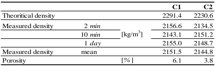
A further reflection concerns the porosity of the printed material. Mixture C1 had only Portland cement as binder while C2 had a considerable portion of pozzolana fines (FA or MSS). It is known that the addition of MSS usually leads to a denser microstructure. Additionally, lower binder volume content in C1 may cause some difference in pore structure, too. The porosity of the printed specimens is given in Table 3. In the absence of dedicated porosity measurements, it was quantified as the ratio of “difference between measured and theoretical densities” to “the theoretical density”, assuming zero % air content. The measured density is the mean value of the measured densities of specimens mechanically tested in various directions. The theoretical density was calculated as the sum of all the constituents’ “input” weights per unit volume. The porosity of the printed C1 specimens is, at 6.1 %, nearly 60 % higher than that of the C2 specimens. Microscopic and naked-eye visual examinations, in case of C1, revealed large pores/cavities both at the interface and as well as in the core of the printed specimens. Such large pores, ranging from 50 µm to over 500 µm, reduce drastically the interface contact area of two 3D-printed layers. Due to their large size, these pores can be regarded as micro-cracks. Thus, on one hand, the resulting reduction in interface bond area; on the other hand, high stress concentrations on the pore (”crack”) edges, naturally reduces the overall interface bond strength. The stress concentrations on the pore edges increase over-proportionally with increasing flaw size (fracture mechanics). Moreover, even if the pores are not on the surface (in the interface zone), but just below it, they still lead to weak lower bond strengths as this area is subjected to higher bending moment than the rest of the specimen during testing. In contrast to C1, the Mixture C2 has significantly lower number of large pores both at the interface and as well as in the core, the reasons of which were addressed above already.
Table 3: Density and porosity of 3D-printed specimens at concrete age of 28 days.
C1 C2
Theoritical density 2291.4 2230.6
Measured density 2min 2156.6 2134.5
10min 2143.1 2151.2
1day 2155.0 2148.7
Measured density 2151.5 2144.8
Porosity [%] 6.1 3.8
mean
[kg/m3]
3.3. Compressive strengths
Generally, simple compression testing is well understood as an “inappropriate” method in investigating interface strength. Shear tests, compression tests with specified notches [10] and compression tests on specimens cast so that the layer-to-layer interface plane is inclined to loading direction [32], [33], are much more suitable. Such approaches were not followed in the current research. The compressive test results are, however, still of general interest: 1) in classifying the printable cement-based composites developed, 2) for comparative selection of various mixtures, and c) for eventual utilization in structural analyses and design. Similar to the flexural strength loss, ∆flex, the compressive strength loss due to layered
manufacturing, ∆comp, is calculated as the ratio of difference in compressive strengths from ‘Perp’ and ‘Par2’
tests to the compressive strength in ‘Perp’ direction; see Eq. (2).
∆
𝑓𝑙𝑒𝑥=
𝑐𝑜𝑚𝑝𝑟𝑒𝑠𝑠𝑖𝑣𝑒 𝑠𝑡𝑟𝑒𝑛𝑔𝑡ℎ 𝑃𝑒𝑟𝑝−𝑐𝑜𝑚𝑝𝑟𝑒𝑠𝑠𝑖𝑣𝑒 𝑠𝑡𝑟𝑒𝑛𝑔𝑡ℎ 𝑃𝑎𝑟2𝑐𝑜𝑚𝑝𝑟𝑒𝑠𝑠𝑖𝑣𝑒 𝑠𝑡𝑟𝑒𝑛𝑔𝑡ℎ 𝑃𝑒𝑟𝑝 (2)
As expected, no definite quantitative conclusions could be drawn from the strength loss values calculated from compressive strength values in respect of weak joints. Remarkably, however, the coefficient of variation for 28 days compressive strength (7.8% for C1 and 2.0% for C2) follows the same trend as the coefficient of variation for flexural strength at this age (42.6% for C1 and 10.5%), i.e., Mixture C1 shows higher variation in its strength values depending on testing direction both in bending and compression, thus indicating higher anisotropy of specimens made of this mixture. Remarkable is also the much lower magnitude of variation in the case of compressive tests, which shows the less pronounced anisotropy with respect to the material performance under compressive loading. Furthermore, it is noteworthy that the “losses” in compressive strength are mostly negative, i.e. compressive strength in direction Par2 is actually higher than that measured in Perp direction; see Table 4 and Figure 11. Summarizing these observations, it can be concluded that although the simple compression tests performed in different directions cannot provide exact data on how the interface bond varies for given compositions and fabrication procedures, they seem to be able to serve well for quick estimations of anisotropy arising out of various compositions and process parameters.
The overall 28 day average compressive strength of Mixtures C1 and C2 for all directions and time intervals is 100,0 MPa and 71.8 MPa, respectively; see Table 4. Thus, both compositions can be classified as high-strength “concretes” according to EN 206 [34]. The overall 1 day average compressive strength of Mixtures C1 and C2 for all directions and time intervals is 40.5 MPa with coefficient of variation of 0.9% and 32.8 MPa with coefficient of variation of 8.7%, respectively. The compressive strength attained at 1 day is 56% and 33% of 28 days strengths for Mixtures C1 and C2, respectively. This can be explained by the comparatively higher cement content of C1 (627 kg/m3) than that of C2 (391 kg/m3); see Table 1. However, it is noteworthy that at the age of 28 day, Mixture C2 has 30% higher compressive strength than Mixture C1, ascertaining once again the benefits of using pozzolanic additives in concretes for DC. The authors refer here to the fact that use of SCMs also improves rheological behavior of printable cement-based composites by enhancing thixotropy and therewith the increase in static yield stress [12].
13 | P a g e
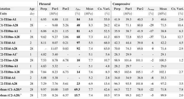
Table 4: Flexural and compressive strengths of printed specimens at ages of 1 day and 28 days.
Flexural Compressive
Notation Age Perp Par1 Par2 ∆flex Mean Co. Vari. Perp Par1 Par2 ∆comp Mean Co. Vari.
Units day [MPa] [%] [MPa] [%] [MPa] [%] [MPa] [%]
C1-TI1m-A1 1 6.93 6.88 1.11 84 5.0 55.0 41.9 39.3 40.5 3 40.6 2.6
C1-TI1m-A28 28 - 9.68 5.26 48 8.3 26.2 62.6 71.1 80.8 -29 71.5 10.4
C1-TI10m-A1 1 6.06 6.21 1.15 81 4.5 52.5 35.9 38.7 41.9 -17 38.8 6.3
C1-TI10m-A28 28 9.62 9.27 3.06 68 7.3 41.2 60.9 72.8 83.5 -37 72.4 12.7
C1-TI1d-A1 2 8.11 8.07 0.21 97 5.5 68.0 42.3 44.4 39.8 6 42.2 4.5
C1-TI1d-A28 28 - 11.07 0.83 92 7.4 63.0 70.0 74.3 69.8 0 71.4 2.9
C2-TI1m-A1* 1 4.82 5.40 - - 5.1 5.6 28.3 29.9 - - 29.1
C2-TI1m-A28 28 7.53 8.78 6.78 10 7.7 10.7 98.9 101.6 101.1 -2 100.5 1.2
C2-TI10m-A1 1 4.83 5.32 - - 5.1 4.8 28.2 29.7 - - 29.0
C2-TI10m-A28 28 7.84 8.23 6.73 14 7.6 8.3 98.5 102.6 105.1 -7 102.1 2.7
C2-TI1d-A1 2 5.08 5.38 - - 5.2 2.8 34.0 34.9 36.8 -8 35.3
C2-TI1d-A28 28 7.29 7.76 5.61 23 6.9 13.4 96.3 93.5 101.8 -6 97.2 3.5
Mean (C1-A28)* 28 9.97 10.00 3.05 69.3 7.7 42.6 64.5 72.7 78.0 -22 71.8 7.8
Mean (C2-A28) * 28 7.55 8.26 6.37 15.7 7.4 10.5 97.9 99.3 102.7 -5 99.9 2.0
14 | P a g e
One hypothesis for the observed influence is the differential water evaporation from the specimens produced with varying TI. The specific amount of water evaporated, increases with increasing surface-to-volume ratio s/v. If a single specimen is examined as two parts: substrate and overlay, the s/v of the individual parts is higher than that of the total specimen. This implies that if the substrate is exposed longer without protection from drying, the water loss will be higher. The increased water loss may have led to increased porosity and shrinkage cracks, both of which can reduce the compressive strength. Alternate explanations are explored below.
One probable reason for observed differences in compressive strength measured in different directions can be explained as follows: The specimens and the loading adapter/plane used for uniaxial compression tests in this study were not cubical and square shaped, respectively. The compressive tests were conducted on prism-halves with dimensions of 25 mm x 25 mm x 60 mm; see Figure 4. The compression load was applied on an area of 25 mm x 40 mm. Front, side and top views along with stress distribution in investigated loading cases are shown in Figure 11. The blue lines indicate layer interfaces. The specimens in compression tests typically fail along so-called shear planes which “separate” the specimen core standing under tri-axial compression from the outer regions which are under a mixed compression-tension mode. The weak interfaces are the weakest links in the specimen and can, thus, trigger crack formation. Both the extent of the (weak) interface area lying outside the tri-axial compressive core and the size of individual defects lying in the crossing of shear planes are factors decisive for the observed load level at failure. In the case of the Perp arrangement, the weak interface area outside the tri-axial compressive zone is the largest, which may explain why the strength values measured in this direction are the lowest. In the cases of Par1 und Par2 the extension of interfaces outside the tri-axial compressive region is more or less the same. The weak interfaces within this region are aligned with the acting force in both cases, however in the Par1 arrangement, a longer portion of the interface is involved when compared with the Par2 arrangement. Since the weak interfaces oriented parallel to the load may lead to splitting of the specimen and to premature failure, an on-average lower compressive strength measured for Par1 (larger weak area aligned with the loading direction) seems explicable. Remarkable in the case of 28 days compression tests on C2, i.e., the case with the strongest interface among the cases tested, the difference in compressive strengths obtained for all three directions is the least.
Figure 11: Stress distribution in loading cases investigated: a) Perp, b) Par1 and c) Par2. Units are in mm. The blue
lines and colored plane indicate layer interfaces and interface planes, respectively.
case. The likelihood of the Par2 specimens’ being denser is indeed plausible. The average densities of specimens made of both compositions in Perp, Par1 and Par2 directions are 2143 kg/m3, 2146 kg/m3 and 2156 kg/m3, respectively. This substantiates the observed compressive-strength variation’s possible origin in process-induced density variation, at least to some extent. Summarizing, it can be stated that both the presence of weak interfaces and potential variation in the compaction degree are the likely causes of the anisotropic mechanical properties as observed in compression tests on printed concrete specimens.
4. Microscopic investigations: results and discussion
4.1. General observations and classificationThe presence of weak joints in the majority of the investigated cases, especially at an early age of 1 day was evident from microscopic analysis of the specimens. Based on visual inspection the interfaces could be roughly subdivided in the following four cases: A) weakly bonded, B) weakly bonded due to process and curing conditions, C) temporarily weakly bonded and D) strongly bonded. Case A is identified when the interface exhibits long and wide separations between the two neighboring layers, where the separations are unlikely to be self-healed or bridged by hydration products before examination/testing at the age of 28 days; see Figure 12a.
Case B is associated with interfaces weakened by the entrapment of air during layer deposition or by other phenomena such as plastic or drying shrinkage and/or carbonation at the substrate, i.e., the layer deposited first, in the case of an extended time interval before deposition of the subsequent layer; see Figure 17 for the last case. Thus, by definition the occurrence of Case B could be mitigated by changing concrete composition and/or process parameters, such as TI and/or utilizing a proper curing regime. Sanjayan et al. [26] observed as well that the “moisture level at the surface between the layers is one of the major factors affecting the inter-layer strength”. Various solutions are conceivable in providing external or internal curing and, hence, mitigate the negative consequences of moisture loss as well as plastic and drying shrinkage. In providing for internal curing one of the seemingly promising examples in the absence of protecting formwork is the addition of superabsorbent polymer in printable concrete [3]. Such a measure has already proven itself efficient in reducing shrinkage-induced cracking in the use of cast concrete.
Case C represents temporarily weak interfaces, whose layer separations are narrow and less porous in comparison with Cases A and B, and which clearly indicate a self-healing tendency over time due to the formation of hydration products; see Figures 12c and 14. Case D means that both layers are bonded/interlinked tightly; actually, the interface between layers looks very similar to reference regions in the core; see Figure 12d.
a) C1-TI1d-A28: Very long, wide separation between layers.
c) C2-TI1d-A28: narrow interface filled by delayed hydration products.
d) C2-TI2-A28: zoomed pictures indicating interface (right) quality as good as that of the core region (left).
Figure 12: SEM images showing the four observed types of layer-interface microstructure.
4.2. Microstructural differences between the 3PCs C1 and C2
Weak joints were observed for Mixture C1 with respect to all TIs under investigation. In the case of the shortest TI of 2 min, the difference between interlayers in C1 and C2 specimens is very clear. Despite the shortest TI, C1-TI2-A28 probes show layer separation with horizontal separation length of over 1000 µm and vertical separations of over 200 µm;see Figure 13a. In addition to parallel separation, elliptical cavities also could be observed, which can be explained by air “enclosure” during the upper layer deposition supported by the surface unevenness of substrate and upper filament. In the case of C1, however, the air voids occur not only at the interface but also in the core of the layers, independent of the TI; see the following subsections for further explanation and Figure 12b.
a) C1-TI2-A28 b) C1-TI10-A28
Figure 13: Weak joints in C1 specimens depicting very long, wide separations between layers deposited with TI of a)
2 min and b) 10 min.
Overall, the microstructures of specimens made of C1 and C2 clearly show that for the same time interval Mixture C2 yields a more homogeneous microstructure at the layer-interfaces. In case of 1 day TI specimens, long needle-shaped ettringite crystals are found in numerous positions of the layer interface’s “empty” space; see Figure 15. At the same time, spherical clusters of ettringite are also present in narrower spaces. Additionally, delayed growth of other hydration products, especially freely hanging calcium hydroxide in larger voids could also be identified as well. As reported in [35], among others “carbonation processes, moisture effects and, with that, moisture and temperature changes such as those which occur under natural conditions can cause ettringite formation in hardened concrete”. Further investigations are needed to confirm whether the easier transport of external water and gases leads to delayed preferential growth of these products at the interfaces and in their vicinity.
4.3. Microstructural changes over time
a) C2-TI2-A1: Hydration products (mainly C-S-H phases) of both layers are touching and growing into each other.
b) C2-TI2-A28: Very tightly bonded layers more or less throughout the interface.
c) C1-TI2-A28: Very tightly bonded layers; overall area of such good bond is however limited; see d).
d) C1-TI2-A28: Investigated specimen
Figure 14: Self-healing of the interface by layer-bridging with hydration products.
a) C2-TI1d-A28: apparent almost complete filling of separation at the interface.
b) C1-TI10-A28: large separation showing free-hanging portlandite
Figure 15: Examples of a) apparent, partial self-healing and b) only partial filling of large separation with
hydration products.
4.4. Process aspects
Another distinctive feature displayed by the SEM images of 3D-printed specimens are longitudinal cavities and air voids occurring both at the interface and in the “core” of the layers; see Figure 16. They differ distinctly from usual air voids and capillary pores in concrete by their shape and size. The large air voids were found mostly in the specimens made of C1, especially in the core. The typical longitudinal cavities induced by 3D-printing originate from air entrapped between layers, the process likely depending upon the rheology of the concrete, the speed of printing, the distance between previous layer and nozzle, the shape of extrudate, and the possible vibration of the printhead. The greater number and larger size of such voids in the case of Mixture C1 can be explained by the observation that this mixture containing Portland cement as only binder had a coarser matrix and was less cohesive than Mixture C2, which contained fine micro-silica and fly ash. Furthermore, certain oscillations of the nozzle could facilitate the formation of long cavities due to entrapped air between slightly wave-like layer shapes.
Influence of printing process parameters on interface strength was also reported by Panda et al. [23]. The tensile bond strength of interface was found to be in nearly inverse-linear proportion to the deposition elevation of the new layer above the substrate: With an increase in the deposition height from 0 mm to 4 mm, the tensile bond strength decreased from 2.3 MPa to 1.5 MPa.
a) C2-TI2-A1: Cavities at the interface and in the core
b) C2-TI2-A28: cavities due to “air enclosure” at an otherwise very well bonded interface.
It is obvious that a reduction of the deposition height without altering concrete discharge rate and printhead velocity should lead to a better “compaction” of the deposited material against substrate, resulting in enhanced interface properties. The large cavities observed in the present study can be likely traced back to a considerably high deposition height of 2 cm, which was chosen in order to achieve higher dimensional accuracy. More or less as a consequence, cavities could be formed at the interfaces between printed layers depending on the rheological state of the material at the time of extrusion and the nozzle-oscillation amplitude. Though large cavities at the interface can be seen both in C1 and C2 specimens, their frequency was much lower in the case of Mixture C2. Moreover, curing conditions also exhibit a pronounced influence on specimens’ features in case of TI of 1 day. Despite the careful protection of printed specimens by wet cloths and polythene sheets from the surrounding atmosphere, 1 day TI specimens made of C2 underwent remarkable carbonation. Especially the top surface of the previous layer (produced one day earlier) showed clear formation of calcites, which prevented it from developing a complete bond with the subsequent layer; see Figure 17.
Figure 17: a) Calcite formation at the layer-interface of C2-TI28-A28, b) general view of the corresponding
specimen
5. Summary and conclusions
In the article at hand, first, the mechanical properties of 3D-printed, fine-grained concrete specimens were investigated with respect to the effect of interface quality between individual layers, accompanied by microscopic analysis, particularly of the interface areas. The 28 days overall mean compressive strength for Mixtures C1 and C2 were 100.0 MPa and 71.8 MPa, respectively. The changes in the material composition and time intervals between placements of subsequent layers exhibited a pronounced influence on the interfaces’ microstructure and, therewith, on the degrees of material heterogeneity and anisotropy. The material composition has been proven decisive in achieving a good bond between individual layers, even for long time intervals. So, Mixture C2, containing high amounts of supplementary cementitious materials, showed superior performance in terms of both homogeneity of microstructure and low dependency of mechanical properties on the direction of loading when compared to Mixture C1, made with Portland cement as its sole binder. Further conclusions can be summarized as follows:
2. Although the uniaxial compression tests cannot adequately quantify interface strength, they can – if performed in three different directions – still serve as an indicator of the specimens’ anisotropy. 3. Close examination of various potential mechanisms revealed a) higher porosity, b) higher amount of
large pores/microcracks at the interface and in the core, and possibly also c) drying and plastic shrinkage of deposited material as causes for the observed weak interface bond strengths, in particular, in the case of C1.
4. The presence of weak-interface in the majority of the 3D-printed specimens was established. Observed interfaces were classified into four categories based on their visual appearance, separation distance, and origin.
5. SEM images clearly indicated the influence of time intervals and material composition on the interfaces’ quality. The formation of large cavities at the interfaces and in the cores of C1 specimens explains its weaker interface bond.
6. For some specimens, e.g., for the series C2-TI2-A28, no weak interfaces between layers were identified. In some other specimens, interface flaws seem to be largely filled/self-healed with hydration and/or carbonation products. However, such specimens did not always yield an expected gain in flexural strength since the filling products were in some cases C-S-H phases efficiently bridging the layer-separations, while in other cases calcite, ettringite, and/or portlandite crystals, which did not exhibit any significant defect-bridging action with respect to the transfer of tensile forces.
Certainly more research is needed to be able to develop appropriate strategies for mitigating the formation of weak interlayer joints by adjusting material composition and process parameters as well as by using some additional measures such as internal or external curing and application of a low-viscosity mineral-based primer before deposition of the subsequent layer. The same holds true with respect to the prediction of properties of interfaces between extruded layers, not merely mechanical properties, but all properties related to the transport of fluids, gases and ions. To gain further insights into the layer-interface behavior, the authors are currently extending the experimental program to other investigation methods, including uniaxial tension tests and capillary suction quantification through neutron radiography. Also, the growth of self-healing/filling reaction products must be studied in more detail, including their influence on the durability of 3D-printed concrete elements.
Acknowledgments
This work is a part of V. N. Nerella’s PhD research. The authors thank Christian Stahn of the Institute of Construction Materials, TU Dresden for his support in conducting the mechanical tests.
References
[1] R. A. Buswell, R. C. Soar, A. G. F. Gibb, and A. Thorpe, “Freeform Construction: Mega-scale Rapid Manufacturing for construction,” Autom. Constr., vol. 16, no. 2, pp. 224–231, 2007.
[2] T. T. Le, S. A. Austin, S. Lim, R. a. Buswell, A. G. F. Gibb, and T. Thorpe, “Mix design and fresh properties for high-performance printing concrete,” Mater. Struct., vol. 45, no. 8, pp. 1221–1232, 2012.
[3] C. Schröfl, V. N. Nerella, and V. Mechtcherine, “Capillary Water Intake by 3D-Printed Concrete Visualised and Quantified by Neutron Radiography,” in First RILEM International Conference on Concrete and Digital Fabrication - Digital Concrete 2018, T. Wangler and R. J. Flatt, Eds. Zürich: Springer International Publishing, 2019, pp. 217–224.
[5] D. S. Santos, P. M. D. Santos, and D. Dias-da-costa, “Effect of surface preparation and bonding agent on the concrete-to-concrete interface strength,” Constr. Build. Mater., vol. 37, pp. 102–110, 2012. [6] D. Dias-da-Costa, J. Alfaiate, and E. N. B. S. Júlio, “FE modeling of the interfacial behaviour of
composite concrete members,” Constr. Build. Mater., vol. 26, no. 1, pp. 233–243, 2012.
[7] CEN, EN 1992-1-1, Eurocode 2: design of concrete structures – Part 1-1: General rules and rules for buildings. 1992.
[8] CEM-FIP: Model Code 90 – design code. Bulletin 213/214. 1993.
[9] E. N. B. S. Júlio, F. A. Branco, and V. D. Silva, “Concrete-to-concrete bond strength. Influence of the roughness of the substrate surface,” Constr. Build. Mater., vol. 18, no. 9, pp. 675–681, 2004.
[10] N. Roussel and F. Cussigh, “Distinct-layer casting of SCC: The mechanical consequences of thixotropy,” Cem. Concr. Res., vol. 38, no. 5, pp. 624–632, 2008.
[11] T. Lecompte and A. Perrot, “Non-linear modeling of yield stress increase due to SCC structural build-up at rest,” Cem. Concr. Res., vol. 92, pp. 92–97, Feb. 2017.
[12] V. N. Nerella, M. A. B. Beigh, S. Fataei, and V. Mechtcherine, “Strain-based approach for measuring structural build-up of cement pastes in the context of digital construction” Cem. Concr. Res., 2018. [Accepted]
[13] K. R. Hindo, “In-place bond testing and surface preparation of concrete,” Concr. Int., no. April, pp. 127–129, 1990.
[14] F. Saucier and M. Pigeon, “Durability of new-to-old concrete bonding,” in Proceedings of the ACI International Conference Evaluation and Rehabilitation of Concrete Structures and Innovations in Design, vol. 1, 1991, pp. 689–707.
[15] P. H. Emmons, “Concrete Repair and Maintenance Illustrated”. MA: Butterworth-Heinemann Limited, 2003.
[16] S. Austin, P. Robins, and Y. Pan, “Tensile bond testing of concrete repairs,” Mater. Struct., vol. 28, pp. 249–259, 1995.
[17] E. N. B. S. B. S. Júlio, F. A. B. B. Branco, V. D. Silva, and J. F. Lourenço, “Influence of added concrete compressive strength on adhesion to an existing concrete substrate,” Build. Environ., vol. 41, no. 12, pp. 1934–1939, 2006.
[18] T. Marchment and J. Sanjayan, “Method of Enhancing Interlayer Bond Strength in 3D Concrete Printing,” in First RILEM International Conference on Concrete and Digital Fabrication - Digital Concrete 2018, T. Wangler and R. J. Flatt, Eds. Zürich: Springer International Publishing, 2019, pp. 148–156.
[19] T. T. Le, S. A. Austin, S. Lim, R. A. Buswell, R. Law, A. G. F. Gibb, T. Thorpe, Hardened properties of high-performance printing concrete, Cement and Concrete Research, vol. 42, pp. 558–566. [20] C. Gosselin, R. Duballet, P. Roux, N. Gaudillière, J. Dirrenberger, and P. Morel, “Large-scale 3D
printing of ultra-high performance concrete – a new processing route for architects and builders,” Mater. Des., vol. 100, pp. 102–109, 2016.
[21] V. N. Nerella, S. Hempel, and V. Mechtcherine, “Micro- and macroscopic investigations on the interface between layers of 3d-printed cementitious elements,” in International Conference on Advances in Construction Materials and Systems (ICACMS), vol. 3, 2017, pp. 557–565.
[22] T. T. Le, S. A. Austin, S. Lim, R. A. Buswell, R. Law, A. G. F. Gibb, and T. Thorpe, “Hardened properties of high-performance printing concrete,” Cem. Concr. Res., vol. 42, no. 3, pp. 558–566, 2012.
[24] B. Panda, S. C. Paul, N. A. N. Mohamed, Y. W. D. Tay, and M. J. Tan, “Measurement of tensile bond strength of 3D printed geopolymer mortar,” Measurement, vol. 113, pp. 108–116, 2018.
[25] B. Zareiyan and B. Khoshnevis, “Interlayer adhesion and strength of structures in Contour Crafting - Effects of aggregate size, extrusion rate, and layer thickness,” Autom. Constr., 2017.
[26] J. G. Sanjayan, B. Nematollahi, M. Xia, and T. Marchment, “Effect of surface moisture on inter-layer strength of 3D printed concrete,” Constr. Build. Mater., vol. 172, pp. 468–475, 2018.
[27] H. Beushausen and M. G. Alexander, “Localised strain and stress in bonded concrete overlays subjected to differential shrinkage,” Mater. Struct. Constr., vol. 40, no. 2, pp. 189–199, 2007. [28] EN 197-1 - 2011-11: Cement - Part 1: Composition, specifications and conformity criteria for common
cements. 2011.
[29] ASTM C618 : Standard Specification for Coal Fly Ash and Raw or Calcined Natural Pozzolan for Use in Concrete. 2017.
[30] V. N. Nerella, M. Näther, A. Iqbal, M. Butler, V. Mechtcherine, M. Näther, M. Butler, and V. Mechtcherine, “Inline quantification of extrudability of cementitious materials for digital construction,” Cem. Concr. Compos., 2018. [in print]
[31] EN 1015-3:2007-05: Methods of test for mortar for masonry - Part 3: Determination of consistence of fresh mortar (by flow table). 2007.
[32] ASTM-C882: Standard test method for bond strength of epoxy-resin systems used with concrete by Slant Shear. 1999.
[33] B. A. Tayeh, B. H. A. Bakar, M. A. M. Johari, and Y. Lei, “Mechanical and permeability properties of the interface between normal concrete substrate and ultra high performance fiber concrete overlay,” Constr. Build. Mater., vol. 36, pp. 538–548, 2012.
[34] EN 206: 2013 - Concrete - Specification, performance, production and conformity. 2013.