R E V I E W
Open Access
Next generation backscatter
communication: systems, techniques, and
applications
Wanchun Liu
1, Kaibin Huang
2*, Xiangyun Zhou
3and Salman Durrani
3Abstract
The rapid growth of IoT driven by recent advancements in consumer electronics, 5G communication technologies, and cloud-computing-enabled big data analytics, has recently attracted tremendous attention from both the industry and academia. One of the major open challenges for IoT is the limited network lifetime due to massive IoT devices being powered by batteries with finite capacities. The low-power and low-complexity backscatter communications (BackCom), which simply relies on passive reflection and modulation of an incident radio-frequency (RF) wave, has emerged to be a promising technology for tackling this challenge. However, the contemporary BackCom has several major limitations, such as short transmission range, low data rate, and uni-directional information transmission. The article aims at introducing the recent advances in the active area of BackCom. Specifically, we provide a systematic introduction of the next generation BackCom covering basic principles, systems, techniques besides IoT applications. Lastly, we describe the IoT application scenarios with the next generation BackCom.
Keywords: Backscatter communication, IoT, Wireless power transfer, Wirelessly powered network, Wireless sensor network
1 Introduction
In the past decades, the IoT has seen technological inno-vations in a wide range of applications such as smart city, smart home, autonomous robots, vehicles, and unmanned aerial vehicles (UAVs). The IoT is expected to comprise tens of billions of sensors in the near future. Keeping the massive number of energy-constrained IoT sensors alive poses a key design challenge for IoT. This is especially challenging given a large number of the sensors may be hidden (e.g., in the walls or appliances) or deployed in remote or hazardous environments (e.g., in radioactive areas or pressurized pipes), making battery recharging or replacement difficult if not impossible. Thus, it is highly desirable to power IoT nodes by ambient energy har-vesting [1–3] or wireless power transfer (PT) [4,5]. One particular promising solution in this regard is backscatter communications (BackCom), which allows an IoT node to transmit data by reflecting and modulating an incident
*Correspondence:[email protected]
2Department of Electrical and Electronic Engineering, The University of Hong
Kong, Hong Kong, China
Full list of author information is available at the end of the article
RF wave [6]. The conventional radio architecture com-prises power-hungry RF chains having oscillators, mixers, and digital-to-analog converters, which results in non-compact form factors and limits the battery life of IoT devices. For example, the well-adopted ZigBee CC2520 chip from Texas Instruments consumes about 100 mW for transmission [7], which is quite a large power con-sumption. In contrast, a backscatter node has no active RF components and as a result can be made to have miniature hardware with extremely low power consump-tion, e.g., in the order of 10 μW [8], facilitating large-scale deployment at a flexible location or even in-body implantation.
In the past two decades, point-to-point BackCom has been widely deployed in the application of radio-frequency identification (RFID) for a passive RFID tag to report an ID to an enquiring Reader over the near field (typically several centimeters). In its early stage, IoT comprised of primarily RFID devices for logistics and inventory management. However, IoT is expected to con-nect tens of billions of devices and accomplish much more sophisticated and versatile tasks with city-wide or
even global-scale influences. This demands the commu-nication capabilities and ranges (tens of meters) between IoT nodes to be way beyond the primitive RFID opera-tions supporting bursty and low-rate (several-bytes pre-written ID sequence) uni-directional transmission over several meters. This can be achieved via a full-fledged BackCom theory leveraging the advanced communication technologies such as small-cell networks, full-duplexing1, multi-antenna communications, massive access, and wire-less PT, as well as advancements in electronics such as miniature radios (e.g., button-size radios) and low-power electronics. Therefore, the developing IoT applications present many promising research opportunities, resulting in a recent surge in research interests in BackCom. Table1 summarizes and compares the important properties of the conventional RFID and the next generation BackCom systems.
This article aims at introducing the recent advances in the active area of next generation BackCom. First, we summarize the basic principles, system and network architectures for BackCom. Second, we discuss how spe-cific communication techniques have been redesigned for BackCom. Last, we focus on the applications of BackCom for IoT.
2 BackCom basic principles and design tradeoffs
2.1 Architecture for BackCom
A basic BackCom system consists of two devices: a mobile backscatter node, i.e., a tag, and a reader2[6]. The archi-tecture of the tag consists of an RF energy-harvesting block, a battery, a modulation block, and an information decoder, as illustrated in Fig.1[6,9]. The tag is a passive node that harvests energy from an incident single-tone sinusoidal continuous wave (CW) radiated by the reader, and also modulates and reflects a fraction of the wave back to the reader. Specifically, the wave reflection is due to an intentional mismatch between the antenna and load impedance. Varying the load impedance makes the reflec-tion coefficient to vary following a random sequence that modulates the reflected wave with tag’s information bits. Such a modulation scheme is named as the backscatter modulation. The passive tag is powered by RF energy har-vesting and does not require any active RF component. On the contrary, the reader has its own power supply and a full set of conventional RF components for emitting CW and information transmission/reception.
2.2 BackCom modes and modulation
In general, the communication between the reader and the tag has two modes: the forward information trans-mission, i.e., the reader-to-tag transtrans-mission, and the back-ward information transmission, i.e., the tag-to-reader transmission.
For the forward information transmission, as illustrated in Fig.2, the reader transmits a binary intensity modulated signal to the tag. The tag connects its information decoder and utilizes the received RF signal for RF energy harvest-ing and energy-detection-based demodulation. For exam-ple, the decoded bit is “1” or “0” when a high or a low signal energy is detected, respectively. The use of this primitive on/off modulation and energy detection is due to the con-straint that a typical tag is provisioned with an energy detector instead of a power hungry RF chain needed for coherent demodulation.
For the backward information transmission, the reader sends a CW signal to the tag, and the tag connects its modulation block and utilizes the received RF signal for RF energy harvesting and backscatter modulation. Gener-ally, a tag can modulate the reflected signal by switching over a given set of impedances, generating a set of reflec-tion coefficients forming a constellareflec-tion. For example, assuming binary phase-shift keying (BPSK) modulation, as illustrated in Fig. 3, the tag has a pair of impedances corresponding to two symbols, and it chooses either one of them for backscattering depending on the value of the transmitted bit. In practice, the switch is usually a com-plementary metal-oxide-semiconductor (CMOS) switch [10], which is an active element. The switch and the set of impedances can be treated as a variable impedance. Since the switch is an active component and the impedances are passive components, the variable impedance can be regarded as a partially active component.
For backward information transmission modulation, one unique design issue is the consideration of energy-harvesting efficiency. Specifically, it is desirable to design a modulation scheme for BackCom that reduces the reflected energy and thereby increases the harvested energy. In general, this objective can be achieved by shift-ing the constellation points on the complex plane towards the origin [6]. This, however, may increase the detection error-rate, introducing an energy-rate tradeoff.
The backward information transmission is the dominant mode for most of the conventional RFID
Table 1Comparison of conventional and next generation BackCom systems
Distance Data rate Modulation Networking Energy source
Conventional RFID <1 m <640 Kbps Binary Point-to-point Dedicated
Fig. 1The architecture of a backscatter tag
applications, which have asymmetric data traffics, e.g., a low-rate command through the forward information transmission and a high-rate information-bearing data through the backward information transmission. How-ever, the forward and backward information transmission are equally important for future IoT applications, which require peer-to-peer network architecture and symmetric communication links between the massive number of devices.
2.3 Energy-rate tradeoff
Besides the said tradeoff arising from modulation design, there exists another one due to bursty transmission by IoT devices. For instance, a sensor for crowd-sensing reports data only upon receiving a query and spends the remain-ing time on other activities, e.g., sensremain-ing and computremain-ing. Leveraging this characteristic, a backscatter tag can be designed to periodically switch between the two modes, namely, thesilent(or energy harvesting) andactivemodes. Then theduty cycleis defined as the percentage of time for the active mode. In the silent mode, the energy of the incident wave is fully harvested without reflection, by matching the variable impedance to that of the antenna, and the circuit may be turned off for energy conserva-tion. In the active mode, the tag circuit is activated to receive or transmit data by backscattering where only the fraction of harvested energy is much smaller (see Fig.1).
Consequently, the duty cycle is a key design parame-ter for regulating an energy-rate tradeoff. Also, we refer the interested reader to a recent survey paper, i.e. [11], with detailed comparison of different BackCom systems including energy sources, operating range, bandwidths, and multiple access schemes.
3 Next generation BackCom system and network
architectures
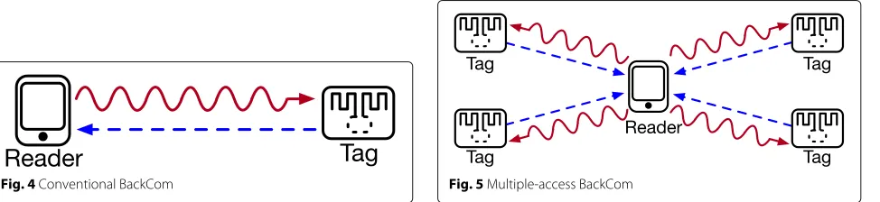
The conventional BackCom system discussed in Section2 is the simplest BackCom system, as illustrated in Fig.4. The next generation BackCom systems for IoT are much more complex and can be divided into the following categories.
3.1 Multiple-access BackCom systems
Many real-life applications can be modeled as a multiple-access (MAC) BackCom system where a single reader serves multiple tags, as illustrated in Fig.5. For instance, in a warehouse, an administrator can use a single reader to collect information simultaneously from hundreds or thousands of items equipped with RFID tags. In a smart city, a data aggregator can receive sensing data from a large number of backscatter sensors at the same time.
The key challenge in multiple-access BackCom systems is how to deal with collisions that arise as a result of concurrent tag transmissions. In this regard, a simple
Fig. 3The backward information-transmission mode of a BackCom link
solution is to avoid collisions between multi-tag trans-missions using the traditional MAC schemes includ-ing space/frequency/code/time-division multiple-access (SDMA/FDMA/CDMA/TDMA), see [6] and [12] and ref-erences therein.
In SDMA, the reader scans the space around it using directional antennas. The tags in the reading range are distinguished by their angular position. Therefore, the SDMA scheme requires large antenna arrays at the read-ers which increases the complexity. In FDMA, the tags adjust the frequency of alternation between two switch states on the order of hertz or kilohertz, and the reader detects tag’s signal in frequency domain. Thus, the FDMA scheme incurs high signal processing complexity due to the fast Fourier transform (FFT) computation. In CDMA, different tags use different orthogonal codes to modulate their signals. Due to the near-far problem, the tags of a CDMA network are required to do power control (i.e., to adjust the reflection coefficients) so as to achieve the same power level at the reader. This introduces higher proto-col complexity. Due to its simplicity, TDMA is perhaps the most practical scheme for MAC BackCom systems where tags transmit in separate pre-assigned time slots in each frame. The inherent closed-loop signaling for Back-Com facilitates the needed reader-tag synchronization for TDMA. Researchers have also attempted to design new MAC schemes exploiting the characteristics of BackCom. For instance, an interesting new method for collision avoidance was proposed in [13] for MAC BackCom that treats bursty backscatter transmissions by tags as a sparse code and decodes multi-tag data at the reader using a compressive-sensing algorithm.
Fig. 4Conventional BackCom
3.2 Ad hoc BackCom systems
To avoid unnecessarily overloading the core network and to reduce latency, distributed device-to-device or ad hoc communications is envisaged in future IoT, creating Back-Com interference channels. Back-Compared with conventional interference channels, a backscatter node reflects all inci-dent interference signals, resulting in interference regen-eration. The phenomenon is illustrated in Fig.6showing a two-link BackCom interference channel where readers 1 and 2 each transmit a CW to backscatter tags 1 and 2, respectively. In total, each reader, e.g., reader 1, is exposed to two interference components due to tag 2’s modulation and reflection of CWs from readers 1 and 2. In theory, the number of interference components received by each reader can increase as the square of the number of coex-isting links instead of linearly with the number in the conventional case. As a result, the interference issue is particularly severe in BackCom interference networks due to interference regeneration. One effective way for coping with this issue is to adoptspread spectrumtechniques in BackCom exploiting its low data rates [9].
3.3 Power beacon and ambient RF powered BackCom
systems
In the future IoT, most transmitting nodes are expected to be energy constrained and cannot act as readers to emit high-power CW and power their receivers nor to enable reader-to-tag transmissions. For IoT, there are two practical solutions for the power-source problem:
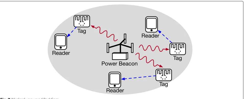
One solution is to deploy dense low-complexity and low-cost power beacons (PBs) dedicated for microwave
Fig. 6BackCom interference network
power transfer (MPT) [5], to enable BackCom links in their proximity by beaming towards them strong CWs, as illustrated in Fig.7. Then, the tag is able to perform RF energy harvesting and BackCom to the reader. Such Back-Com system is termed aswirelessly powered BackCom.
The other solution is to harvest the energy from ambi-ent RF signals, such as the signals from cellular, TV broadcasting and WiFi networks. Leveraging the ambient RF signals can allow direct tag-to-reader communication without readers supplying power, which has motivated various relevant designs recently [14]. For instance, a backscatter tag can transmit data to a peer by reflecting an incident base-station signal, as illustrated in Fig.8[15]. Therefore, instead of having some specific PBs or readers that enables tag-to-reader communications, the ambient backscatter system can use existing infrastructure and benefit from signals that are not intended for itself. Such
an energy-harvesting BackCom system differs from one with a reader or PB in two important aspects. First, the CW is replaced with a modulated signal and thus the reflection isdouble modulatedwith superimposed unin-tended and inunin-tended data. This problem can be tackled by exploiting the asymmetry in the high-rate ambient and low-rate backscatter signals. As result, the latter can be detected after suppressing the former by time averaging over each symbol duration. The second issue is the inci-dent ambient signal is much weaker than the CW from an intended reader or PB due to a much longer propagation distance. Consequently, BackCom with ambient RF sig-nal is suitable only for either short-distance or infrequent tag-to-reader communications.
3.4 BackCom systems with technology conversion
To communicate with passive tags embedded with differ-ent types of available commercialized devices, we envisage BackCom systems with technology conversion to become common place.
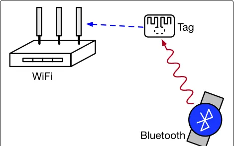
One technology conversion is to leverage a Bluetooth signal for BackCom between a tag and a WiFi device [16], as illustrated in Fig. 9. Consider a wearable-device network, which consists of an implanted BackCom sen-sor (i.e., a tag), a Bluetooth low energy (BLE) watch, and a smart phone, which is a WiFi device. Based on the BLE protocol, the Bluetooth watch can utilize one adver-tisement channel of the 2.4 GHz ISM band and adopt a Gaussian frequency shift keying (GFSK) method that encodes bits using two frequency tones [16]3. Hence, the
watch emits a CW at either of these frequency tones. By leveraging such CW-like Bluetooth signals, the BackCom tag can get its sensed e-health information collected by the smart phone through backscatter modulation. Although the Bluetooth CW frequency is usually different from
Fig. 8Ambient energy-harvesting BackCom
WiFi, by adopting a FSK modulation through properly switching between different impedances, the BackCom tag is able to shift the Bluetooth CW to the WiFi channel, hence achieving the BackCom with the smart phone.
Another technology conversion is to leverage WiFi. Consider a BackCom system for smart home applica-tions, which consists of a WiFi access point (AP) and a backscatter IoT sensor. The AP transmits packets to the WiFi clients, such as laptops and smart phones, which is also received by the backscatter IoT sensor. Then the sen-sor is able to modulate its data on the unintended signal and backscatters the signal to the AP. The double modu-lated backscattered signal is used by the AP, which obtains the tag’s information by removing its own transmitted information. In this way, sensors can be powered by WiFi APs and also rely on them to access the Internet even in the presence of access by WiFi devices, thereby providing inter-connectivity of everything for smart homes.
3.5 Comparison with a traditional system
In order to show the advantage of the next generation BackCom systems over traditional wireless sensor net-works (WSN), we consider the example of a wirelessly
Fig. 9BackCom system with technology conversion
powered BackCom system. Using MATLAB, we focus on a system-level simulation of an IoT network, where each IoT sensor node adopts either a backscatter circuit or a traditional RF circuit (including a mixer, DAC, and ampli-fier). Both types of the nodes are powered by a PB. The system level application of the simulation can be a smart supermarket. For example, the customers in a shopping mall/supermarket may use their smart phones (which act as readers) to collect information from different goods on the shelf (which are sent by tags).
The IoT nodes with a density of 0.2 nodes/m2are ran-domly distributed in a disk region with the radius of 5 m and served by the PB at the center. Each node aims to per-form sensing and transmission to its intended receiver at a fixed distance of 0.5 m. The IoT nodes adopt a harvesting-then-sensing-and-transmission task sequence per 100-ms time slot, where energy harvesting occupies 80 ms and the other operations 20 ms if there is sufficient energy.
Table 2Comparison of active components of BackCom and traditional IoT nodes
Sensor MCU Variable impedance DAC Mixer Power amplifier
Energy/power consumption 0.1μJ per sensing task 2.5μW 0.1μW 15μW 0.1 mW 50 mW
BackCom IoT node
Traditional IoT node
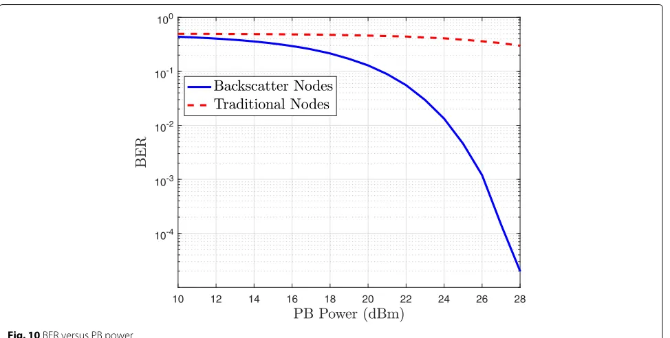
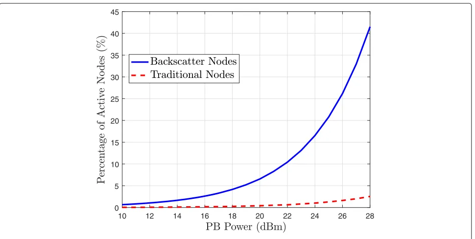
PB has a 25 dBm transmission power4. Figure11plots the percentage of active nodes. We see that the percentage of active IoT nodes increases with the PB’s transmit power, and the percentage of the active backscatter nodes is much larger than that of the traditional nodes. For example, the improvement of the percentage of active nodes is 7% when the transmit power is 20 dBm, and the improvement is 20% when the transmit power is 25 dBm. Therefore, the simulation results quantitatively show that the backscat-ter nodes can significantly improve the performance of the IoT network, and the wirelessly powered BackCom is a promising solution for future IoT applications. In the following section, we present more advanced BackCom techniques.
4 Emerging BackCom techniques
The future IoT applications require the BackCom systems to enable long-distance, low-latency, and high-rate com-munications between massive IoT devices and also enable their ad hoc communication. A few advanced BackCom techniques aiming at tackling these challenges are dis-cussed as follows.
4.1 BackCom systems with power beacons
Different from conventional RFID tags which only need to report its ID information, the IoT BackCom tags are also required to perform sensing and computing which can consume more energy. How to wirelessly power Back-Com using PBs (see earlier discussions) and maximize the power-transfer efficiency is a significant design issue.
The efficiency can be increased by energy beamform-ing from a multi-antenna PB and a tag. To this end, the PB needs to know the forward channel state information (CSI). For a free-space channel, the CSI reduces to the tag direction with respect to the PB. The PB can form a beam using the well-known retrodirective beamforming technique that automatically generates a beamformer by conjugating the observation of the pilot signal sent (i.e., reflected) by the tag. On the other hand, for a scattering channel, the beamformer designs are more complex but can exploit the so called “key-hole" channel structure due to backscattering (see e.g., [17]).
Another technique for improving the power-transfer efficiency is to optimize the CW waveform, e.g., as a weighted sum of multiple sinusoidal waves (see e.g., [18]).
Fig. 11Percentage of active nodes versus PB power
The design aims at increasing the peak-to-average power ratio of the PB signal that yields a higher energy-harvesting efficiency due to its non-linearity as a function of incident power.
4.2 Full-duplex BackCom
For future IoT, there would be massive number of tag-to-reader links existing at the same time. Though information flow in RFID applications is usually uni-directional, message exchange between nodes is common in IoT. Thus, full-duplex communication can substantially reduce the latency and improve the efficiency of spectrum utilization of the IoT-reader-to-tag links. For BackCom full-duplexing, there is a performance tradeoff between the transmission and the reception of a full-duplex Back-Com node. A smaller backscatter coefficient reduces the reflected signal power and thereby increases the received signal power, and vice versa.
There are two methods for implementing full-duplex BackCom. Both require a reader to have a full-duplex antenna allowing simultaneous transmission and recep-tion [19]. Consider simultaneous forward and backward information transmission in a BackCom system having one pair of reader and tag. For the first method, by lever-aging prior knowledge of forward information, the reader can cancel it in the backward information transmission signal and thereby retrieve the backward information. This method supports symmetric bidirectional data rates. The other method exploits the rate asymmetry in data transfer (tag to reader) and control signaling (reader to
tag). Specifically, the signals have different frequencies and can be decoupled by filtering or averaging, see [9] and references therein.
4.3 Time-hopping BackCom
As mentioned, interference in IoT networks with high node density poses a key design challenge that is exacer-bated by backscattering. For IoT devices which are sensors for smart cities and homes, the burstiness in their trans-missions can be exploited for tackling interference. A suitable transmission technique is time-hopping spread spectrum (TH-SS), where each tag randomly selects one ofN time slots for transmitting a single symbol and the choices of different tags are independent [9]. As a result, the number of simultaneous links is reduced by the factor
N, called the processing gain, thereby suppressing interfer-ence. An extreme form of TH-SS can be realized by ultra-wideband (UWB) transmission, where an extremely large processing gain is achieved using ultra-narrow pulses whose durations are in the order of nano-second.
4.4 MIMO BackCom
A key characteristic of the backward BackCom (i.e., the tag-to-reader information transmission) is the
to deploy antenna arrays at readers and tags and apply spatial-diversity techniques. Furthermore, multi-antennas can enhance the efficiency of wireless power transfer by enabling transmit energy beamforming and increasing receive antenna apertures.
Backscattering introduces a special channel structure for the backward information transmission in a multiple-input-multiple-output (MIMO) BackCom system, called adyadic MIMO channel, which captures the composite fading in the forward and backward channels [6]. To be specific, the CW signals sent by the transmit antennas of the reader propagate through the forward MIMO chan-nel and are first combined at each antenna of the tag and then backscattered, and lastly propagate through the backward MIMO channel to arrive at the receive anten-nas of the reader. The resultant dyadic MIMO channel has a similar structure as the classickeyhole MIMO chan-nel. The space-time coding is a simple but suitable tech-nique for achieving the diversity gain of such a channel. By adopting space-time coding, it has been proved that the achievable maximum diversity order is equal to the number of the tag’s antennas [6]. In other words, in con-trast to the conventional MIMO channel, increasing the number of receive antenna at the reader cannot continu-ously enhance the reliability of the backward information transmission.
5 IoT applications for BackCom
5.1 BackCom for smart homes/cities
Low-power or passive BackCom devices with energy-harvesting capabilities can be densely deployed to provide pervasive and uninterrupted sensing and computing ser-vices that provide a platform for implementing applica-tions for smart homes/cities.
In a smart home, a large number of passive BackCom sensors can be placed at flexible locations (e.g., embedded in walls, ceilings, and furniture). They are freed from the constraints due to recharging or battery replacements as one or multiple in-house PBs can be deployed to simulta-neously power all the sensors or otherwise they can oper-ate on ambient energy harvesting. The tasks performed by the sensors have a wide range such as detection of gas leak, smoke and CO, monitoring movements, indoor positioning, and surveillance [see Fig.12]. As an exam-ple, BackCom-based smart dustbins are able to monitor their trash levels and communicate the information to passing-by garbage trucks by backscattering, streamlin-ing the trash-collection process. Another example is that household robots are able to use the backscattered signals from the tags located on doors and furniture for indoor navigation [20].
In a smart city, ubiquitous BackCom sensor nodes can be placed in every city corner such as buildings, bridges, trees, street lamps, and parking areas. They can
Fig. 12BackCom application: smart home
streamline the city operations and improve our life quality via e.g., monitoring of air/noise pollution and traffic and parking-availability indicating. The efficient sensing-data fusion and wireless power for BackCom sensors can be realized by the deployment of integrated PBs and APs at fixed locations or mounted on autonomous ground vehi-cles or UAVs, providing full-city coverage without costly backhaul networks [21].
5.2 BackCom for biomedical applications
Fig. 13BackCom application: smart contact lens
5.3 BackCom for logistics
BackCom for logistics is a very attractive proposition due to the ultra-low manufacturing cost of simple and passive BackCom tags, as illustrated in Fig.14. For exam-ple, as early as 2007, the biggest 100 suppliers of the global renowned chain commercial group Wal-Mart have used the BackCom technology for logistics tracking. The technology has been helping the companies to substan-tially reduce operational cost, guarantee product quality, and accelerate the processing speed. In the past decade, the popularization and the application of BackCom have brought revolutionary changes to the logistics industry, due to its advantages compared with the conventional bar code technology, such as reduced manual control, long service lives, long reading distances, and encrypt-able and rewritable data.
Looking into the future, apart from the existing Back-Com techniques for logistics tracking and management, BackCom-based three-dimensional orientation tracking is
Fig. 14BackCom application: logistics management
an emerging technique. By attaching an array of low-cost passive BackCom tags as orientation sensors on the sur-face of the target objects, three-dimensional orientation information is available at the reader by analyzing the relative phase offset between different tags. In this way, human workers can be warned when the angle of a cargo is larger than a threshold.
6 Concluding remarks
IoT that aims to enable both the activity and the con-nectivity of billions of energy-consuming smart nodes, is challenged from the energy perspective. The BackCom systems and techniques provide promising solutions for tackling this challenge. In this article, we have introduced the basic principles for BackCom, summarized existing BackCom system and network architectures, and dis-cussed several emerging advanced BackCom techniques. Moreover, we have described various applications of Back-Com in IoT applications. With rapid advancements in both theory and applications, the technology is expected to play a key role in future IoT by enabling truly ubiq-uitous network connectivity, and pervasive sensing and computing.
Endnotes
1Note that the BackCom full-duplexing is different from
that of the conventional communication systems, and there is a performance tradeoff between the transmission and the reception of a full-duplex BackCom node, which will be discussed in Section4.2
2BackCom Readers are typically connected to the
power grid or equipped with large capacity batteries.
3Note that a typical Bluetooth device uses frequency
4This PB transmit power is practical. This is because
according to FCC regulations, the transmission power should be less than 30 dBm for omnidirectional transmis-sion.
Abbreviations
AP: Access point; BackCom: Backscatter communications; BLE: Bluetooth low energy; BPSK: Binary phase-shift keying; CDMA: Code-division multiple-access; CSI: Channel state information; CW: Continuous wave; FDMA: Frequency-division multiple-access; GFSK: Gaussian frequency shit keying; MAC: Multiple access; OFDMA: Orthogonal frequency-division multiple-access; PB: Power beacon; PT: Power transfer; RF: Radio-frequency; RFID: Radio-frequency identification; SDMA: Space-division multiple-access; TDMA: Time-division multiple-access; TH-SS: Time-hopping spread spectrum; UAV: Unmanned aerial vehicle; UWB: Ultra-wideband; WSN: Wireless sensor networks
Funding
The work of W. Liu was supported by the Australian Research Council’s Australian Laureate Fellowships scheme (project number FL160100032). The work of K. Huang was supported by Hong Kong Research Grants Council under the Grants 17209917 and 17259416. The work of S. Durrani and X. Zhou was supported by the Australian Research Council’s Discovery Project Funding Scheme (Project number DP170100939).
Authors’ contributions
KH and WL came up with the original idea. WL drafted the manuscript under the supervision of KH. XZ and SD helped to further refine the manuscript. All authors read and approved the final manuscript.
Competing interests
The authors declare that they have no competing interests.
Publisher’s Note
Springer Nature remains neutral with regard to jurisdictional claims in published maps and institutional affiliations.
Author details
1School of Electrical and Information Engineering, The University of Sydney,
Sydney, NSW 2006, Australia.2Department of Electrical and Electronic
Engineering, The University of Hong Kong, Hong Kong, China.3Research
School of Engineering, The Australian National University, Canberra, ACT 2601, Australia.
Received: 2 July 2018 Accepted: 28 February 2019
References
1. S. Sudevalayam, P. Kulkarni, Energy harvesting sensor nodes: survey and implications. IEEE Commun. Surv. Tuts.13(3), 443–461 (2011) 2. A. N. Parks, A. P. Sample, Y. Zhao, J. R. Smith, in2013 IEEE Topical
Conference on Biomedical Wireless Technologies,Networks, and Sensing Systems. A wireless sensing platform utilizing ambient RF energy (IEEE, 2013), pp. 154–56
3. R. Vyas, H. Nishimoto, M. Tentzeris, Y. Kawahara, T. Asami, in2012 IEEE/MTT-s International Microwave Symposium Digest. A battery-less, energy harvesting device for long range scavenging of wireless power from terrestrial TV broadcasts (IEEE, 2012), pp. 1–3
4. PowerSpot (2017).https://www.powercastro.com/wp-content/uploads/ 2018/06/TX91503-UserManualREV4.pdf. Accessed Dec 2017
5. K. Huang, X. Zhou, Cutting the last wires for mobile communications by microwave power transfer. IEEE Communications Magazine.53(6), 86–93 (2015)
6. C. Boyer, S. Roy, Backscatter communication and RFID: coding, energy, and MIMO analysis. IEEE Transactions on Communications.62(3), 770–785 (2014)
7. CC2520 DATASHEET (2007).http://www.ti.com/lit/ds/symlink/cc2520.pdf. Accessed Dec 2007
8. U. Karthaus, M. Fischer, Fully integrated passive UHF RFID transponder IC with 16.7-μw minimum RF input power. IEEE Journal of solid-state circuits.38(10), 1602–08 (2003)
9. W. Liu, K. Huang, X. Zhou, S. Durrani, Full-duplex backscatter interference networks based on time-hopping spreading spectrum. IEEE Transactions on Wireless Communications.16(7), 4361–4377 (2017)
10. DG2012 DATASHEET (2007).http://www.vishay.com/docs/72176/ dg2012.pdf. Accessed 30 Apr 2017
11. N. V. Huynh, D. T. Hoang, X. Lu, D. Niyato, P. Wang, D. I. Kim, Ambient backscatter communications: a contemporary survey. IEEE Communications Surveys & Tutorials.20(4), 2889–2922 (2018) 12. A. Bletsas, S. Siachalou, J. N. Sahalos, Anti-collision backscatter sensor
networks. IEEE Trans. Wireless Commun.8(10), 5018–5029 (2009) 13. J. Wang, H. Hassanieh, D. Katabi, P. Indyk, inProceedings of the ACM
SIGCOMM 2012 conference on Applications,technologies,architectures, and protocols for computer communication. Efficient and reliable low-power backscatter networks (ACM, 2012), pp. 61–72
14. V. Liu, A. Parks, V. Talla, S. Gollakota, D. Wetherall, J. R. Smith, Ambient backscatter: wireless communication out of thin air. ACM SIGCOMM Comput. Commun. Rev.43(4), 39–50 (2013)
15. W. Liu, Y. C. Liang, Y. Li, B. Vucetic, Backscatter multiplicative multiple-access systems: fundamental limits and practical design. IEEE Trans. Wirel. Commun.17(9), 5713–5728 (2018)
16. V. Iyer, V. Talla, B. Kellogg, S. Gollakota, J. Smith, inProceedings of the 2016 ACM SIGCOMM Conference. Inter-technology backscatter: Towards internet connectivity for implanted devices (ACM, 2016), pp. 356–369 17. G. Yang, C. K. Ho, Y. L. Guan, Multi-antenna wireless energy transfer for backscatter communication systems. IEEE Journal on Selected Areas in Communications.33(12), 2974–2987 (2015)
18. B. Clerckx, E. Bayguzina, Waveform design for wireless power transfer. IEEE Transactions on Signal Processing.64(23), 6313–6328 (2016)
19. A. Sabharwal, P. Schniter, D. Guo, D. W. Bliss, S. Rangarajan, R. Wichman, In-band full-duplex wireless: Challenges and opportunities. IEEE J. Sel. Areas Commun.32(9), 1637–1652 (2014)
20. J. J. Pomárico-Franquiz, Y. S. Shmaliy, Accurate self-localization in RFID tag information grids using FIR filtering. IEEE Trans. Ind. Informat.10(2), 1317–1326 (2014)