Low-Complexity Decoding of Block Turbo-Coded
System with Antenna Diversity
Yanni Chen
Department of Electrical and Computer Engineering, University of Minnesota, 200 Union Street, Minneapolis, MN 55455, USA Email:[email protected]
Keshab K. Parhi
Department of Electrical and Computer Engineering, University of Minnesota, 200 Union Street, Minneapolis, MN 55455, USA Email:[email protected]
Received 29 January 2003 and in revised form 30 April 2003
The goal of this paper is to reduce the decoding complexity of space-time block turbo-coded system with low performance degra-dation. Two block turbo-coded systems with antenna diversity are considered. These include the simple serial concatenation of error control code with space-time block code, and the recently proposed transmit antenna diversity scheme using forward error correction techniques. It is shown that the former performs better when compared to the latter in terms of bit error rate (BER) under the same spectral efficiency (up to 7 dB at the BER of 10−5for quasistatic channel with two transmit and two receive anten-nas). For the former system, a computationally efficient decoding approach is proposed for the soft decoding of space-time block code. Compared to its original maximum likelihood decoding algorithm, it can reduce the computation by up to 70% without any performance degradation. Additionally, for the considered outer code block turbo code, through reduction of test patterns scanned in the Chase algorithm and the alternative computation of its extrinsic information during iterative decoding, extra 0.3 dB to 0.4 dB coding gain is obtained if compared with previous approaches with negligible hardware overhead. The overall decoding complexity is approximately ten times less than that of the near-optimum block turbo decoder with coding gain loss of 0.5 dB at the BER of 10−5over AWGN channel.
Keywords and phrases:block turbo code, space-time block code, low-complexity decoding, soft decoding.
1. INTRODUCTION
One of the major challenges in wireless communications is the severe channel fading caused by multipath and move-ment in radio link. Recently, in order to explore the improved capacity of multiple-in multiple-out (MIMO) system over flat Rayleigh fading channel [1], different transmit diversity techniques have been developed to benefit from antenna di-versity in the downlink while placing the didi-versity burden on the base station [2,3]. Although space-time block code (STBC) has attracted a lot of attention, few papers have been published on its hardware implementation. The authors in [4] addressed the hard decoding of STBCs, which is based on the maximum likelihood decoding algorithm presented in [3].
STBC provides the maximum possible diversity advan-tage for multiple transmit antenna system with a very low complexity decoding algorithm. However, in order to achieve significant coding gain, it should be concatenated with a
powerful outer code [5,6, 7]. The current powerful error control codes use iterative soft-input soft-output (SISO) de-coding to achieve performance approaching Shannon limit. Thus, the concatenated STBC decoder must provide soft out-put, that is, the reliability information of the decision bit, to the SISO block turbo decoder. Therefore, efficient soft de-coding algorithm for STBC should be considered.
In [8], a near-optimum iterative algorithm for decoding block turbo codes (BTCs) was proposed, which is based on the chase algorithm [9]. Unfortunately, in spite of its near-optimum performance comparable to convolutional turbo code (CTC) [10], the decoding complexity is fairly high. In
order to offer a compromise between performance and
com-plexity, several complexity reduction schemes have been dis-cussed and presented [11,12,13,14,15,16].
Source Block turbo
computation Deinterleaving Block turbodecoder Sink
Figure1: Space-time block turbo-coded system (BTC-STBC system).
coding gains, BTCs associated with transmit and receive di-versity (BTC-Didi-versity system) performs as well as CTC. In this paper, the serial concatenation of BTC-STBC system is simulated, which achieves additional coding gain compared to BTC-Diversity system under the same spectral efficiency (up to 7 dB at the bit error rate (BER) of 10−5over quasistatic
channel with two transmit and two receive antennas). STBC with code rate 1 is chosen to preserve the code rate of the whole system.
In this paper, a new efficient decoding approach is pro-posed for STBC. It introduces no performance degrada-tion and requires much lower hardware complexity, which is more suitable for real implementation. For the chosen outer error control code, BTC, we also present a new power effi -cient method which gains an extra 0.3 dB to 0.4 dB coding gain compared to the scheme presented in [12]. The hard-ware overhead is negligible. This implies that the complex-ity of our new block turbo decoder is about ten times less
than that of the near-optimum block turbo decoder [19]
with a performance degradation of only 0.5 dB at the BER
of 10−5 over additive white Gaussian noise (AWGN)
chan-nel. Thus, the very large scale integration (VLSI) implemen-tation of the space-time block turbo-coded system with low complexity and acceptable error correction capability is pos-sible.
This paper is organized as follows. In Section 2, two space-time block turbo-coded systems are briefly introduced and their performances are compared under the same spec-tral efficiency over block fading or quasistatic fading channel with two transmit and one or two receive antennas.Section 3
presents the complexity reduction approaches for soft de-coding of STBC in the system with better BER performance.
Section 4is devoted to the complexity reduction schemes for the block turbo decoder.Section 5provides the conclusions.
2. SPACE-TIME BLOCK TURBO-CODED SYSTEMS
In this section, space-time block codes with maximum like-lihood decoding algorithm are briefly explained and the per-formances of the two space-time block turbo-coded systems are compared under the same spectral efficiency.
Assuming that flat Rayleigh fading matrix channel and perfect channel state information is available, the log a pos-teriori probability (LAPP) of the two transmitted symbolsc1
andc2for the STBC with two transmit antennas is given as
follows [5]:
for the symbolc2, wherertjis the signal received at antenna j at each time slott,hi, jis the path gain from transmit antenna
i, 1≤i≤n, to receive antenna j, 1 ≤ j ≤m, andskis the possible complex constellation symbol.
2.1. BTC-STBC system versus BTC-Diversity system
Simple STBC concatenated with powerful forward error cor-rection channel code as outer code is expected to provide sig-nificant coding gain in addition to the diversity advantage. The block diagram of space-time block turbo-coded system is illustrated inFigure 1.
At the receiver end, the output from STBC decoder is the LAPPs for each transmitted symbol. Before it is input to the block turbo decoder, the log-likelihood ratios (LLRs) for in-dividual bits have to be calculated, which resembles the re-verse function of gray mapping in transmit antenna,
Source Block turbo
Figure2: BTC for transmit antenna diversity (BTC-Diversity system).
Another considered BTC for transmit antenna diversity
system is shown in Figure 2. This straightforward system
is chosen because it has recently drawn much interest and achieves much better performance compared to the original space-time trellis code [17]. Denoting the set of constellation points by{ci}2
M
i=1, the LLRs ofbl,l=1,2, . . . , nM, usingm re-ceived signals fromntransmit antennas, can be obtained as (see [17])
whereN0stands for the noise power spectral density. To sim-plify the computation complexity, the following approximate equation is used in our simulation:
∧bl
Both BTC-Diversity and BTC-STBC systems have much flexibility since the block turbo decoder remains the same no matter which type of modulation scheme or fading chan-nel is employed. Nevertheless, BTC-STBC system has two more building blocks (space-time block encoder and de-coder). Furthermore, some modifications have to be made to the STBC codec if the number of transmit antennas is in-creased.
However, the overall complexity of the BTC-STBC sys-tem is not increased as the LLR computation module is much simpler. From (5) and (6), it is easily seen that the number of computationsNrequired to obtain the LLRs for each bit in BTC-Diversity grows exponentially with the constellation size 2M(N=2M×n, wherenstands for the number of trans-mit antennas). On the other hand, for BTC-STBC system, this number grows only linearly (N =2M), instead of expo-nentially, with the constellation size (see (1), (2), and (3)).
For example, if 16-QAM is adopted for both systems with two transmit antennas, 256 comparison terms have to be cal-culated for BTC-Diversity system, while only 16 comparison terms need to be calculated for BTC-STBC system. This sig-nificant hardware reduction is very attractive for VLSI imple-mentation.
2.2. Performance comparison under the same spectral efficiency
The considered BTC is composed of two identical system-atic extended Hamming code [exHamming(32,26,4)]2with
code rate R = 0.660. STBC is defined by the
transmis-sion matrix G2 as [2]. Helical interleaver as described in [20] is employed in our simulation. For fair comparison, the spectral efficiencies for the two systems are kept the same. In the case of two transmit antennas, BTC-STBC sys-tem transmits two symbols in two time slots while BTC-Diversity system transmits two symbols in just one time slot. Therefore, for 2Rbits/s/Hz (1.32 bits/s/Hz), BTC-STBC uses QPSK while BTC-Diversity uses BPSK modulation. For 4Rbits/s/Hz (2.64 bits/s/Hz), BTC-STBC uses 16-QAM while
BTC-Diversity uses QPSK modulation. Here,Rrefers to the
code rate of BTC.
All the performance are evaluated over either the block fading channel or quasistatic fading channel. Here, block fading channel means that the path gains are
con-stant for consecutive L channel symbols, where L is
smaller than frame length (1024 bits for our considered [exHamming(32,26,4)]2 code). These L adjacent symbols
are also called a faded block since they are affected by the same fading value. On the other hand, quasistatic fading channel means that the path gains are constant for a frame and change independently from one frame to the next. Ac-tually, quasistatic channel is a special case of block fading channel, whereLis equal to frame length. Two differentL
values are simulated: 2 or 64. The case of L = 2
guaran-tees the validity of the decoding algorithm of STBC, which is based on the assumption that the path gains are con-stant over two successive transmissions. While the case of
5 10 15 20 SNR (dB)
10−6 10−5 10−4 10−3 10−2 10−1
BER
QPSK, BTC-STBC (L=2) BPSK, BTC-Diversity (L=2) QPSK, BTC-STBC (L=64)
BPSK, BTC-Diversity (L=64) QPSK, BTC-STBC (quasi) BPSK, BTC-Diversity (quasi)
(a)
10 15 20
SNR (dB) 10−6
10−5 10−4 10−3 10−2 10−1
BER
QPSK, BTC-STBC (L=2) BPSK, BTC-Diversity (L=2) QPSK, BTC-STBC (L=64) BPSK, BTC-Diversity (L=64)
(b)
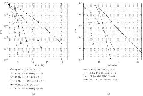
Figure3: BER comparison for BTC-STBC system and BTC-Diversity system: 2Rbits/s/Hz, 4 iterations, two transmit antennas, and (a) two or (b) one receive antennas.
The BER comparison of the two transmit and two receive antennas with 2Rbits/s/Hz over different channels is shown inFigure 3a.
AsLincreases, the SNR has to be increased accordingly to maintain the same BER performance. At the BER of 10−5, the
advantage of BTC-STBC over BTC-Diversity system is only around 1.5 dB overL=2 andL=64 block fading channels, while this additional coding gain is up to 8 dB over quasistatic channel.
Similar results are obtained for two transmits and one re-ceive antenna case (Figure 3b). For theL = 2 block fading channel, BTC-STBC system demonstrates additional coding gain of 3 dB at the BER of 10−5. This extra coding gain is
6 dB overL=64 block fading channel. More coding gain is expected over quasistatic fading channel.
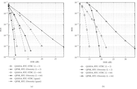
InFigure 4, spectral efficiency is increased to 4Rbits/s/Hz
from 2Rbits/s/Hz. Significant coding gains of BTC-STBC
system over BTC-Diversity system are also observed. At the BER of 10−5, for two transmit and two receive antenna, the
coding gain is 2 dB over L = 64 block fading channel and
7.5 dB over quasistatic fading channel. It is interesting to note that asL=2, the performance of the two systems are com-parable. For two transmit and one receive antennas system, the coding gain is 4 dB overL=2 block fading channel and 11 dB overL=64 block fading channel.
3. COMPLEXITY REDUCTION OF SPACE-TIME BLOCK DECODER
In this section, a powerful efficient algorithm is described for evaluating the bit LLRs in (3). As an example, the trans-mission matrix for two transmit antennasG2[2] and BPSK, QPSK, and 16-QAM modulation schemes are adopted here. Similar approaches can be easily applied to other transmis-sion matrices and modulation schemes.
Denotingsk=sI+jsQ, we can rewrite the decision metric used for the LAPP computation in (3) as
Mc, sk
=(α+jβ)−sk2+γsk2
=α2+β2−2αs
I+βsQ
+ (γ+ 1)s2
I+s2Q
, (7)
where
α+jβ=
m
j=1
r1hj ∗2, j−
r2j
∗
h1, j forc1,
or m
j=1
r1hj ∗1, j+
r2j
∗
h2, j forc2,
γ=
−1 +m
j=1 2
i=1 hi, j2
.
10 15 20 25 SNR (dB)
10−6 10−5 10−4 10−3 10−2 10−1
BER
QAM16, BTC-STBC (L=2) QPSK, BTC-Diversity (L=2) QAM16, BTC-STBC (L=64) QPSK, BTC-Diversity (L=64) QAM16, BTC-STBC (quasi) QPSK, BTC-Diversity (quasi)
(a)
15 20 25 30
SNR (dB) 10−6
10−5 10−4 10−3 10−2 10−1
BER
QAM16, BTC-STBC (L=2) QPSK, BTC-Diversity (L=2) QAM16, BTC-STBC (L=64) QPSK, BTC-Diversity (L=64)
(b)
Figure4: BER comparison for BTC-STBC system and BTC-Diversity system: 4Rbits/s/Hz, 4 iterations, two transmit antennas and (a) two or (b) one receive antennas.
From (7), further simplifications can be made as follows: (1) the termα2+β2 is common for alls
k, thus, it can be excluded from the comparisons;
(2) for M-PSK with equal energy signal constellations, (γ+ 1)(s2
I+s2Q) can also be cancelled out. Then,
∧bl
=2 max
sk|bl=1
αsI+βsQ
−2 max
sk|bl=0
αsI+βsQ
. (9)
From (9), it is observed that the bit LLRs for M-PSK are
only dependent on values of α,βand modulation scheme
which decidessIandsQ. In the following, the computation of those bit LLRs for each considered modulation scheme will be described, respectively.
3.1. BPSK and QPSK
The signal constellations for BPSK and QPSK are illustrated inFigure 5. Gray mapping is assumed.
As seen inFigure 5, there is no complex signal for BPSK constellations, that is,sQ =0. According to (9), the bit LLR for BPSK case is
∧(b)≈2α−2α(−1)=4α. (10)
In a straightforward manner, the two bit LLRs for QPSK
are simplified as follows:
∧b1≈2 max s3,s2
αsI+βsQ
−2 max
s1,s0
αsI+βsQ
=2α+ max s3,s2
βsQ
−2−α+ max
s1,s0
βsQ
=4α,
∧b0≈2 max s3,s1
αsI+βsQ
−2 max
s2,s0
αsI+βsQ
=2β+ max
s3,s1
αsI −2
−β+ max
s2,s0
αsI =4β. (11)
3.2. 16-QAM
The signal constellations for 16-QAM are illustrated in
Figure 6. Gray mapping is also assumed.
For the 16-QAM case, due to the unequal signal energies of constellations, the term (γ+ 1)(s2
I +s2Q) in (7) has to be considered for comparisons. For the first bitb0, we have
∧b0≈ max sk|b0=1
2αsI+βsQ
−(γ+ 1)s2
I+s2Q
− max sk|b0=0
2αsI+βsQ
−(γ+ 1)s2
I+s2Q
. (12)
.
Figure5: Signal constellations of BPSK and QPSK.
.
Figure6: Signal constellations and mapping of 16-QAM.
determined just by observing the signs ofαandβ. Therefore, there are merely four cases. Ifα >0 andβ >0,
The reason for the second step is that the pointss2and
s3,s6 ands7 have the same sQ value. In the third step, the
two maximum terms can always be cancelled out since the two finally chosen points will have the samesIvalues. By the same method,∧(b0) can be computed for three other cases, that is, (i)α >0 andβ < 0, (ii)α <0 andβ > 0, and (iii)
One general expression can be used to summarize all the re-sults:
∧b0≈sign(β)∗4β−8(γ+ 1). (15)
Similarly, the LLR for the second bitb1is
∧b1≈sign(α)∗4α−8(γ+ 1). (16)
However, for the other two bitsb2 andb3, it is slightly more complicated since the compared signal constellations are not located in four different quadrants. For the fourth bitb3, the eight compared signals are symmetric along theI -axis. Thus, four of them can be eliminated by just observing the sign ofβ. The remaining four points in each compared group are always simultaneously in the lower or upper plane and symmetric along theQ-axis. Consequently,sQcan always be cancelled out, that is,∧(b3) depends only on the sign, not on the absolute value ofβ. Ifβ >0,
it is already cancelled out in the decision metric. As a result, the procedure to compute∧(b3) has the following two steps. First, calculate the bias points: bias=2∗(1+γ),α1=α−bias, α2 = α+ bias. Secondly, observe the signs ofα1 andα2to
compute the right soft output. Consequently, there are four possible cases:
(1) if (α1>0 andα2>0),
∧b3≈2αsI−(γ+ 1)s2Is3−
2αsI−(γ+ 1)s2Is1
=2α∗3−9(γ+ 1)−2α∗(−1)−(γ+ 1)
≈8α−8(γ+ 1);
(19)
(2) else if (α1>0 andα2<0),
∧b3≈2α(3)−9(γ+ 1) +2α(3) + 9(γ+ 1)=12α; (20)
(3) else if (α1<0 andα2>0),
∧b3≈2α−(γ+ 1)−2α∗(−1)−(γ+ 1)=4α; (21)
(4) else
∧b3≈2α−(γ+ 1)−2α∗(−3)−9(γ+ 1)∧b3 ≈8α+ 8(γ+ 1).
(22)
In a similar approach, the LLR for the third bit is cal-culated. Nevertheless, the cancelled-out terms here aresI in-stead ofsQ:
∧b2≈max s0−s7
2βsQ−(γ+ 1)s2Q
−max
s8−s15
2βsQ−(γ+ 1)s2Q
.
(23)
The bias points are bias = 2∗(1 +γ),β1 = β−bias, β2=β+ bias. Then, the soft output is
(1) if (β1>0 andβ2>0),∧(b2)≈8β−8(γ+ 1);
(2) else if (β1>0 andβ2<0),∧(b2)≈12β;
(3) else if (β1<0 andβ2>0),∧(b2)≈4β;
(4) else∧(b2)≈8β+ 8(γ+ 1).
In other words, all the three variablesα, β, and γ are required to compute the LLRs for 16-QAM modulation. However, through the bias point calculation approach, many comparisons among half constellation size of signals have been avoided.
3.3. Complexity analysis
In this section, the hardware complexity between the origi-nal and proposed maximum likelihood decoding algorithm will be compared. The complexity considered here is in terms of the number of multiplications and additions for each de-coded symbol. The following assumptions are used as in [4].
Table1: Complexity comparison between original and proposed decoding algorithm.
Total number of iterations BPSK QPSK 16-QAM Original algorithm 28N−2 32N+ 6 68N+ 34 Proposed algorithm 8N−1 16N−2 24N+ 6 Computation reduction (N=8) 72% 52% 66%
(1) The word length of the operands isNbits.
(2) Addition and subtraction or comparison are counted as one operation and real multiplication or square op-eration is counted as (N−1) operations. Multiplied by 2, 4, or 8 is neglected since it can be implemented as simple shift operation in hardware.
(3) A complex multiplication is counted as 4 multiplica-tions and 2 addimultiplica-tions, that is, (4N−2) operations, in-cluding real or imaginary parts, each equal (2N−1) operations.
(4) The signal energies for BPSK and QPSK are assumed to be known in advance and their computations are ex-cluded from complexity count. For the 16-QAM case, the signal energies and its multiplication withγ are only counted for 4 instead of 16 times due to the in-herent symmetry property.
The comparison results are displayed inTable 1. For
ex-ample, for BPSK case, in the proposed algorithm, only α
needs to be computed to obtain the soft output ∧(b). For the symbol c1 in (8), the computation of the real part of
r1hj ∗2, jand (r j
2)∗h1, jfor two transmit antennas,j=1,2, needs (2N−1)×4=(8N−4) operations. Three more additions are necessary to obtainα, thus, the overall decoding com-plexity is (8N−4) + 3=(8N−1) operations. While in the original algorithm, for the symbolc1,α+ jβfor two trans-mit antennas requires (8N−1)×2=(16N−2) operations. Additionally, (2N−1)×4 + 1 = (8N−3) operations for
γand 2×(N−1) + 2 =2Noperations for each compared
signalsk; another three additions for final soft output are re-quired (see (1) and (3)). The total number of operations is (16N−2) + (8N−3) + 2N×2 + 3=(28N−2). By using sim-ilar method, the total number of operations for QPSK and 16-QAM with both the original and proposed algorithms can also be obtained.
As observed in Table 1, the new proposed soft
decod-ing algorithm for STBC with two transmit antennas reduces the total number of operations by 52% to 72%. Similar re-sults are expected for other transmission matrices with more transmit antennas. This significant computation reduction will consequently cause much lower power consumption in VLSI implementation.
According to our simulation results under various con-figurations, the proposed simplified soft decoding approach achieves exactly the same performance as the original max-imum likelihood algorithm for space-time block decoder
shown in Section 2, which is omitted here. On the other
4. COMPLEXITY REDUCTION OF BLOCK TURBO DECODER
Since our major goal in this paper is to reduce the decoding complexity of the space-time block turbo-coded system, in
Section 3, the simplified decoding algorithm is already pro-posed and evaluated for the space-time block decoder. In this section, we investigate the complexity reduction issues for the block turbo decoder.
4.1. Iterative decoding of BTCs based on Chase algorithm
BTC is also called turbo product code, which is decoded by sequentially decoding the rows and columns in order to reduce the decoding complexity based on the Chase algo-rithm [9]. The main idea of the Chase algorithm is to limit
the number of reviewed codewords to codeword subset Ω
formed by the following steps.
step 1: Determinepleast reliable positions using channel in-formationR.
step 2: Form the 2pbinaryn-tuple test patternsTat thepleast reliable positions.
step 3: Decode test sequencesZq =r⊕tqusing an algebraic decoder to form subsetΩ.
To maintain the near-optimum performance, the itera-tive SISO approach is employed. The soft input to the de-coderR(m) is
R(m)=[R] +α(m)×W(m), (24)
wheremis the decoding step,Ris the received channel infor-mation,W(m) is the extrinsic information input to the next iteration, andα(m) is the scaling factor which takes a small value in the first decoding step and increases as the BER tends to zero. The extrinsic information is the difference between soft output (normalized LRR) and soft input of the decoder and is calculated as follows:
wj(m)=
R(m)−C2
−R(m)−D2
4 ×dj−rj(m) (25)
or
wj(m)=β×dj, (26)
whenCdoes not exist in the considered subset, whereDis
the maximum likelihood decoded (MLD) codeword,Cis the
competing codeword ofD, that is,Chas also minimum dis-tance toRbutcj =dj, andβis the empirically determined reliability factor.
4.2. Complexity reduction techniques
For the block turbo decoder described above, we can see that there are two major sources of complexity. If we con-sider the decoding of a column of the matrix, the first source lies in step 3 of the procedures to find the codeword subset
Ω. For this column, each ofq = 2p formed test sequences has to perform one syndrome decoding, that is, the decoding
complexity of one column for this procedure isq×mtimes
the complexity of a syndrome decoder, wheremstands for
the number of decoding steps.
The second source of complexity is the extensive compu-tation of the extrinsic informationW(m) associated with the MLD codewordD. For eachwj, this procedure has to search
among theqcodewords in the codeword subsetΩwhether
there is a competing codeword C at the smallest distance
fromRsuch thatcj =dj. Thus,Dis unique to all symbols ofR, whileCmay be different for each symbol. If we findC, then we use (25), else we use (26) to computewj. The decod-ing complexity of one column for this second procedure is
q×n×mtimes the complexity of an elementary compare and save operation, wherenstands for the block length. There-fore, in order to reduce the complexity of the block turbo decoder, we can either decrease the number of test patternsq
or simplify the extrinsic information computation.
4.2.1. Simplifying the extrinsic information computation
We first look at the second possibility. To avoid searching the competing codewordCfor each symbol of the block code, it can be replaced by the MLD codeword of last decoding step
D(m−1) when computing the extrinsic information, which is called gradient algorithm [12]. In terms of complexity re-duction, this is a very clever way since the decoding complex-ity of one column for the second procedure is reduced down
ton×mtimes the complexity of an elementary compare and
save operation, that is, the complexity is decreased by more than ten times. Nevertheless, its drawback is that the replaced competing codewordC=D(m−1) is not always a codeword. The decoder guarantees that we have codewords along the rows (columns) of the matrix in the current decoding step but not along the columns (rows) in the next decoding step. Thus, there is no guarantee thatW(m+1) has the same inter-pretation in this gradient algorithm as in the near-optimum one.
A new gradient algorithm is proposed to compute the ex-trinsic information without searching the competing
code-word C extensively [15]. The main idea is to divide the
codeword matrix [D(m)] into codeword matrix for columns [Dcol(m)] and for rows [Drow(m)]. We consider themth de-coding step of the BTC and suppose that we start by decod-ing the columns of the BTC. For odd values ofm, the decoder processes the columns of the block turbo code as follows:
wj(m+ 1)
=R(m)−Dcol(m−1) 2
−R(m)−Dcol(m)2 4
×dcolj(m)−rj(m)
(27)
whendcolj(m)=dcolj(m−1), otherwise we use
while for even values ofm, the decoder processes the rows of BTC
wj(m+ 1)
=R(m)−Drow(m−1) 2
−R(m)−Drow(m)2 4
×drowj(m)−rj(m)
(29)
whendrowj(m)=drowj(m−1), otherwise we use
wj(m+ 1)=β×drowj(m) withβ≥0. (30)
Here is another interpretation of this algorithm. Since the rows and columns of the BTC are always decoded alterna-tively, one after another, the new proposed algorithm can be equivalently considered as usingD(m−2) instead ofD(m−1) to compute extrinsic informationW(m+ 1):
wj(m+ 1)=
R(m)−D(m−2)2
−R(m)−D(m)2 4
×dj(m)−rj(m),
(31)
form≥2, whendj(m)=dj(m−2), otherwise we use
wj(m+ 1)=β×dj(m) withβ≥0. (32)
Whenm <2, the nongradient algorithm can be used. Com-pared to the gradient algorithm in [12], this new algorithm guarantees that the matrix [Dcol(m−1)] or [Drow(m−1)] is always a codeword. As a result, the performance is better. In fact, an extra 0.3 dB to 0.4 dB coding gain is obtained. The hardware overhead is negligible since only one small buffer is needed to store the single bit codeword information.
4.2.2. Reducing the number of test patterns
For the first possibility, using the algebraic structure of ex-tended Hamming codes that consist of BTCs and the syn-drome of a received word in a component code, one can show that the required numberN(p, d) of test patterns is as follows [11]:
(1) no error detection:N(p, d)=2(p−1)+ 1−p,
(2) single error detection:N(p, d)=2(p−1),
(3) double error detection:N(p, d)=2(p−1)+ 1,
where pis the number of least reliable bits scanned in the
Chase algorithm and d is the number of algebraically
de-tected errors in a received word. In this way, the required number of test patterns decreases from 2p toN(p, d). An-other important feature of this reduction scheme is that it eliminates only the unnecessary test patterns without chang-ing the codeword subsetΩfor a fixedp. Consequently, it re-sults in no performance degradation.
1 2 3 4 5 6 7 8
Eb/N0(dB) 10−6
10−5 10−4 10−3 10−2 10−1
BER
Uncoded
Old gradient(iter 1) New gradient(iter 1) Old gradient(iter 2) New gradient(iter 2) Old gradient(iter 4) New gradient(iter 4)
Near optimum (8 test patterns) Near optimum (16 test patterns)
Figure7: BER versusEb/N0of [exHamming(32,26,4)]2using dif-ferent gradient algorithms.
4.3. Simulation results
Two BTCs are considered for performance evaluation, one is [exHamming(32,26,4)]2 with rate 0.660 and the other
is [exHamming(64,57,4)]2 with rate 0.793. All the
perfor-mance are evaluated on the AWGN channel with QPSK mod-ulation. Before proceeding to the simulation results, we will now give the different parameters used in our simulation:
(1) the number of test patternsqis 8 and are generated by thep=4 least reliable bits;
(2) α=[0.0,0.2,0.3,0.4,0.8,0.9,1.0,1.0]; (3) β=[0.2,0.4,0.6,0.7,0.8,0.9,1.0,1.0];
(4) the maximum iteration number is 4, which is equiva-lent tom=8 decoding steps.
The performance comparison between our new gradient algorithm and that in [12] for the [exHamming(32,26,4)]2
and [exHamming(64,57,4)]2 BTC is shown in Figures 7
and 8, respectively. From these two figures, extra coding gain can be clearly observed with our new gradient al-gorithm using separate row and column MLD codeword matrices compared with that using only one codeword
matrix. At the BER of 10−5, the extra coding gain is
0.4 dB for [exHamming(32,26,4)]2 BTC and 0.3 dB for
2 2.5 3 3.5 4 4.5 5 5.5 6 6.5 7
Eb/N0(dB) 10−6
10−5 10−4 10−3 10−2 10−1
BER
Uncoded
Old gradient(iter 1) New gradient(iter 1) Old gradient(iter 2) New gradient(iter 2) Old gradient(iter 4) New gradient(iter 4)
Near optimum (8 test patterns) Near optimum (16 test patterns)
Figure8: BER versusEb/N0of [exHamming(64,57,4)]2using dif-ferent gradient algorithms.
Compared to the original near-optimum algorithm us-ing 16 test patterns, usus-ing only 8 test patterns introduces negligible performance degradation (less than 0.1 dB for both [exHamming(32,26,4)]2and [exHamming(64,57,4)]2
block turbo code). It verifies the correctness of the statement that reducing the number of test patterns from 2p down to
N(p, d) for extended Hamming codes introduces no perfor-mance loss.
By implementing the proposed algorithm, the cod-ing gain loss is reduced to 0.55 dB at the BER of
10−5 for the [exHamming(32,26,4)]2 code. For the
[exHamming(64,57,4)]2 block turbo code, the result is
even better and the degradation is only 0.5 dB at the 4th iteration. This is a very good trade-offbetween complexity and performance since it reduces the complexity of block turbo decoder by more than ten times.
Other important complexity reduction issues such as how to adaptively choose the scaling factorsαandβunder various simulation situations and memory reduction tech-niques have been addressed in [14,15].
5. CONCLUSIONS
In this paper, a new efficient decoding scheme for the soft de-coding of STBC is presented. It achieves the same optimum
performance with up to 70% hardware complexity reduc-tion. This space-time block decoder providing soft informa-tion makes its concatenainforma-tion to any soft-input soft-output decoder more flexible with much lower power consumption. The simulation results using space-time block turbo-coded system shows that the simplified algorithm is correct. Com-pared to the most recent block turbo code for space-time systems, this serial concatenation scheme is still more favor-able in terms of bit error performance and complexity under the same spectral efficiency. The decoding complexity reduc-tion techniques are also explored for the considered block turbo code, which include test patterns reduction and ef-ficient alternative extrinsic information computation. Con-sequently, the decoding complexity is reduced by approxi-mately ten times with coding gain loss of 0.5 dB at the BER of 10−5over AWGN channel. Thus, the VLSI implementation of
the space-time block turbo-coded system with low complex-ity and acceptable error correction capabilcomplex-ity is possible.
ACKNOWLEDGMENTS
This research was supported by the Army Research Office
under Contract no. DA/DAAD19-01-1-0705. This paper was presented in part at the IEEE Global Telecommunications Conference, Globecom ’2001, November 25–29, 2001, San Antonio, Tex, and in part at the International Conference on Acoustic Speech and Signal Processing, ICASSP ’2002, May 13–17, 2002, Orlando, Fla.
REFERENCES
[1] G. J. Foschini Jr. and M. J. Gans, “On limits of wireless com-munications in a fading environment when using multiple antennas,” Wireless Personal Communications, vol. 6, no. 3, pp. 311–335, 1998.
[2] S. M. Alamouti, “A simple transmit diversity technique for wireless communications,” IEEE Journal on Selected Areas in Communications, vol. 16, no. 8, pp. 1451–1458, 1998. [3] V. Tarokh, H. Jafarkhani, and A. R. Calderbank, “Space-time
block coding for wireless communications: performance re-sults,”IEEE Journal on Selected Areas in Communications, vol. 17, no. 3, pp. 451–460, 1999.
[4] E. Cavus and B. Daneshrad, “A computationally efficient algo-rithm for space-time block decoding,” inProc. IEEE Interna-tional Conference on Communications, vol. 4, pp. 1157–1162, Helsinki, Finland, June 2001.
[5] G. Bauch, “Concatenation of space-time block codes and turbo-TCM,” inProc. IEEE International Conference on Com-munications, vol. 2, pp. 1202–1206, Vancouver, Canada, June 1999.
[6] T. H. Liew, J. Pliquett, B. L. Yeap, L.-L. Yang, and L. Hanzo, “Concatenated space-time block codes and TCM, turbo TCM, convolutional as well as turbo codes,” inProc. IEEE Global Telecommunications Conference (GLOBECOM ’00), vol. 3, pp. 1829–1833, San Francisco, Calif, USA, November-December 2000.
[8] R. Pyndiah, A. Glavieux, A. Picart, and S. Jacq, “Near op-timum decoding of product codes,” inProc. IEEE Global Telecommunications Conference (GLOBECOM ’94), vol. 1/3, pp. 339–343, San Francisco, Calif, USA, November-December 1994.
[9] D. Chase, “Class of algorithms for decoding block codes with channel measurement information,”IEEE Transactions on In-formation Theory, vol. 18, no. 1, pp. 170–182, 1972.
[10] C. Berrou, A. Glavieux, and P. Thitimajshima, “Near shannon limit error-correcting coding and decoding: Turbo-codes,” in Proc. IEEE International Conference on Communications, vol. 2/3, pp. 1064–1070, Geneva, Switzerland, May 1993. [11] N. Y. Yu, Y. Kim, and P. J. Lee, “Iterative decoding of product
codes composed of extended Hamming codes,” inProc. 5th IEEE Symposium on Computers and Communications (ISCC ’00), pp. 732–737, Antibes-Juan les Pins, France, July 2000. [12] R. Pyndiah, P. Combelles, and P. Adde, “A very low complexity
block turbo decoder for product codes,” inProc. IEEE Global Telecommunications Conference (GLOBECOM ’96), vol. 1, pp. 101–105, London, UK, November 1996.
[13] S. Hong and W. E. Stark, “VLSI circuit complexity and decod-ing performance analysis for low-power RSC turbo-code and iterative block decoders design,” inProc. IEEE Military Com-munications Conference (MILCOM ’98), vol. 3, pp. 708–712, Boston, Mass, USA, October 1998.
[14] Z. Chi, L. Song, and K. K. Parhi, “A study on the perfor-mance, complexity tradeoffs of block turbo decoder design,” inProc. IEEE Int. Symp. Circuits and Systems, vol. 4, pp. 65–68, Sydney, Australia, May 2001.
[15] Y. Chen and K. K. Parhi, “A very low complexity block turbo decoder composed of extended Hamming codes,” inProc. IEEE Global Telecommunications Conference (GLOBECOM ’01), vol. 1, pp. 171–175, San Antonio, Tex, USA, November 2001.
[16] P. Adde and R. Pyndiah, “Recent simplifications and improve-ments in block turbo codes,” inProc. 2nd International Sym-posium on Turbo Codes and Related Topics, pp. 133–136, Brest, France, September 2000.
[17] A. Stefanov and T. M. Duman, “Turbo coded modulation for systems with transmit and receive antenna diversity,” in Proc. IEEE Global Telecommunications Conference (GLOBE-COM ’99), vol. 5, pp. 2336–2340, Rio de Janeiro, Brazil, De-cember 1999.
[18] K. Cavalec-Amis and R. Pyndiah, “Block turbo codes for space-time systems,” inProc. IEEE Global Telecommunica-tions Conference (GLOBECOM ’00), vol. 2, pp. 1021–1025, San Francisco, Calif, USA, November-December 2000. [19] R. Pyndiah, “Near-optimum decoding of product codes:
block turbo codes,”IEEE Trans. Communications, vol. 46, no. 8, pp. 1003–1010, 1998.
[20] “Helical interleaving for burst error correction with turbo product codes,” Efficient Channel Coding, Inc., June 1998.
Yanni Chenreceived her B.S., M.S. degrees from Tongji University, Shanghai, China, and Ph.D. degree from University of Min-nesota, Minneapolis, all in electrical engi-neering, in 1997, 1999, and 2003, respec-tively. Her current research interests are ef-ficient VLSI architecture designs for vari-ous building blocks in communication sys-tems, especially error correction decoders and space time codes.
Keshab K. Parhiis a Distinguished McK-night University Professor in the Depart-ment of Electrical and Computer Engineer-ing at the University of Minnesota, Min-neapolis. He was a Visiting Professor at Delft University and at Lund University, a Visiting Researcher at NEC Corporation, Japan (as a Fellow of the National Science Foundation of Japan), and a Technical Di-rector of DSP Systems at Broadcom