R E S E A R C H
Open Access
A novel torque sensor based on the angle
of magnetization vector
Yinguo Huang, Yong Yang, Xiaomei Zhang and Meirong Zhao
*Abstract
Torque is an important parameter of a mechanical power system, which reflects transmission efficiency, transmission reliability, and operating conditions of equipment. Torque monitoring is very important for real-time control and fault diagnosis of mechanical equipment. A torque measurement method based on the theory of magnetic effect is proposed for multipoint torque monitoring in shafting. A model of the deflection angle of the magnetization vector and torque is established based on the theory of magnetic equivalent. A non-contact signal extraction circuit based on hall sensor is designed, a torque loading experimental device is set up, and the torque calibration experiment is completed. The experimental results show that the sensitivity of the torque measurement system is 17.7 mV/Nm, and the maximum nonlinear error is 0.77% full scale. The deflection angle of the magnetization vector has a good linear relation with the torque, which can be measured indirectly by the deflection angle. This method has the advantages of a simple device, strong anti-interference ability, and non-contact measurement. Because it is not necessary to do special treatment to the elastic shaft, it is convenient to form a non-contact torque sensing node, which can realize real-time monitoring of multipoint torque of shafting.
Keywords: Torque measurement, The deflection angle, Magnetization vector, Multipoint torque monitoring, Non-contact measurement
1 Introduction
The drive shaft is very important in many fields, such as robotic design, force measurement system, and ves-sel [1–5]. It is an indispensable part of an automotive transmission system with the feature of high rotation speed, and less bracing transmits torque in the oper-ation of a vehicle. When the vehicle starts, runs, de-celerates, and brakes, the greater the torque of the shaft is, the more serious it has an influence on the performance of the vehicle. Accordingly, real-time monitoring of the status of the torque of the shaft has a great influence on the finding out the faults of the drive shaft in time.
Signal communication is a big problem in the meas-urement of rotational torque. There are two main ways to transmit the measured signal when the elastic shaft is running at high speed. Firstly, the wireless communica-tion unit is pasted on the surface of the elastic shaft. In
this way, the installation of a wireless communication unit is strict, and the volume should not be too large. Because of the load effect, the attached wireless commu-nication equipment will affect the moment of inertia of the shaft, and the mass of the axle is eccentric in the case of high-speed rotation, which will affect the meas-urement precision of the shaft torque. Secondly, a novel photoelectric, magnetoelectric, and capacitive torque sensor is used to measure the rotational torque. For ex-ample, a novel photoelectric torque sensor for high-speed rotating machinery on the basis of adopting photoelectric reflex measuring method is proposed; the sensor is based on phase measurement principle; the laser head and the reflective stripes are as transmission devices; it can measure the rotating machines torque under the condition of high speed [6]. A new kind of magnetoelectric non-contact torque sensor is composed of a special ring space and a special magnetoelectric de-tector array. According to the principle of magnetoelec-tric induction, the sine signals with a certain frequency and amplitude are imposing on the excitation coils, * Correspondence:[email protected]
State Key Laboratory of Precision Measuring Technology and Instruments, Tianjin University, Tianjin 300072, China
when there is torque on the mechanical shaft, the mag-netoelectric detector will respond displacement between the annular narrow and the ring array, the secondary coil can generate induction signal which relative to the excitation [6].
The magnetic torque sensor has many advantages, such as durability, wide application, high reliability, and good prospects for development. It is widely con-cerned by researchers. ShaoPeng studied a ring torque sensor [7] based on the counter magnetostriction ef-fect of amorphous alloy. It used the method of stick-ing the ribbon of the amorphous alloy. However, it was large, not easy to install, and not easy to monitor the torque in real time. Meng et al. studied a non-contact torque sensor [8] based on the change of magnetic induction, which was not suitable for dy-namic measurement of torque because it needed manually adjusting two digital potentiometers. Muro et al. studied a ring torque sensor [9] based on the measurement of magnetic field by the Hall detection circuit, and magnetostrictive effect whose measuring range was small. Jiles studied the theory of magneto-mechanical effects [10] and it provided a theoretical basis for the magnetic torque sensor. Sablik et al. studied the magnetostriction when the magnetic shaft suffered a tensile or compressive stress and applied a magnetic field. The stress and magnetic field were co-axial [11]. The torque sensor proposed in this paper uses the non-contact signal extraction circuit to de-tect the deflection angle of magnetization vector and explores the relationship between the deflection angle and the torque; instead of using the wireless commu-nication equipment, the non-contact torque measure-ment is realized directly.
2 The model of torque measurement
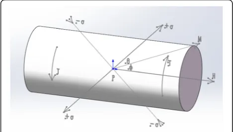
The distribution of magnetization at a point at the sur-face of a torsional circular shaft is shown in Fig.1. The
magnetic induction intensity along the axis direction can be expressed by the following formula [12–14].
B¼μ0ðHþMcosφÞ ð1Þ
B is the magnetic induction intensity along the axis direction, μ0 is the vacuum permeability, H is the
ex-ternal magnetic field, M is the magnetization, and φ is the deflection angle of the magnetization vector.
The effect of torque on the circular shaft can be equivalent to the tension or compression stress acted on the shaft with a 45° angle to the axis. The equivalent ten-sion and compresten-sion stress are proportional to the ap-plied torque, which can be expressed with the following formula:
σ¼16T
πD3; ð2Þ
whereσ is the equivalent stress,Tis the applied torque, andDis the diameter of the circular shaft.
According to the theory of magnetomechanical ef-fects [4], the stress on a circular shaft can be equiva-lent to the effective magnetic field Hσ on a circular shaft, so M is equal to the combined vector of H and Hσ. When it comes to a shaft with positive magneto-strictive effect, the direction of the magnetization vector is near the direction of the tensile stress, + σ, and away from the direction of the compressive stress, −σ, as shown in Fig.1. The offset of magnetization is in-variable under the action of constant external magnetic field. There is a thermodynamic equilibrium relationship which can be expressed with the following formula:
Ω¼U−μ0HMcos π 4−θ
−3 2σλ σð Þ
cos2θ−υsin2θ−3
2ð Þ−σ λð Þ−σ
sin2θ−υcos2θ ð3Þ
where U is the energy density produced by the inter-coupling of magnetic domains within the circular shaft, the second item is magnetostatic energy density, the last two items are the magnetic elastic coupling energy density produced by circular shaft torsion, θ is the angle between the equivalent tensile stress and the magnetization, υ is Poisson ratio, and λ(σ) repre-sents the magnetostriction produced by the uniaxial tensile stress and the external magnetic field when they are coaxial. λ(−σ) represents the magnetostriction produced by the uniaxial compressive stress and the external magnetic field when they are coaxial. λ can be expressed with the following formula:
λ¼γ1M2þγ2M4 ð4Þ
γ1 and γ2 are related to the stress, they can be
expressed with the following formula:
γ1¼γ11þγ12σ ð5Þ
γ2 ¼γ21þγ22σ ð6Þ
γ11,γ12,γ21, andγ22are constants related to the
mater-ial of the shaft.
When it comes to the shaft whose material is positive magnetostrictive, Ω increases with the increase of θ. That means the equivalent tensile stress will make the direction of magnetization close to the direction of ten-sile stress, and the equivalent compressive stress will make the direction of magnetization vector approaching to the direction of compressive stress under the constant external magnetic field. Accordingly, the equilibrium condition isdΩ/dθ= 0, and then, the following formula can be obtained.
1 ffiffiffi 2
p μ0HMðsinθ−cosθÞ þ
3
2σð1þυÞsin2θ λ σð ð Þ þλð Þ−σÞ ¼0 ð7Þ
According to θ+φ=π/4 and cos2φ= cos2φ−sin2φ, Formula (7) can be converted to a quadratic equation with one unknown whose independent variable is sinφ.
2Csin2φþ sinφ−C¼0 ð8Þ
The expression of the deflection angle of the magnetization vector φ can be obtained by solving Formula (8),
φ¼ sin−1−1þ
ffiffiffiffiffiffiffiffiffiffiffiffiffiffiffiffi 1þ8C2 p
4C ð9Þ
where C¼32 σð1þυÞ
μ0HMðλðσÞ þλð−σÞÞ. A model between the
deflection angle of the magnetization vector and the torqueThas been established, combined with the above equation.
3 Methods
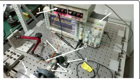
3.1 Experimental facility
The torque measurement experimental device includes a torque loading device, Hall detection circuit, shaft, oscil-loscope, DC power supply, and so on. The setup is shown in Fig.2. The material of the shaft is carbon steel, and the diameter of the shaft is 20 mm. The permanent magnet ring magnetized the shaft.
3.2 Torque loading device
The torque loading device is designed to simulate the process of the action of the torque on the drive shaft. The shaft end is fixed on the precision platform, and
the other end is connected with the flange plate used to exert torque through the bearing. The torque of the drive shaft is simulated by applying the same weight at both ends of the flange plate. This torque loading device can effectively reduce the effect of bending moment.
3.3 Non-contact signal extraction circuit
The Hall detection circuit is designed to detect the deflection angle of the magnetization vector of the magnetic iron shaft under the action of torque. The Hall circuit needs a voltage stabilizer to supply the power. In addition, the output voltage is so weak that the detection and processing of the signal are very difficult. Hence, an amplifier with high common mode rejection ratio is adopted. The amplifier can change the different magnification by adjusting the size of the adjustable resistance.
The Hall detection circuit was calibrated by the high-precision angle stage. The formula between the de-flection angle, θ, and the output voltage,V, can be ob-tained by the least square method to fit the straight line. They can be expressed by Formula (10). The maximum error value of the detection circuit is 6.97 min, and the sensitivity is 25.476 mV/min.
V¼25:476θ−10662 mVð Þ ð10Þ
3.4 Experimental process
Firstly, complete the construction of the experimental equipment, which is shown in Fig.2. Secondly, applying the same weight at both ends of the flange plate is equivalent to the torque applied to the shaft. In the ex-periment, the applied torque is 9.71 Nm, 19.02 Nm, 28.32 Nm, 37.59 Nm, 46.88 Nm, 56.13 Nm, 65.48 Nm, 74.76 Nm, 84.05 Nm, and 93.35 Nm. The torque can change the deflection angle of the magnetization vector
of the shaft, and then, the non-contact signal extraction circuit can detect the deflection angle. The deflection angle of the magnetization vector under the corre-sponding torque action can be obtained from For-mula (10). Finally, the relation between torque and the deflection angle of the magnetization vector can be obtained.
4 Results
4.1 Loading and unloading experiments
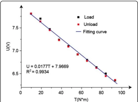
In loading and unloading experiments, torque is applied to the shaft by increasing weights, and then, the weight is reduced in turn, and each output voltage of Hall circuit is recorded. The fitting curves are drawn according to the experimental data, and the relationship between the torque and the output voltage is obtained, as shown in Fig. 3. The output voltage and torque are approximately linear both in the loading process and in the unloading process. They can be expressed by Formula (11).
V¼0:0177Tþ7:9669 ð11Þ
It means that the output voltage is proportional to the torque in the full scale. The maximum nonlinear error is 0.77% full scale, and the sensitivity is 17.7 mV/Nm.
4.2 Repeatability experiment
In the repeated experiment, the torque is constantly in-creased and the output voltage is recorded. Repeat the experiment six times. The repeatability experiment data are shown in Table1. The repeatability can be expressed by Formula (12).
s¼
ffiffiffiffiffiffiffiffiffiffiffiffiffiffiffiffiffiffiffiffiffiffi Xn
i¼1 xi−x
ð Þ2
n−1 v u u u t
ð12Þ
s is the measurement repeatability, xi is the measured data every time,xis the average, andnis the experiment times.
The data in the table shows that the maximum repeat-ability is 4.65%. The main influence factors are the phenomenon of magnetic hysteresis of the magnetized shaft in the combined action of the torque and external magnetic field.
5 Discussion
The method proposes a new idea to measure the torque. The results show that the torque is linear to the deflec-tion angle of the magnetizadeflec-tion vector. There are some ways to improve this method, which could get better re-sults and make the measurement rere-sults more accurate [15–20].
(1) Torque loading device Fig. 3The output of the torque sensor
Table 1Repeatability experiment data
Torque (Nm) First measured data (V)
Second measured data (V)
Third measured data (V)
Fourth measured data (V)
Fifth measured data (V)
Sixth measured data (V)
Repeatability (%)
9.71 7.80 7.81 7.86 7.80 7.80 7.80 2.40
19.02 7.65 7.70 7.67 7.67 7.65 7.65 1.97
28.32 7.43 7.47 7.48 7.53 7.45 7.48 3.39
37.59 7.24 7.24 7.28 7.36 7.25 7.25 4.65
46.88 7.11 7.10 7.10 7.16 7.10 7.10 2.40
56.13 6.96 6.92 6.95 7.00 6.95 6.96 2.58
65.48 6.82 6.80 6.87 6.82 6.82 6.84 2.40
74.76 6.68 6.64 6.72 6.72 6.68 6.68 3.01
84.05 6.52 6.50 6.53 6.60 6.54 6.54 3.37
The accuracy of torque provided by a torque loading device has a great impact on the experimental results. Therefore, a more precise torque loading device is needed. At the same time, the error compensation should be taken into consideration.
(2) Non-contact signal extraction circuit
The non-contact signal extraction circuit is used to de-tect the deflection angle of the magnetization vector. The measurement accuracy of the deflection angle has a great influence on the experimental results. The feed-back circuit can be designed to enhance the stability of the circuit and reduce the measurement error.
(3) Hysteresis effect
Hysteresis effect has great influence on the linearity of the system. Hysteresis on system error should be taken into consideration, and the model of torque measure-ment should be revised.
6 Conclusions
The magnetic torque sensor mostly measures the tude and explores the relationship between the ampli-tude and the torque. The torque measurement method proposed in this paper is detecting the deflection angle of the magnetization vector. The measurement of ampli-tude is easily affected by various factors, but the deflec-tion angle of the magnetizadeflec-tion vector has a strong anti-interference ability and is not easy to change. It can enhance the reliability of torque measurement and en-sure the accuracy of meaen-surement.
The model of torque measurement is derived based on the thermodynamic equilibrium. A torque loading device and a Hall detection circuit are designed to test the model. The experimental results show that the sensitiv-ity of the torque measurement system is 17.7 mV/Nm, and the maximum nonlinear error is 0.77% full scale. The experimental results verify the feasibility of this torque measurement method.
Acknowledgements
The authors would like to thank the reviewers for their thorough reviews and helpful suggestions.
Funding
This work is supported by the National Natural Science Foundation of China (Grant No 61304246).
Authors’contributions
YH is the main writer of this paper. He proposed the main idea. YY completed the experiment, analyzed the result, and finished the manuscript. XZ designed the non-contact signal extraction circuit. MZ gave some import-ant suggestions. All authors read and approved the final manuscript.
Competing interests
The authors declare that they have no competing interests.
Publisher’s Note
Springer Nature remains neutral with regard to jurisdictional claims in published maps and institutional affiliations.
Received: 10 February 2018 Accepted: 18 September 2018
References
1. Y.L. Zheng, H.Y. Lu, W. Yin, D.S. Tao, L.C. Shi, Y. Tian, Elegant shadow making tiny force visible for water-walking arthropods and updated Archimedes’ principle. Langmuir32, 10522–10528 (2016)
2. Y. Zheng, L. Song, G. Hu, et al., The multi-position calibration of the stiffness for atomic-force microscope cantilevers based on vibration. Meas. Sci. Technol.26(5), 055001 (2015)
3. G. Zhang, G. Xie, L. Si, S. Wen, D. Guo, Ultra-low friction self-lubricating nanocomposites with mesoporous metal-organic frameworks as smart nanocontainer for lubricants. ACS Appl. Mater. Interfaces9, 38146–38152 (2017)
4. J. Li, J. Luo, Nonlinear frictional energy dissipation between silica-adsorbed surfactant micelles. J. Phys. Chem. Lett.8, 2258–2262 (2017)
5. C. Dong, C. Yuan, X. Bai, J. Li, H. Qin, X. Yan, Coupling mechanism between wear and corrosion processes of 304 stainless steel in hydrogen peroxide environments. Sci. Rep.7, 2327 (2017)
6. H. Zhao, Present situation and development review of torque measurement. Appl. Mech. Mater.422(422), 141–145 (2013)
7. S.P. Chen,Research on ring type torque sensor based on magnetoelastic effect of amorphous alloy(China, China University of Mining and Technology, 2016) (in Chinese)
8. R. Meng, H.Q. Wang, Signal acquisition and processing of non-contact torque sensor for vehicle. Control Eng. China.19(2),157-160 (2012) 9. H. Muro, C. Saito, M. Shimada, et al., inSensors. Magnetostrictive-ring type
torque sensor using two Hall ICs with differential magnetic field detection (IEEE, 2014), pp. 412–415
10. D.C. Jiles, Theory of the magnetomechanical effect. J. Phys. D Appl. Phys.
28(8), 1537 (1995)
11. M.J. Sablik, D.C. Jiles, Modeling effects of varying torsion in magnetized steel. IEEE Trans. Magn.36(5), 3248–3250 (2002)
12. O.M. Vasilevskyi, Metrological characteristics of the torque measurement of electric motors. Int. J. Metrol. Qual. Eng.8(7), 9 (2017)
13. Y.L. Guo, Z.F. Chang, N.A. Shao-Dan, Magnetic field and output voltage analysis of 3D torque sensor. Transducer Microsyst. Technol.36(2),18-20 (2017) 14. J.C.S. Borges, D.B.B.D. Deus, A.C.L. Filho, et al., New contactless torque sensor
based on the Hall effect. IEEE Sensors J.PP(99), 1 (2017)
15. K.C. Min, J.Y. Choi, S.Y. Sung, et al., Torque analysis of magnetic spur gear with radial magnetized permanent magnets based on analytical method. Trans. Korean Inst. Electr. Eng.64(4), 545–551 (2015)
16. Q. Liang, X. Cheng, S.C.H. Huang, et al., Radar and sonar sensor networks. EURASIP J. Wirel. Commun. Netw.2010(1), 948604 (2010)
17. Q. Liang, Radar sensor networks: algorithms for waveform design and diversity with application to ATR with delay-doppler uncertainty. EURASIP J. Wirel. Commun. Netw.2007(1), 1–9 (2007)
18. Q. Liang, Biologically inspired target recognition in radar sensor networks. EURASIP J. Wirel. Commun. Netw.2009(1), 1–8 (2010)