R E S E A R C H
Open Access
Dynamic configuration management of a
multi-standard and multi-mode reconfigurable
multi-ASIP architecture for turbo decoding
Vianney Lapotre
1*, Guy Gogniat
1, Amer Baghdadi
2and Jean-Philippe Diguet
1Abstract
The multiplication of connected devices goes along with a large variety of applications and traffic types needing diverse requirements. Accompanying this connectivity evolution, the last years have seen considerable evolutions of wireless communication standards in the domain of mobile telephone networks, local/wide wireless area networks, and Digital Video Broadcasting (DVB). In this context, intensive research has been conducted to provide flexible turbo decoder targeting high throughput, multi-mode, multi-standard, and power consumption efficiency. However, flexible turbo decoder implementations have not often considered dynamic reconfiguration issues in this context that requires high speed configuration switching. Starting from this assessment, this paper proposes the first solution that allows frame-by-frame run-time configuration management of a multi-processor turbo decoder without
compromising the decoding performances.
Keywords: Wireless communication, Turbo codes, ASIP, Dynamic configuration
1 Introduction
The last years have seen considerable evolutions of wireless communication standards in the domain of mobile telephone networks, local/wide wireless area net-works, and Digital Video Broadcasting (DVB). Besides the increasing requirements in terms of throughput and robustness against destructive channel effects, the con-vergence of services in single smart terminal becomes a crucial and challenging feature. Channel coding is a key technique of a wireless communication standard. It allows reliable data transfer targeting high throughput over unre-liable communication channels. A channel coding tech-nique is typically associated to a variety of parameters and configuration options (frame size, communication chan-nel, signal-to-noise ratio, etc.). Among channel coding techniques, turbo codes [1] are frequently adopted in the recent wireless standards to reach a very low bit error rate (BER).
*Correspondence: [email protected]
1Laboratoire Lab-STICC - CNRS, UMR 6285, Centre de Recherche Christiaan
Huygens, Rue de Saint-Maudé - BP 92116, 56321 Lorient, France Full list of author information is available at the end of the article
The introduction of contention-free interleavers in recent communication standards, such as long-term evolution (LTE) [2] and Worldwide Interoperability for Microwave Access (WiMAX) [3], enables high-throughput implementations such as presented in [4–8] and [9]. These architectures propose to use multi-ple soft-input soft-output (SISO) decoders to reach the high throughput requirement of emerging and future standards. They offer certain degrees of flexibility to adapt for instance the number of SISO decoders, the turbo code mode, i.e., single binary turbo code (SBTC) or double binary turbo code (DBTC), or the frame size. However, these efforts do not present any configuration infrastructure in order to support a fast and efficient dynamic configuration switching. In [10], the authors propose a solution in order to support dynamic config-uration. They present an field-programmable gate array (FPGA) implementation of a high speed MAP decoder architecture for turbo decoding achieving 346 Mbps. The configuration latency cost of such an implementation is not evaluated. The configuration latency of Xilinx FPGA [11] depends on the targeted FPGA technology, the bitstream size and the medium used to transfer the con-figuration bitstream. However, the concon-figuration latency
overhead is still important (from around 100μs to 100 ms [11]). Recent work investigated general purpose pro-cessor (GPP) implementations using high-performance multi-core architectures taking advantage of the Intel SSE (Streaming SIMD Extensions) instructions. In [12], a 418 Mbps turbo decoder for LTE is implemented on an Intel Xeon processor X5670 with a 12 threads level of parallelism. In [13], an adaptive turbo decoder imple-mentation on an Intel I7-960 core is investigated. The authors propose to adapt the decoding algorithm depend-ing on the communication channel quality. However, for both [12] and [13] works, no discussion is provided about the context switching cost when the turbo decoder configuration has to be changed. Moreover, these GPP implementations have been initially developed for base stations. Thus, they are not suitable for mobile terminals due to the high power consumption of such processors.
Recently, application-specific instruction-set proces-sor (ASIP) solutions have been investigated in order to offer architectures providing good trade-offs in terms of flexibility, throughput and power dissipation. In [14], a flexible and high performance ASIP model for turbo decoding was proposed, which can be config-ured to support all simple and double binary turbo codes up to eight states. The architecture uses shuf-fled decoding with frame sub-blocking. The extrinsic information is iteratively and concurrently exchanged between multiple component decoders via an on-chip communication network presented in [15]. Afterwards, an optimized implementation of the ASIP supporting both turbo codes and LDPC codes, called DecASIP have been presented in [16]. Similarly, the authors in [17] introduce the FlexiTreP ASIP presented in [18] in a multi-ASIP architecture for turbo decoding to reach the 150 Mbps throughput requirement of LTE. Previous works provide an efficient way to reach the high per-formance requirement of emerging standards. However, the dynamic reconfiguration aspect of these platforms is superficially addressed. In [19], the authors propose a reconfigurable multi-processor approach in order to decode multiple data streams in parallel. However, the timing impact of such a reconfiguration process is not detailed. Among the few works which consider this issue, we can cite the recent architecture presented in [20], where the authors propose solutions for the reconfigu-ration management of the network-on-chip (NoC) based multi-processor turbo/LDPC decoder architecture pre-sented in [21]. Up to 35 processing elements (PEs) and up to 8 configuration buses have been implemented. Each PE is configured through a configuration memory, which is organized as a circular buffer. The reconfigura-tion process to switch from one configurareconfigura-tion to another configuration can be masked by the current decod-ing task if the configuration memory provides enough
free space and if a high speed configuration infrastruc-ture is provided. Dynamic reconfiguration during one frame duration is possible when the current configu-ration is small enough to load a new configuconfigu-ration in the memory. If not, the authors provide management solutions to deal with this issue, such as erasing the current configuration during the last decoding itera-tion and continuing the reconfiguraitera-tion process during the first iteration of the new configuration. However, this solution is not always sufficient. Then, stopping the current processing to configure the new configu-ration is unavoidable and leads to a decoding quality loss in terms of BER. The authors of [22] propose a dynamically reconfigurable ASIP-based architecture for turbo decoding allowing reconfiguration of the entire platform during the current decoding task in order to propose a frame by frame dynamic configuration. This architecture has been optimized based on the ini-tial work presented in [16]. Up to 64 processors are reconfigured using a bus-based configuration infrastruc-ture implementing optimized transfer mechanisms. In this context, this paper aims to bring a complete config-uration management solution for multi-processor turbo decoder providing novel solutions allowing for the first time: (1) a run-time evaluation of the number of decoding iterations and the level of sub-block parallelism regard-ing throughput and bit error rate (BER) requirements and (2) a run-time configuration generation. As a base architecture, the reconfigurable UDec ASIP-based turbo decoder presented in [22] is considered. Therefore, the corresponding architectural parameters in terms of mem-ory bank sizes and communication interfaces between the ASIPs have been used. In this paper, no specific optimiza-tions have been introduced regarding the turbo decoding itself.
The rest of this paper is organized as follows. Section 2 gives more insights about the motivation of this work. Section 3 provides basics about turbo decoding and related parallelism techniques. Section 4 introduces the Reconfigurable UDec architecture implementing the RDecASIP processor. Section 5 presents the proposed method to dynamically evaluate the number of decod-ing iterations and the level of sub-block parallelism that have to be used to reach throughput and BER objectives. Section 6 describes the proposed configuration manage-ment method and evaluates the obtained performances. Finally, Section 7 concludes the paper.
2 Motivation
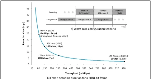
presented in Fig. 1a is considered as the worst-case config-uration scenario that should be met by a multi-mode and multi-standard turbo decoder in mobility.
In future systems simultaneous applications dealing with multiple communications standards have to be considered. In this scenario, the turbo decoder deals with input frames that have to be decoded for multiple applications that use different communication standards or modes. Each application is associated with specific throughput and BER objectives. Moreover, considering a mobile terminal, the configuration associated to an appli-cation has to be adapted temporally depending on the communication channel quality evolution. Consequently, as shown in Fig. 1a, each frame received by the turbo decoder is associated to a specific configuration, which takes into account the application requirements and the channel quality. In order to avoid extra delays between two frames associated with different configurations, the configuration process for a frame (i.e., computing and loading the new configuration) can be performed during the processing of the current frame. Thus, the maximum configuration latency (MCL) for a framekensuring a null extra delay between two frames is evaluated using (1).
MCL(k)=NPrevFrame(k).
FrameSize(k−1).Rc(k−1) Throughput(k−1) (1) wherekis thekth received frame,NPrevFrame is the num-ber of consecutive frames decoded with the same con-figuration that precedes the framek, FrameSize(k − 1)
is the (k − 1)th frame size in bits, Throughput(k −
1) is the throughput requirement associated with the
(k − 1)th data frame and Rc(k − 1) is the code rate associated with(k−1)th data frame. MCL, FrameSize, and Throughput are expressed in seconds, bits, and bits/s, respectively. Assuming the worst case when
NPrevFrame(k) = 1, the maximum configuration latency critically decreases with high throughput targeted by emerging and future wireless communication stan-dards as shown in Fig. 1b. This figure presents the decoding latency, i.e., frame duration in Fig. 1b., of a 2048-bit data frame for different wireless communi-cation standards. Regarding the throughput requirement evolution, the decoding latency of a frame decreases and will reach latencies around few microseconds in LTE-advanced standard. Thus, considering the dynamic configuration scenario presented in this section, emerg-ing and future high-throughput mode and multi-standard architectures will have to deal with maximum configuration latencies around few microseconds. That is why, this paper presents solutions to solve this challenging issue.
3 Turbo decoding
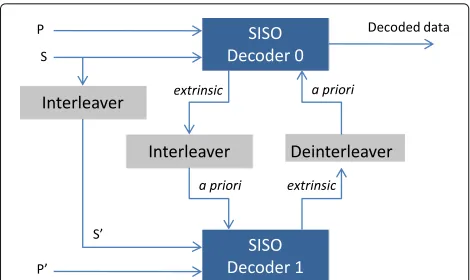
Turbo decoding principle is based on an exchange of prob-abilistic information, calledextrinsic informationbetween two (or more) component decoders dealing with the same received set of data. As shown in Fig. 2, a typical turbo decoder consists of two decoders operating iteratively on
Fig. 2Typical turbo decoder structure
the received frame. The first component (SISO decoder 0 in Fig. 2) works in natural domain while the second (SISO decoder 1 in Fig. 2) works in interleaved domain. The soft-input soft-output (SISO) decoders operate on soft information to improve the decoding performance. Thus, besides its own channel input data, each SISO decoder deals with the extrinsic information generated by the other SISO decoder in order to improve its estimation over the iterations. Usually, but not necessary, the compu-tations are done in the logarithmic domain. Each decoder calculates the log-likelihood ratio (LLR) for theith data bit
dias
L(di) = lnPr(di=1|y) Pr(di=0|y)
(2)
Input LLRs causing trellis transition can be decomposed into three independent terms as
L(di) = Lapr(di)+Lsys(di)+Lpar(di) (3) where Lapr(di) is the a-priori information of d
i,Lsys(di)
andLpar(di)are the channel measurement of the system-atic and parity parts respectively. Each input soft-output (SISO) decoder generates extrinsic information that is sent to the other decoder. Extrinsic information becomes the a-priori information Lap(di) for the other decoder as shown in Fig. 2.
Several algorithms for this SISO decoding have been proposed in the literature. The soft output Viterbi algo-rithm (SOVA) and the Maximum Aposteriori Probability (MAP) algorithms are the most frequently used. This last algorithm has been simplified in [23] to propose the Max-Log-MAP algorithm that is most often adopted because of the efficient hardware implementation possibility. For a better understanding of the architectural and config-uration issues highlighted in the rest of this paper, the next sub-section provides a short introduction to the Max-Log-MAP decoding.
3.1 Max-Log-MAP algorithm
In order to explain briefly the underlined computations, let us consider the 8-state double binary turbo code (DBTC) of WiMAX standard. For each received dou-ble binary symbol (S0,S1)k, the SISO decoder computes
first the branch metrics (γk(s,s)) which represent the probability of a transition to occur between two trellis states (s, starting state; s, ending state). These branch metrics can be decomposed, as defined by the following expressions, in an intrinsic part (γintrx
k (s,s)) due to the
systematic information (γsysx
k (s,s)), the a-priori
informa-of thekth symbol or the normalized extrinsic information (Zkn.ext), sent by the other decoder component (expression given below). Furthermore, the systematic and the parity information in these expressions represent thesymbol log-likelihood-ratios (LLRs) which can be obtained by direct addition and subtraction operations between the received channelbitLLRs (S0, S1, P0, P1, P0, P1).
Then the SISO decoder runs the forward and backward recursion over the trellis. The forward state metricsαk(s)
of thekth symbol are computed recursively using those of the (k− 1)th symbol and the branch metrics of the corresponding trellis section. Similarly for the backward state metrics βk(s) which correspond to the backward recursion (traversing the trellis in the reverse direction).
αk(s)=max
Finally, the extrinsic information of the kth symbol is computed for all possible decisions (00, 01, 10, 11)using the forward state metrics, the backward state metrics, and the extrinsic part of the branch metrics as formulated in the following expressions:
Zaposk (d(s,s)=x)= max
(s,s)/d(s,s)=x(αk−1(s)+γk(s
Zextk (d(s,s)=x)=Zkapos(d(s,s)=x)−γintx k (s,s)
∀(x=00, 01, 10, 11) (9)
The extrinsic information can be normalized by sub-tracting the minimum value in order to reduce the related storage and communication requirements; thus, only three extrinsic information values should be exchanged for each symbol.
Zkn.ext(d(s,s)=x)=Zextk (d(s,s)=x)−min(Zkext(d(s,s)=x))
∀(x=00, 01, 10, 11) (10)
Executing one forward-backward recursion on all sym-bols of the received frame in the natural order completes one half iteration. A second half iteration should be exe-cuted in the interleaved order to complete one full turbo decoding iteration. Once all the iterations are completed (usually 6–7 iterations), the turbo decoder produces a hard decision for each symbolZkhard dec.∈(00, 01, 10, 11).
For SBTC, the use of the trellis compression (radix-4) [24] represents an efficient parallelism technique and allows or efficient resource sharing with a DBTC SISO decoder as two single binary trellis sections (two bits) can be merged into one double binary trellis section.
The next section introduces the different levels of paral-lelism that can be exploited considering a Max-Log-MAP SISO decoder. It particularly highlights the SISO decoder level parallelism.
3.2 Parallelism in turbo decoding
Turbo decoding provides an efficient solution to reach very low error rate performance at the cost of high processing time for data retrieval. In order to face this limitation, many efforts targeting the exploitation of par-allelism have been conduced in order to achieve high throughput. These parallelism levels can be categorized in three groups: metric level, SISO decoder level, and turbo decoder level.
The metric level parallelism deals with the processing of all metrics involved in the decoding of each received symbol inside a Max-Log-MAP SISO decoder. For that purpose, the inherent parallelism of the trellis structure [25, 26] and the parallelism of the MAP computation can be exploited [25–27]. The SISO decoder level paral-lelism consists in duplicating the SISO decoders in natural and interleaved domains, each executing the MAP algo-rithm on a sub-block of the frame to be decoded. Finally, the turbo decoder level parallelism proposes to dupli-cate whole turbo decoders to process iterations and/or frames in parallel. However, this level of parallelism is
not relevant due to the huge area overhead of such an approach (all memories and computation resources are duplicated). Moreover, this solution presents no gain in frame decoding latency.
The SISO decoder level parallelism hugely impacts the configuration process of a multi-processor turbo decoder. Indeed, the number of SISO decoders that have to be con-figured and the configuration parameters associated with each SISO decoder are both dependent of this parallelism level. At this level, two techniques are available: frame sub-blocking and shuffled decoding. These two techniques are detailed in the hereafter.
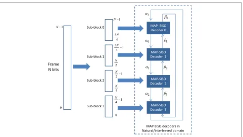
Frame sub-blocking: In sub-block parallelism, each frame is divided into Mblocks and then each sub-block is processed on a Max-Log-MAP SISO decoder (Fig. 3). Besides duplications of Max-Log-MAP SISO decoders, this parallelism imposes two other constraints. On the one hand, interleaving has to be parallelized in order to proportionally scale the communication band-width. Due to the scramble property of interleavers, this parallelism can induce communication conflicts except for interleavers of emerging standards that are conflict-free for certain parallelism degrees. In case of conflicts, an appropriate communication structure, e.g., NoC, should be implemented for conflict management [15]. On the other hand, Max-Log-MAP SISO decoders have to be ini-tialized adequately either by acquisition or by message passing (βi andαi on Fig. 3). In [28], a detailed analysis of the parallelism efficiency of these two methods is pre-sented. It gives favor to the use of the message passing technique. The message passing, which initializes a sub-block with recursion metrics (α and β) computed dur-ing the previous iteration in the neighbordur-ing sub-blocks (Fig. 3), presents negligible time overhead compared to the acquisition method.
Fig. 3Sub-block parallelism with message passing for recursion metric initialization
Frame sub-blocking and shuffled turbo decoding greatly impact the number of SISO decoders that have to be configured for a given throughput objective. Thus, the configuration load and the configuration latency depend on these two techniques. Moreover, these levels of par-allelism impact the performance of the decoder. Thus, it directly impacts the number of decoding iterations that has to be performed for a given BER objective [30]. This section has provided the basic background on turbo decoding and on the different levels of parallelism which can be exploited in order to reach high-throughput requirement imposed by emerging communication stan-dards. The next section introduces the reconfigurable multi-ASIP UDec architecture for turbo decoding.
4 Reconfigurable UDec architecture
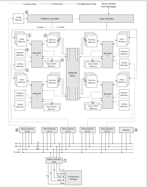
The dynamically reconfigurable UDec architecture con-sidered in this work is shown in Fig. 4. It consists of two columns of RDecASIP processors interconnected via two unidirectional Butterfly networks-on-chip supporting shuffled turbo decoding. Each column corresponds to a component decoder, one processing the data in natural domain and the other in interleaved domain. In the exam-ple of Fig. 4, four ASIPs are organized in two component decoders built with two ASIPs, respectively. Each RDe-cASIP is associated with three input memory banks of size 24×256 used to store the input channel LLR values①.
There are also three banks of size 30×256 used for extrin-sic information storing②. Each ASIP is further equipped with two 88×32 memories which hold state metric values ③and a read-only program memory④which contains the instructions in order to perform the decoding algorithm. Moreover, each ASIP is configured through a configura-tion memory ⑤which contains all parameters required to perform the initialization of the ASIP. Finally, the con-figurable platform controller⑥manages the initialization, configuration, and decoding processes. It is worth not-ing that in the complete receiver architecture, the input memories of the turbo decoder are duplicated to allow buffering of next input streaming frame from the demap-per while executing the iterative turbo decoding on the current received frame. However, this buffering part is not critical as the real timing constraint will be imposed by the iterative decoding process.
an interface allowing the connection of the configuration manager to the bus, the SI provides an interface between the bus and the configuration memory, and the Selec-tor provides a simple and efficient solution to select, at run-time, RDecASIPs that are targeted by the next con-figuration data. For clarity reasons, connections between the Selector and the SIs are not represented in Fig. 4. This infrastructure allows the transfer of a data into the RDecASIP configuration memory in 5 clock cycles. More details on the UDec configuration infrastructure architec-ture and implementation can be found in [22, 31].
The RDecASIP [32, 33] implements the Max-Log MAP algorithm (Sub-section 3.1) for LTE, WiMAX, and DVB-RCS standards. It supports both single and double binary convolutional turbo codes and implements radix-4 trellis compression technique for SBTC mode. Moreover, slid-ing window technique [34, 35] is used. Large frames are processed by dividing the frame intoNw windows each
with a maximum size of 64 symbols. Each ASIP can man-age a maximum of 12 windows. Since the RDecASIP is designed to work in a multi-ASIP architecture, it requires several parameters to deal with a sub-block of the data frame and several parameters to configure the ASIP mode. Concerning the sub-block partitioning, each ASIP is con-figured with the size and the number of windows it has to decode. Furthermore, the last window size can be dif-ferent, so it corresponds to an additional parameter. In a SBTC decoding mode, the address of the tail bits in memory, the size, and the number of windows for the spe-cific decoding phase of the tail bits have to be configured. Parameters for the ASIP mode correspond to the loca-tion of the ASIP in the architecture, the number of ASIPs required, the parameter which defines if the current ASIP is in charge of tail bits or not, the target standard, and the scaling factor for extrinsic information. Finally, some seed values are necessary for interleaving address gen-eration in order to exchange information over the NoC that connects the ASIPs of each decoder component. All these parameters are required for each new configura-tion of an ASIP within the platform and are stored in a configuration memory (⑤in Fig. 4). This configuration load represents 253 bits per ASIP. Thus, at run-time, all these parameters need to be computed and loaded into the configuration memories when a new configuration is required. For optimizing the configuration latency, the configuration memory has been organized in a way that allows broacasting and multi-casting transfers [32, 33]. In this context, the configuration latency of the UDec plat-form using the proposed configuration infrastructure is defined by (11) [31].
ConfigurationLatency = 31+(3.NASIP)
Fclk
(11)
WhereNASIP is the number of RDecASIPs andFclk is the frequency of the proposed bus architecture. Thirty-one clock cycles are necessary to transfer the parameters common to all ASIPs (broadcasting) and the parameters common to ASIPs of the same decoder component (multi-casting). Three additional clock cycles are necessary to transfer parameters that are different for each ASIP.
In order to define the number of ASIPs that needs to be reconfigured to meet the throughput requirement, (12) can be used. It gives the throughput reached by the UDec architecture regarding the number of RDecASIP selected to perform the decoding task. An average of Ninstr = 4 instructions per iteration are needed to process one symbol which is composed of two bits.
Throughput= Fclk×(NASIP/2)
Ninstr×Niter
(12)
where Fclk and Niter are the clock frequency of the sys-tem and the number of decoding iterations respectively.
(NASIP/2)reflects the level of sub-block parallelism. This throughput is multiplied by two when shuffled decoding is enabled. The decoding latency is dictated by the process-ing latency of the RDecASIPs. In the complete receiver architecture, input memories of the turbo decoder are duplicated to allow buffering of next input streaming frame from the demapper while executing the iterative turbo decoding on the current received frame. Similarly, the Butterfly NoCs are dimensioned to accommodate the required communication bandwidth dictated by the RDe-cASIPs. Therefore, regarding the RDecASIPs latency, 4 clock cycles (i.e. 4 instructions) are needed to process 1 symbol which is composed of 2 bits. This latency should be multiplied by the number of iterations and the number of symbols in a frame (FrameSize/2). On the other side, it should be divided by the number of ASIPs per com-ponent decoder (NASIP/2). Finally, 10 clock cycles should be added once due to the 10 pipeline stages of the ASIP [32, 33].
DecodingLatency = Ninstr×Niter×(FrameSize/2)
Fclk×(NASIP/2) + 10
(13)
5 Dynamic estimation of the number of decoding iterations for turbo decoding
This section analyses the impact of sub-block parallelism regarding the number of decoding iterations, which have to be performed with respect to a given FER (Frame Error Rate) or BER. Then, a low-complexity method to dynamically estimate the number of decoding iterations with respect to the level of sub-block parallelism, which is suitable for run-time execution, is proposed.
5.1 Case of sub-block parallelism
In the context of this work considering the Reconfigurable UDec architecture presented in Section 4, sub-block par-allelism method is associated with initialization by mes-sage passing as described in Sub-section 3.2. This method dynamically initializes a sub-block with recursion met-rics computed during the last decoding iteration in the neighboring sub-blocks. The authors of [28] have studied the impact of sub-blocking on the turbo decoding per-formance in terms of FER considering message passing and conclude that asymptotic error rate is not affected by message passing approach whatever is the parallelism degree. Thus, it ensures that initialization by message passing can be used without performance degradation in terms of decoding quality by increasing the number of decoding iterations with respect to the level of sub-block parallelism.
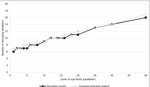
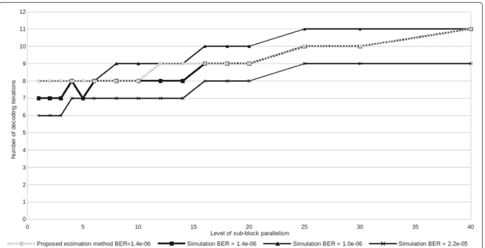
In order to study the dynamic evolution of the num-ber of decoding iterations w.r.t., the level of sub-block parallelism, intensive simulations have been performed. Simulation results are shown in dark straight line in Figs. 5 and 6 for two configurations. The configuration in Fig. 5 presents the case of a communication with good SNR channel condition targeting a very low BER equals to 6.6×10⁻⁶while the configuration presented in Fig. 6 presents the case of a communication with low SNR. The results of the different conducted simulations show that the necessary number of iterations can be roughly esti-mated using a simple equation taking into account a base number of decoding iterations, the level of sub-block par-allelism, and a threshold value that drives the evolution of the number of decoding iterations that have to be per-formed to reach the target BER. The number of necessary decoding iterations is given by (14).
Niter = NiterBase+
P
T (14)
whereNiterBaseis the number of decoding iterations that has to be performed when the level of sub-block par-allelism is one for a fixed target BER, T is a constant threshold that can be evaluated by studying the linear behavior of the evolution of the number of decoding iter-ations, andPrepresents the level of sub-block parallelism that have to be used to reach a given throughput. Thus,
Fig. 6Number of iterations with message passing method, WiMAX, Max-Log MAP, code rate = 2/3, 1920 bits frame, SNR = 2.3 dB
NiterBase andT are determined by analyzing the simula-tion results. In our experiments,NiterBase has been fixed using one additional iteration in order to provide a BER greater or equal to the original BER objective. In the examples of Figs. 5 and 6, NiterBase is equal to 7 and 8, respectively.T values have been estimated by analyzing the slope of the curve created with the simulation results shown in straight dark line in Figs. 5 and 6. In Figs. 5 and 6, T is equal to 4 and 11, respectively. It is worth noting that, regarding a given configuration, the value of T is constant whatever is the target BER for typical
NiterBasevalues (from 5 to 10). Indeed, the degradation of the decoding quality due to the increasing level of sub-block parallelism is independent of the targeted BER. It is related to the message passing method used for Max-Log-MAP SISO decoders initialization. This observation is illustrated in Fig. 6 where the behavior for three dif-ferent BER objectives is shown. Indeed, we observe that the slope of the curves is roughly identical allowing an estimation with a unique value T for a fixed SNR. Esti-mation results using (14) are presented in gray dotted line in Figs. 5 and 6. Results show that, (14) provides a low complexity solution that can be easily implemented on a mobile device to estimate the number of neces-sary decoding iterations with at most one more decoding iteration compared to the simulation results. It is worth noting that when the number of estimated decoding iter-ations is not equal to that obtained through simuliter-ations, it is overestimated ensuring the decoding performance in terms of BER.
5.2 Case of shuffled decoding
The work presented in [30] shows that when using shuffled decoding, the number of decoding iterations is slightly increased compared to the number of decoding iterations required to reach the same error rate perfor-mance when using serial decoding. For example, in [30], the authors study the shuffled decoding parallelism effi-ciency (i.e., decoding performance in terms of FER) using the interleaving rules specified in WiMAX/DVB-RCS. Tables 1 and 2 show that the number of decoding itera-tions guaranteeing the same decoding performance has to be increased when shuffled decoding is used. It is worth noting that the shuffled decoding efficiency is higher than 0.5 for all configurations presented in Tables 1 and 2. This means that despite of the increasing number of decod-ing iterations, the shuffled decoddecod-ing still provides higher throughput than serial decoding. Moreover, it can be
Table 1Comparison of necessary number of decoding iterations regarding the level of sub-block parallelism for 53 bytes DVB-RCS interleaving code rate = 6/7, SNR = 4.0 dB, Log-MAP algorithm, FER = 1.6×10⁻³
Sub-block parallelism
Number of iterations without shuffled decoding
Number of iterations with shuffled decoding
Shuffled decoding efficiency
1 8 12 0.66
4 11 15 0.73
8 16 20 0.8
Table 2Comparison of necessary number of decoding iterations regarding the level of sub-block parallelism for 188 bytes DVB-RCS interleaving code rate = 6/7, SNR = 4.0 dB, Log-MAP algorithm, FER = 1.6×10⁻³
highlighted that the shuffled decoding efficiency increases when the level of sub-block parallelism increases too. This leads to a relative constant number of additional decoding iterations when shuffled decoding is enabled, i.e., four in Table 1 and between two and four in Table 2. Thus, when shuffled decoding is used, (14) can be modified as follows:
Niter = NiterBase+ whereNiterShuffledis a constant that depends of the consid-ered standard and frame size.
In the next subsection, the proposed estimation method is considered for the configuration process of the recon-figurable UDec architecture. An algorithm jointly deter-mining the number of decoding iterations and the level of sub-block parallelism is proposed to be used at run-time in order to dynamically generate the configuration data for the reconfigurable UDec platform.
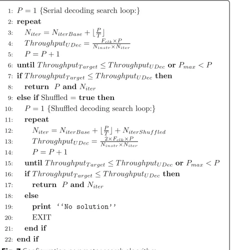
5.3 Configuration parameters search algorithm
Before generating the configuration data for each RDe-cASIP configuration memory, the level of sub-block par-allelism and the number of decoding iterations to reach the target throughput and the target BER has to be deter-mined. For that purpose, the algorithm presented in Fig. 7 is proposed. It requires the following inputs: (1) the frame size and the target throughput, (2) the base number of decoding iterations NiterBase and the threshold value T, which are used to compute the necessary number of decoding iterations as explained in the two previous sub-sections, and (3) Pmax, which is the maximum level of sub-block parallelism supported by the platform. While the frame size and the target throughput are transfered to the UDec platform at run-time, the base number of decoding iterations NiterBase and the threshold value T taking into account different SNR and BER objectives have to be stored in a memory associated to the configuration manager. Each couple of values (NiterBase,T) can be stored using 2 bytes. Thus, the number of bytes necessary to store
Fig. 7Configuration parameter search algorithm
these parameters can be determined using the following equation:
Nbytes = NSNR×NBER×2 (16) WhereNSNR andNBER represent the number of sup-ported SNR and BER objectives, respectively.
algorithm favors a serial decoding configuration since it requires less decoding iterations as shown in Tables 1 and 2. If shuffled decoding cannot be used, the recon-figurable UDec architecture is not able to support such a configuration respecting the required decoding perfor-mance. In this case, a default configuration respecting either the target throughput or the BER objective can be generated. However, the system should be dimensioned at design-time to support the worst-case supported sce-nario. It is worth noting that the proposed algorithm does not provide an optimum solution. Indeed, the algorithm stops when the first solution is found. Thus, it guarantees that, for a given configuration, the minimum number of RDecASIPs is used. However, for a given configuration, more RDecASIPs could be used for decoding a frame in a shorter time (i.e., by increasing the throughput of the platform).
The next section presents the proposed configuration management solution ensuring a frame-by-frame config-uration process, as the worst-case configconfig-uration scenario, as presented in Section 2.
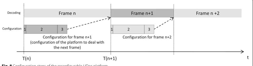
6 Run-time configuration management
In the context of this work, the maximum configuration latency of a frame is constrained by the previous frame decoding duration as illustrated in Section 2. The config-uration of the reconfigurable UDec architecture is divided in three steps as shown in Fig. 8:
1. The configuration manager (shown in Fig. 4) receives the configuration order associated with the frame parameters (i.e., frame size, standard, throughput, and targeted BER) necessary to generate the configuration for the RDecASIPs.
2. The configuration manager generates the
configuration parameters for each selected RDecASIP configuration memory presented in Section 4. 3. The configuration parameters for each selected
RDecASIP are transfered through the configuration infrastructure presented in Section 4.
For this study, we assume that the configuration man-ager generates at run-time the configuration information for the entire UDec architecture based on the configu-ration parameters received with the configuconfigu-ration order for the next frame. These parameters are the frame size, the throughput requirement, the target standard, and the BER objectives which are used to compute the number of decoding iterations as explained in Section 5. From these parameters, the number of activated RDecASIPs is first determined depending on the number of decoding itera-tions using the search algorithm presented in Fig. 7. Then, the contents of the different configuration memories of the reconfigurable UDec architecture can be generated.
In the context of the multi-mode and multi-standard scenario, where the configuration latency for the next frame is limited by the decoding duration of the current frame, the minimum decoding duration respecting this rule can be deduced from the maximum configuration latency of the platform which is reached when all the RDe-cASIPs processors have to be configured. It guarantees that the configuration latency is lower than the decoding duration whatever is the configuration which has to be performed. Thus, the maximum achievable throughput is theoretically limited for a given frame size and is given by (17) where Frame durationmin is equal to the maxi-mal configuration generation latency plus the maximaxi-mal configuration transfer latency.
Thmax(in bps) =
Frame size(in bits) Frame durationmin(ins)
(17)
In order to estimate the configuration generation latency of the reconfigurable UDec architecture, a C-code allowing a run-time configuration generation has been implemented on an ARM cortex A15 core with a fre-quency of 1600 MHz. It is important to note that the considered C-code has not been fully optimized and not parallelized. This C-code consists in two steps. The first step is an implementation of the algorithm shown in Fig. 7 to determine the number of decoding iterations that have to be performed and the level of sub-block parallelism
Table 3Configuration transfer latency in nanosecond for different levels of sub-block parallelism
Level of sub-block
for a given configuration. The second step generates the configuration data for each configuration memory of the UDec architecture. Implementation results show that the configuration generation latency for a maximum level of sub-block parallelism of 32 (64 RDecASIPs) is 4.14 μs. The first step requires 1.44μs while the second step requires 2.7μs in order to generate 18,590 configuration bits that have to be loaded in the 64 RDecASIPs con-figuration memories and in the platform concon-figuration memory.
The different configuration memories are filled through a configuration infrastructure shown in Fig. 4. In order to compute the configuration transfer latency using (11), it is necessary to fix the frequency of the configuration infrastructure. For that purpose, a logic synthesis of the configuration infrastructure was successfully performed targeting a 65 nm CMOS technology with a clock fre-quency objective equals to 500 MHz. This frefre-quency has been chosen in regard to RDecASIP maximum clock fre-quency [31]. Table 3 presents the configuration transfer latencies for various levels of sub-block parallelism. The maximum configuration transfer latency for a level of sub-block parallelism equals to 32 is 446 ns.
Consequently, the maximum total configuration latency of the reconfigurable UDec architecture implementing
Table 4Maximum throughput of the reconfigurable UDec platform with 64 RDecASIPs,Ninstr = 4,Fclk = 500 MHz
Number of decoding iterations Max. throughput (in Mbps)
Serial decoding Shuffled decoding
Table 5Maximum throughput supporting frame-by-frame configuration scenario in serial decoding with 64 RDecASIPs,
Ninstr = 4,Fclk = 500 MHz
Frame size Max. throughput (in Mbps)
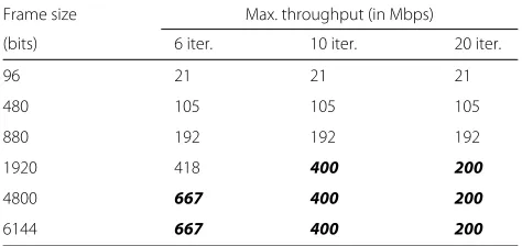
(bits) 6 iter. 10 iter. 20 iter.
96 21 21 21
64 RDecASIPs is 4.586μs. This maximum configuration latency represents the latency to generate a configuration for 64 RDecASIPs plus the latency to send the configura-tion data into the configuraconfigura-tion memories of the platform. Considering this maximum configuration latency, a max-imum theoretical throughput ensuring the configuration constraints described in Section 2 for a given frame size can be determined using (17). However, this maximal throughput is limited by the number of decoding itera-tions and the number of implemented RDecASIPs in the platform. Table 4 shows the maximal throughput consid-ering the number of decoding iterations and the decoding mode. These results are obtained from (12) considering 64 RDecASIP.
Based on the results presented in Table 4 and consid-ering (17) and the maximal configuration latency of the platform, the maximum throughput (i.e., using a level of sub-block parallelism equals to 32) that can be reached by the reconfigurable UDec architecture for various numbers of decoding iterations and frame sizes of the supported communication standards is presented in Tables 5 and 6 considering serial and shuffled decoding modes, respec-tively. Two cases can be observed in Tables 5 and 6. The first one concerns throughput values limited by the maxi-mum configuration latency of the platform (i.e., 4.586μs), which are shown in white cells. In this case, the maximum throughput for a given frame size is determined using (17).
Table 6Maximum throughput supporting frame-by-frame configuration scenario in shuffled decoding with 64 RDecASIPs,
Ninstr = 4,Fclk = 500 MHz
Frame size Max. throughput (in Mbps)
(bits) 6 iter. 10 iter. 20 iter.
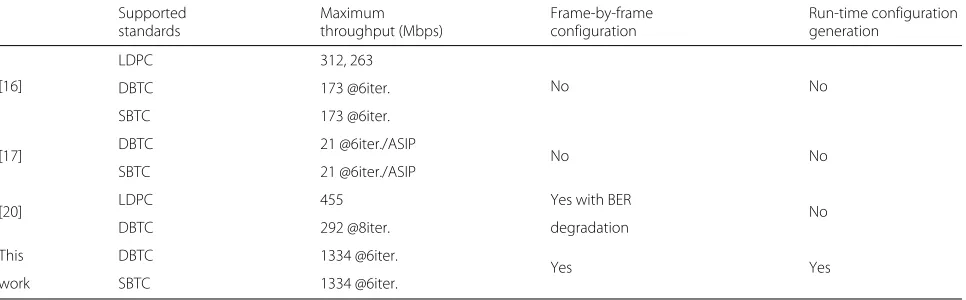
Table 7Comparison of supported dynamic configuration features with relevant existing works
[17] DBTC 21 @6iter./ASIP No No
SBTC 21 @6iter./ASIP
[20] LDPC 455 Yes with BER No
DBTC 292 @8iter. degradation
This DBTC 1334 @6iter.
Yes Yes
work SBTC 1334 @6iter.
The second one concerns throughput values limited by the number of integrated ASIPs in the platform, which are shown in gray cells. In this case, the maximum through-put for a given frame size is determined using results given in Table 4. These results show that the proposed configuration management of the reconfigurable UDec architecture offers an efficient solution respecting the configuration scenario presented in Section 2 with high maximum throughput values up to 667 and 1334 Mbps in serial and shuffled decoding modes, respectively.
Table 7 proposes a comparison of this work with sev-eral relevant works in the literature. The proposed work is the single one that provides a complete solution in order to support a frame-by-frame dynamic configuration management of a multi-processor turbo decoder, which is able to dynamically evaluate and generate the con-figuration data depending on throughput and error rate requirements.
7 Conclusions
This paper presents the first solution that allows a frame-by-frame run-time configuration management of a high-throughput multi-processor turbo decoder. It provides an analysis of the dynamic evolution of the number of decoding iterations regarding the level of sub-block par-allelism in order to be integrated in the configuration management of the UDec architecture. A configuration management, where the configuration information is gen-erated at run-rime has been proposed. This solution provides an efficient method for exploiting the capacity of the reconfigurable UDec architecture while ensuring a frame-by-frame configuration process w.r.t., the appli-cation requirements in terms of throughput and error rate. Considering a maximum configuration latency of 4.586 μs, the maximum throughput supported by the architecture implementing 64 RDecASIPs is 1334 Mbps when shuffled turbo decoding is enabled.
Authors’ contributions
VL designed and implemented the proposed architecture and wrote the paper. AB scientifically supervised the work, provided the simulation results used in this work, and participated in writing the paper. GG and J-PD scientifically supervised the work and contributed in implementing the proposed architecture. All authors read and approved the final manuscript.
Competing interests
The authors declare that they have no competing interests.
Publisher’s Note
Springer Nature remains neutral with regard to jurisdictional claims in published maps and institutional affiliations.
Author details
1Laboratoire Lab-STICC - CNRS, UMR 6285, Centre de Recherche Christiaan Huygens, Rue de Saint-Maudé - BP 92116, 56321 Lorient, France.2Institut Mines-Telecom, Telecom Bretagne, Laboratoire Lab-STICC - CNRS, UMR 6285, Technopôle Brest-Iroise - CS 83818, 29200 Brest, France.
Received: 3 March 2016 Accepted: 22 April 2017
References
1. C Berrou, A Glavieux, P Thitimajshima, inProc. of the IEEE International Conference on Communications (ICC). Near Shannon limit error-correcting coding and decoding: turbo-codes. 1, vol. 2, (1993), pp. 1064–1070. doi:10.1109/ICC.1993.397441
2. 3GPP TS 36.212. Evolved Universal Terrestrial radio access (E-UTRA); multiplexing and channel coding, version 8.4.0 (2008). http://www.etsi. org/deliver/etsi_ts/136200_136299/136212/08.04.00_60/ts_ 136212v080400p.pdf
3. IEEE Standard for Local and Metropolitan Area Networks Part 16: Air Interface for Fixed and Mobile Broadband Wireless Access Systems. (Std., 2006). doi:10.1109/IEEESTD.2006.99107
4. C-C Wong, H-C Chang, Reconfigurable turbo decoder with parallel architecture for 3GPP LTE system. IEEE Trans. Circuits Syst. II: Express Briefs. 57(7), 566–570 (2010). doi:10.1109/TCSII.2010.2048481
5. J-H Kim, I-C Park, inProc. of the IEEE Custom Integrated Circuits Conference (CICC). A unified parallel radix-4 turbo decoder for mobile wimax and 3GPP-LTE, (2009), pp. 487–490. doi:10.1109/CICC.2009.5280790 6. D-S Cho, H-J Park, H-C Park, inProc. of the International Conference on
Telecommunications (ICT). Implementation of an efficient UE decoder for 3G LTE system, (2008), pp. 1–5. doi:10.1109/ICTEL.2008.4652642 7. D Wu, R Asghar, Y Huang, D Liu, inProc. of the IEEE 8th International
8. C-H Lin, C-Y Chen, E-J Chang, A-Y Wu, inProc. of the 13th International Symposium on Integrated Circuits (ISIC). A 0.16nj/bit/iteration 3.38mm2 turbo decoder chip for WiMAX/LTE standards, (2011), pp. 168–171. doi:10.1109/ISICir.2011.6131904
9. M May, T Ilnseher, N Wehn, W Raab, inProc. of the Design, Automation and Test in Europe Conference & Exhibition (DATE). A 150Mbit/s 3GPP LTE turbo code decoder, (2010), pp. 1420–1425. doi:10.1109/DATE.2010.5457035 10. R Shrestha, R Paily, inProc. of the 26th International Conference on VLSI
Design and 12th International Conference on Embedded Systems (VLSID). Design and implementation of a high speed MAP decoder architecture for turbo decoding, (2013), pp. 86–91. doi:10.1109/VLSID.2013.168 11. Xilinx, Partial Reconfiguration User Guide UG702 (v14.5)
12. S Zhang, R Qian, T Peng, R Duan, K Chen, inProc. of the 7th International ICST Conference on Communications and Networking in China (CHINACOM). High throughput turbo decoder design for GPP platform, (2012), pp. 817–821. doi:10.1109/ChinaCom.2012.6417597
13. L Huang, Y Luo, H Wang, F Yang, Z Shi, D Gu, inProc. of the IET International Conference on Communication Technology and Application (ICCTA). A high speed turbo decoder implementation for CPU-based SDR system, (2011), pp. 19–23. doi:10.1049/cp.2011.0622
14. O Muller, A Baghdadi, M Jezequel, inProc. of the Design, Automation and Test in Europe Conference& Exhibition (DATE). ASIP-based multiprocessor SoC design for simple and double binary turbo decoding, vol. 1, (2006), pp. 1–6. doi:10.1109/DATE.2006.244126
15. H Moussa, O Muller, A Baghdadi, M Jezequel, inProc. of the Design, Automation Test in Europe Conference & Exhibition (DATE). Butterfly and Benes-based on-chip communication networks for multiprocessor turbo decoding, (2007), pp. 1–6. doi:10.1109/DATE.2007.364668
16. P Murugappa, A-K R., A Baghdadi, M Jézéquel, inProc. of Design, Automation and Test in Europe Conference & Exhibition (DATE). A flexible high throughput multi-ASIP architecture for LDPC and turbo decoding, (2011), pp. 1–6. doi:10.1109/DATE.2011.5763047
17. C Brehm, T Ilnseher, N Wehn, inProc. of the International SoC Design Conference (ISOCC). A scalable multi-ASIP architecture for standard compliant trellis decoding, (2011), pp. 349–352. doi:10.1109/ISOCC. 2011.6138782
18. T Vogt, N Wehn, A reconfigurable ASIP for convolutional and turbo decoding in an SDR environment. IEEE Trans. Very Large Scale Integration (VLSI) Syst.16(10), 1309–1320 (2008). doi:10.1109/TVLSI.2008.2002428 19. S Kunze, E Matus, G Fettweis, T Kobori, inProc. of the IEEE Workshop on
Signal Processing Systems (SIPS). A “multi-user” approach towards a channel decoder for convolutional, turbo and ldpc codes, (2010), pp. 386–391. http://ieeexplore.ieee.org/document/5624878/ 20. C Condo, M Martina, G Masera, VLSI implementation of a multi-mode
turbo/LDPC decoder architecture. IEEE Trans. Circuits Syst. I: Reg. Papers. 60(6), 1441–1454 (2012). doi:10.1109/TCSI.2012.2221216
21. C Condo, M Martina, G Masera, inProc. of the Design, Automation and Test in Europe Conference & Exhibition (DATE). A network-on-chip-based turbo/LDPC decoder architecture, (2012), pp. 1525–1530. doi:10.1109/DATE.2012.6176715
22. V Lapotre, P Murugappa, G Gogniat, A Baghdadi, M Hubner, J-P Diguet, A dynamically reconfigurable multi-ASIP architecture for multistandard and multimode turbo decoding. IEEE Trans. Very Large Scale Integration (VLSI) Syst.PP(99), 1–1 (2015). doi:10.1109/TVLSI.2015.2396941 23. P Robertson, E Villebrun, P Hoeher, inProc. of the IEEE International
Conference on Communications (ICC). A comparison of optimal and sub-optimal MAP decoding algorithms operating in the log domain, vol. 2, (1995), pp. 1009–10132. doi:10.1109/ICC.1995.524253
24. M Bickerstaff, L Davis, C Thomas, D Garrett, C Nicol, inProc. of the 2003 IEEE International Solid-State Circuits Conference (ISSCC). A 24mb/s radix-4 logmap turbo decoder for 3GPP-HSDPA mobile wireless, (2003), pp. 150–4841. doi:10.1109/ISSCC.2003.1234244
25. G Masera, G Piccinini, MR Roch, M Zamboni, VLSI architectures for turbo codes. IEEE Trans. Very Large Scale Integration (VLSI) Syst.7(3), 369–379 (1999). doi:10.1109/92.784098
26. E Boutillon, WJ Gross, PG Gulak, VLSI architectures for the MAP algorithm. IEEE Trans. Commun.51(2), 175–185 (2003).
doi:10.1109/TCOMM.2003.809247
27. Y Zhang, KK Parhi, inProceedings of the 2004 International Symposium on Circuits and Systems (ISCAS). Parallel turbo decoding, vol. 2, (2004), pp. 509–512. doi:10.1109/ISCAS.2004.1329320
28. O Muller, A Baghdadi, M Jezequel, Parallelism efficiency in convolutional turbo decoding. EURASIP J. Adv. Signal Process.2010(1), 927–920 (2010) 29. J Zhang, MPC Fossorier, Shuffled iterative decoding. IEEE Trans. Commun.
53(2), 209–213 (2005). doi:10.1109/TCOMM.2004.841982
30. O Muller, A Baghdadi, M Jezequel, inInformation and Communication Technologies, 2006. ICTTA ’06. 2nd. Exploring parallel processing levels for convolutional turbo decoding, vol. 2, (2006), pp. 2353–2358.
doi:10.1109/ICTTA.2006.1684774
31. V Lapotre, P Murugappa, G Gogniat, A Baghdadi, M Huebner, J-P Diguet, inProc. of the 2013 16th Euromicro Conference on Digital System Design (DSD). Stopping-free dynamic configuration of a multi-asip turbo decoder, (2013). http://ieeexplore.ieee.org/document/6628272/ 32. V Lapotre, P Murugappa, G Gogniat, A Baghdadi, J-P Diguet, J-N Bazin,
M Huebner, inProc. of the 2013 IEEE International Symposium on Circuits and Systems (ISCAS). Optimizations for an efficient reconfiguration of an ASIP-based turbo decoder, (2013). http://ieeexplore.ieee.org/document/ 6571888/
33. V Lapotre, P Murugappa, G Gogniat, A Baghdadi, M Huebner, J-P Diguet, inProc. of the 2013 IEEE Computer Society Annual Symposium on VLSI (ISVLSI). A reconfigurable multi-standard ASIP-based turbo decoder for an efficient dynamic reconfiguration in a multi-ASIP context, (2013). http:// ieeexplore.ieee.org/document/6654620/
34. C Schurgers, F Catthoor, M Engels, Memory optimization of MAP turbo decoder algorithms. IEEE Trans. Very Large Scale Integration (VLSI) Syst. 9(2), 305–312 (2001). doi:10.1109/92.924051
35. S Benedetto, D Divsalar, G Montorsi, F Pollara, Soft-output decoding algorithms in iterative decoding of turbo codes (1996). The
Telecommunications and Data Acquisition Progress Report 42-124. NASA Code 315-91-20-20-53. https://ipnpr.jpl.nasa.gov/progress_report/42-124/title.htm
Submit your manuscript to a
journal and benefi t from:
7Convenient online submission
7 Rigorous peer review
7Immediate publication on acceptance
7 Open access: articles freely available online
7High visibility within the fi eld
7 Retaining the copyright to your article