Fibre Radio MM-Wave Systems:
Architectural and Interferometric N oise
Considerations
Joseph Carmel Attard
A thesis submitted for the degree o f Doctor o f Philosophy
March 2003
UCL
ProQuest Number: 10013374
All rights reserved
INFORMATION TO ALL USERS
The quality of this reproduction is dependent upon the quality of the copy submitted.
In the unlikely event that the author did not send a complete manuscript and there are missing pages, these will be noted. Also, if material had to be removed,
a note will indicate the deletion.
uest.
ProQuest 10013374
Published by ProQuest LLC(2016). Copyright of the Dissertation is held by the Author.
All rights reserved.
This work is protected against unauthorized copying under Title 17, United States Code. Microform Edition © ProQuest LLC.
ProQuest LLC
789 East Eisenhower Parkway P.O. Box 1346
Acknowledgements
First and foremost I wish to express my sincere gratitude to my supervisors, Professor John J. O ’Reilly and Dr. John E. Mitchell. I would like to thank Professor John J. O ’Reilly for having introduced me to the field and for his constant guidance and encouragement during the course of this research. I would also like to thank Dr. John E. Mitchell for his valuable advice, discussion, and continuous support.
I am grateful to the Association of Commonwealth Universities and Maltacom p.l.c. who have provided the financial support, which enabled me to undertake this programme.
I would like to thank Professor C. Pule, Dr. S. Zammit, and Professor J. Camilleri whose encouragement enabled me to undertake my postgraduate studies.
I would like to acknowledge fruitful discussions with Dr. I. Darwazeh, Prof. I. Henning, Dr. P. M. Lane, Dr. Miguel R. D. Rodrigues and Dr. D. Wake. I would also like to thank and acknowledge research collaborations with Dr. Rob Griffin and Dr. Christian Rasmussen which enabled me to continue my research on their seminal work.
I would like to thank all the present and past members of the Telecommunications Research Group, especially Dr. Jorge Castro and Nishita Hathi, together with all my friends at UCL, who have provided a pleasant working environment and for their continuous encouragement and support.
I would like to thank Dr. T. Crummey for his continuous friendship and encouragement during this programme. I also acknowledge the support given to me by Ing. G. Cauchi. I am also indebted to my family for their constant support and encouragement, particularly my parents and mother in law.
Abstract
The primary goal of this research work is to investigate the development o f full duplex, multi-wavelength, fibre supported mm-wave overlay networks which inherently facilitate the reconfiguration of the wireless network. This network architecture focused approach outlined the need for the subsequent investigation on the impact o f interferometric noise on such networks.
Several network architectures which facilitate the dynamic reconfiguration o f the wireless network have been proposed. This is achieved by the tight integration o f the cellular radio, fibre radio, optical networking and physical layers.
The large scale design o f fibre supported mm-wave overlays necessitates an investigation into the impact of interferometric noise on these overlay networks. A detailed understanding o f the behaviour of an optical distribution network in the presence of unequally powered interferers is carried out and the suitability o f the symbol conditioned Modified Chem off Bound for analysing such networks is established. Mathematical models of different mm-wave generation and modulation imposition techniques, in the presence of self homodyne beat noise, are developed and a comparative assessment of their performance is carried out. This thesis reports the derivation of a set o f equations identifying the interference components generated by crosstalk between different multi-service channels, some o f which are carrying fibre supported mm-wave signals.
Frequency plan limitations for mm-wave WDM overlays, using suppressed optical carrier upconversion are identified following a theoretical and experimental investigation. New configurations for the simultaneous transport (within the same channel) o f a baseband signal and a mm-wave signal, generated by optical suppressed carrier upconversion are proposed and their feasibility is determined.
Contents
Acknowledgem ents...3
Abstract
...4
Contents
...5
List o f Figures...11
List o f T ab les... 14
List o f Abbreviations...15
Chapter 1 Introduction... 18
1.1 Introduction ...18
1.2 Thesis Organisation... 23
1.3 Contributions and Publications... 26
Chapter 2 Overview o f mm-wave fibre radio and optical access
networks... 29
2.1 The MM-wave fibre radio concept... 29
2.2 Survey o f mm-wave generation and modulation imposition techniques... 30
2.2.1 Single Stage Techniques - Three term ... 31
2.2.1.1 External Modulation - Mach Zehnder Modulator (MZM)... 31
2.2.1.2 External Modulation - Electro-absorption Modulator (EAM) ....33
2.2.1.3 Electro-Absorption Transceiver (EAT)... 34
2.2.2 Single Stage techniques - Two-term...34
2.2.2.1 Optical single sideband (OSSB)...35
2.2.2.2 Simultaneous electro-optical up conversion (SEOUC)... 36
2.2.3 Two Term — Dual Stage Techniques, Single Laser Techniques... 36
2.2.3.2 4 f-M eth o d ...37
2.2.3 3 Mode Locking...38
2.2.3.4 Gain Switching...38
2.2.3.5 Two Mode L aser... 38
2.2.4 Two Term — Dual Stage Techniques, Two Laser Techniques...39
2.2.4.1 Optical Frequency Locked Loop (O F L L )... 39
2.2.4.2 Optical Phase Locked Loop (O P L L )...39
2.2.4.3 Optical Feed Forward M odulation...39
2.2.4.4 Optical Injection L ocking...40
2.2.4.5 Spectrum Sliced ASE Technique...40
2.2.5 Dual Stage Two Term Techniques - Modulation Im position...40
2.2.6 Miscellaneous techniques... 42
2.2.6.1 Remote Up conversion... 42
2.2.6 2 Optical Non-Linearity...43
2.2 6.3 Frequency m odulation...43
2.3 Optical Netw ork Im pairm ents... 44
2.3.1 Attenuation, Power budget and Optical Amplifier N o ise...44
2.3.2 Chromatic D ispersion... 44
2.3.2.1 1300nm o p eratio n ... 45
2.3.2.2 Dispersion com pensation...45
2.3.2.3 Dispersion Tolerant T ransp ort... 46
2.3 2.4 Polarisation mode dispersion... 48
2.3.3 Stimulated Brillouin Scattering... 49
2.4 Optical Metropolitan Area and Access N etw orks... 50
2.4.1 Optical hybrid access networks topology and physical co n stru ctio n ...50
2.4.2 Optical access networks technology and standardisation... 52
2.4.2.1 SDH based access netw orks... 52
2.4.2.2 ITU-T Recommendation G.983 series and (FSAN)...52
2.4.2.3 Ethernet Passive Optical N etw orks... 54
2.4.2.4 The SuperPON D em onstrator ... 55
2.4.2.5 Optical CDMA Access N etw orks...56
2.4 2.6 ACTS PRISMA D em onstrator ... 57
Chapter 3
Full D u p lex, M ulti-w avelength FSMS Architectures
supporting D yn am ic R econfiguration o f the W ireless
N etw ork ... 61
3.1 Introduction ... 61
3.2 Classification o f FSMS Architectures... 62
3.2.1 Baseband Downstream—Baseband Upstream architectures... 63
3.2.2 RF Downstream - RF Upstream architectures...64
3.2.3 IF Downstream - IF Upstream architectures... 65
3.2.4 RF Downstream — IF /B B Upstream architectures... 68
3.3 FSMS overlay operation within the ITU -T G.983.3 enhancement band...69
3.3.1 Frequency p la n ... 69
3.3.2 Physical Im plem entation... 70
3.4 Dynamic wireless network reconfiguration... 73
3.4.1 Wavelength —> RAU mapping schem es... 76
3.4.1.1 1 :» Static Wavelength mapping schem e... 76
3.4.1.2 1:1 Static Wavelength mapping scheme... 78
3.4.1.3 1:1 Dynamic Wavelength mapping schem e... 79
3.4.1.4 1:( 1 or n) Dynamic Wavelength mapping schem e...80
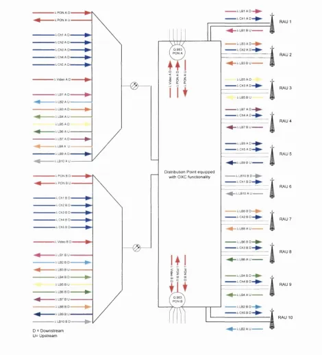
3.4.2 Sub-carrier —^Wavelength—>RAU mapping scheme... 81
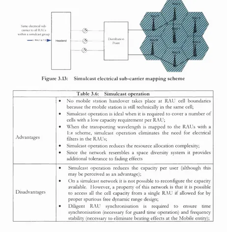
3.4.2.1 Simulcast op eratio n ...82
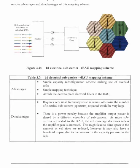
3.4.2 2 1:1 Sub-carrier—>RAU mapping...83
3.4 2.3 Hybrid simulcasting & 1:1 sub-carrier—>RAU mapping scheme .84 3.5 Summary 85
Chapter 4
A nalysis o f the im pact o f unequally pow ered interferers on
the perform ance o f P O N b ased optical netw orks... 86
4.1 Introduction ... 86
4.2 Origin and properties o f interferometric beat noise... 88
4.2.1 Phase noise in semiconductor la sers... 88
4.2.2 Modelling interferometric noise due to multiple interferers... 90
4.2.3 Interferometric noise prop erties... 92
4.3 N etw ork imperfections leading to crosstalk...95
4.4 Interferometric Noise Estimation M eth o d s... 97
4.4.1 The Gaussian approxim ation... 99
4.4.2 Numerical evaluation o f the convolution o f the P D F ...105
4.4.3 Moment Generating Function based techniques... 107
4.4.3.1 The C hem off B o u n d ... 108
4.4.3.2 The Saddlepoint A pproxim ation...108
4,4 3,3 The Modified C hem off Bound (M CB)... 110
4.5 Analysis o f the impact o f unequally powered interferers on network performance 112 4.5.1 Model derivation and assumptions... 113
4.5.2 Results - (Equal Interferers)...117
4.5.3 Benchmarking the Modified C hem off B o u n d ...122
4.5.4 Results (Unequal Interferers)... 127
4.6 Summary 133
Chapter 5 Interferom etric n oise effects in W D M Fibre Supported M M
-wave S ystem s... 134
5.1 Introduction ... 134
5.2 Sources o f interferometric noise in FSMS W DM overlays... 137
5.2.1 Types o f signals present in FSMS W DM overlays... 139
5.2.2 Combinations o f signal — interférer mixing in FSMS W D M overlays 141 5.3 Self homodyne interferometric noise effects in FSMS overlaid system s... 143
5.3.1 Baseband self homodyne beat noise...143
5.3.2 Extemal Modulation at mm-wave self homodyne beat noise...143
5,3.2,1 Impact o f first order approximation for non ideal extinction ,,, 147 5.3.3 DSB-SC (one term) self homodyne beat noise...149
5.3.4 DSB-SC (two term) self homodyne beat noise...152
5.3.5 Comparison o f the self homodyne beat noise effects...153
5.4 Same wavelength Leakage effects in FSMS W DM overlays... 159
5.4.5 DSB-SC (One term) — Baseband signal mixing effects... 161
5.4.6 DSB-SC (Two term) — Baseband signal mixing effects... 162
5.4.7 Mixing effects between signals carrying electrical sub-carriers on different frequencies ...163
5.4.8 Mixing effects between DSB-SC mm-wave signals and externally modulated signals carrying electrical sub-carriers on an IF frequency...163
5.4.9 Summary o f same wavelength Leakage Effects in FSMS W D M overlays 165 5.5 Dissimilar wavelength Leakage effects in FSMS W DM overlays... 167
5.6 Summary 168
Chapter 6 Sensitivity analysis o f a M M -wave / D W D M overlay u sin g
the SE O U C T e c h n iq u e ...170
6.1 Introduction ...170
6.2 M M -wave/DW DM overlay using the SEOUC technique... 172
6.3 Sensitivity to Bias mismatch and drive pow er...173
6.4 Crosstalk power sensitivity to bias mismatch and drive p o w e r... 176
6.4.1 Theoretical model for bias mismatch in a multi-wavelength M Z M ... 183
6.4.2 Experimental determination o f bias mismatch in a SEOUC configuration 185 6.4.3 Crosstalk effects in a SEOUC configuration... 190
6.4.4 Minimum channel spacing in a SEOUC configuration... 196
6.5 Summary 200
Chapter 7 Interleaved B aseband and M M -wave channels in W DM
F S M S ... 203
7.1 Proposed Baseband and RF channel interleaving configurations... 204
7.2 Interleaving Configuration (a)... 206
7.3 Interleaving Configurations (b) and (c)... 216
7.4 Summary 220
Chapter 8 M itigation o f interferometric n o ise in W DM F S M S
221
8.1 Introduction ... 2218.2 Classical interferometric noise mitigation techniques... 222
8.4 Planning and design rules to mitigate interferometric noise in FSMS overlays 225
8.5 Summary 225
Chapter 9
C oncluding rem arks... 226
9.1 Recommendations for future research...229
List of Figures
Figure 1.1: Figure 1.2: Figure 2.1: Figure 2.2: Figure 2.3: Figure 2.4: Figure 2.5: Figure 2.6: Figure 2.7: Figure 2.8: Figure 2.9: Figure 3.1: Figure 3.2: Figure 3.3: Figure 3.4: Figure 3.5: Figure 3.6: Figure 3.7: Figure 3.8: Figure 3.9: Figure 3.10 Figure 3.11 Figure 3.12 Figure 3.13 Figure 3.14 Figure 3.15: Figure 4.1: Figure 4.2: Figure 4.3: Figure 4.4:Layered model o f fibre supported mm-wave radio distribution overlay... 22
Thesis subject area...23
Topology o f a generic FSMS architecture...30
Optical Spectrum o f a three term technique...31
MM-wave generation and modulation imposition techniques... 32
OSSB generation technique...35
Optical suppressed carrier up-conversion...36
Data modulation imposition in a two tone two stage configuration... 41
Remote up-conversion o f baseband m odulation...42
SNR degradation o f mm-wave signal for different lengths o f fib re... 47
Enhancement band defined in ITU-T G.983.3...53
A baseband downstream — baseband upstream architecture... 64
A RF downstream — RF upstream architecture...65
A IF downstream — IF upstream architecture...67
A RF downstream — IF upstream architecture...68
Frequency Plan...69
Modified Frequency P la n ...70
FSMS overlay using Looped Back sources...72
Wireless capacity reconfiguration on an FSMS W DM overlay... 75
1:« Static wavelength mapping schem e...76
1:1 Static wavelength mapping schem e...78
1:1 Dynamic wavelength mapping schem e...79
1:(1 or ft) Dynamic wavelength mapping schem e...80
Simulcast electrical sub-carrier mapping schem e...82
1:1 electrical sub-carrier —>RAU mapping scheme...83
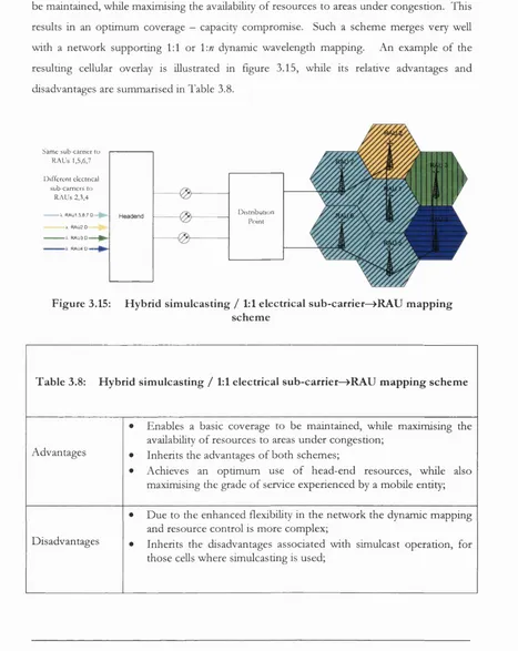
Hybrid simulcasting / 1:1 electrical sub-carrier—>RAU mapping schem e 84 Simulated Laser Phase N oise... 89
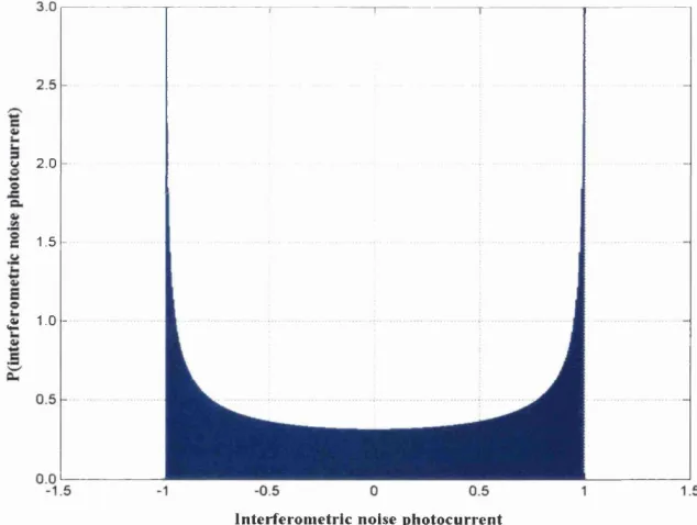
Normalised interferometric noise photocurrent P D F ...94
Histogram o f photocurrent signal samples resulting from beat noise... 95
Figure 4,5: N on symbol conditioned GA and MCB resu lts... 118
Figure 4.6: Symbol conditioned GA and MCB...119
Figure 4,7: Power Penalty for equally powered interferers... 121
Figure 4,8: Plot o f the numerically simulated results... 123
Figure 4.9: Benchmarking simulated and MCB derived results... 125
Figure 4,10: Benchmarking simulated/experimental and MCB derived results... 126
Figure 4,11: Normalised Interférer Power (N = 5 )...128
Figure 4,12: N on symbol conditioned GA and MCB (N = 5 )... 129
Figure 4,13: Symbol conditioned GA and MCB (N = 5 )...130
Figure 4,14: Power penalty for unequally powered interferers... 131
Figure 4,15: Crosstalk power for IdB power penalty...132
Figure 5,1: Sources o f crosstalk on a WDM tree and branch P O N FSMS overlay...138
Figure 5,2: Main source o f inband crosstalk on an optical wavelength distribution ring utilising W DM ... 138
Figure 5,3: Signal Types...139
Figure 5,4: Impact o f using first approx, model with a non ideal extinction... 148
Figure 5,5: BER (for various extinction ratios)...155
Figure 5,6: Power Penalty...156
Figure 5,7: Graphical representation o f the beats generated by the two signal types...158
Figure 5,8: Comparison between the effect o f beat noise and additive crosstalk... 167
Figure 5,9: Comparison o f power penalty incurred by beat noise & additive crosstalk,., 168 Figure 6,1: M M -wave/DW DM overlay using SEOUC up-conversion... 172
Figure 6,2: Sensitivity o f harmonic power to bias voltage m ism atch... 174
Figure 6,3: Sensitivity o f harmonic power to bias voltage mismatch & drive pow er 175 Figure 6,4: Sensitivity o f Crosstalk level to bias voltage m ism atch...177
Figure 6,6: Sensitivity to bias mismatch for various drive pow ers...179
Figure 6,7: (a) Conversion efficiency and (b) Crosstalk isolation, vs, drive pow er... 181
Figure 6,8: Experimental setup...186
Figure 6,9: Experimental results...187
Figure 6,10: Optical carrier suppression vs electrical signal pow er...188
Figure 6,11: Percentage Bias mismatch versus channel frequency... 189
Figure 6.12: Crosstalk in a 75GHz spacing/50GH z mm-wave SEOUC configuration 191 Figure 6.13: Crosstalk in a lOOGHz spacing/50G H z mm-wave SEOUC conflg... 192
Figure 6.15 Figure 6.16 Figure 6.17 Figure 6.18 Figure 6.19 Figure 6.20 Figure 6.21 Figure 7.1; Figure 7.2: Figure 7.3: Figure 7.4: Figure 7.5: Figure 7.6: Figure 7.7: Figure 7.8: Figure 7.9: Figure 7.10: Figure 7.11: Figure 7.12: Figure 7.13: Figure 7.14: Figure 7.15:
Crosstalk in a 150GHz spacing/50GH z mm-wave SEOUC config... 194
Crosstalk in a 200GHz spacing/50GH z mm-wave SEOUC config... 195
BER Penalty in a 75GHz spacing/50GH z mm-wave SEOUC config...197
BER penalty in a lOOGHz spacing/50GH z mm-wave SEOUC config... 197
BER penalty in a 125GHz spacing/50GH z mm-wave SEOUC config... 198
BER penalty in a 150GHz spacing/50GH z mm-wave SEO UC config... 198
BER penalty in a 200GHz spacing/50GH z mm-wave SEOUC config... 199
Simultaneous baseband and RF data signal m odulation... 204
Interleaved baseband and RF data signal with a com mon optical source... 205
Interleaved baseband and RF data signal with different optical sources... 206
Interleaving Configuration (a) in detail... 207
Configuration (a) Simulation Setup in O PTSIM ... 209
Simulated Photocurrent Spectrum with a completely suppressed carrier... 210
Simulated Photocurrent Spectrum with an unsuppressed C arrier... 211
O utput optical spectrum when the upconversion m odulator is driven with a IV signal amplitude, for various bias voltages... 212
Signal power when the upconversion MZM is driven with a signal o f amplitude IV, for various modulation d ep th s...212
O utput optical spectrum when the upconversion m odulator is driven with a 2.5V signal amplitude, for various bias voltages... 213
Signal power when the upconversion MZM is driven with a signal o f amplitude 2,5V, for various modulation depths... 213
O utput optical spectrum when the upconversion m odulator is driven with a 5V signal amplitude, for various bias voltages... 214
Signal power when the upconversion M ZM is driven with a signal o f amplitude 5V, for various modulation depths... 214
Simulated model for configurations (b) and (c)... 217
List of Tables
Table 3.1: Table 3.2: Table 3.3: Table 3.4: Table 3.5: Table 3.6: Table 3.7: Table 3.8: Table 4.1: Table 5.1: Table 5.2: Table 5.3: Table 5.4:
Table 5.5:
Table 5.6: Table 8.1:
Classification o f FSMS A rchitectures...62
\'.n Static wavelength m apping...77
1:1 Static wavelength m apping...78
1:N Dynamic wavelength routing...79
1:(1 or ») Dynamic wavelength mapping scheme...80
Simulcast operation...82
1:1 electrical sub-carrier —>RAU mapping schem e...83
Hybrid simulcasting / 1:1 electrical sub-carrier—>RAU mapping scheme... 84
Principal Interferometric Noise Analysis T echniques... 98
Self homodyne crosstalk combinations...142
Signal-Interferer combinations generated by Leakage effects... 142
Summary o f symbol conditioned normalised photocurrent results... 146
Summary o f symbol conditioned normalised photocurrent results with aligned RF carrier p h ases...146
Summary o f normalised decision variable photocurrents in the presence o f self homodyne beat n o ise...153
Signal-Interferer combinations generated by Leakage effects... 165
List of Abbreviations
ACTS Advanced communication technologies and services
ADM Add D rop Multiplexer
AP Access Point
A P O N ATM P O N
ASE Amplified Spontaneous Emission
ASK Amplitude Shift Keying
AT Access Termination
AWG Arrayed Waveguide Grating
BAF Broadband Access FaciUties
BB Baseband
B E R Bit error rate
BO N A PA R TE Broadband Optical Network using ATM P O N Access facilities in
Realistic Telecommunications Environments.
B -P O N Broadband Passive Optical Network
BPSK Binary Phase Shift Keying
BRAN Broadband Radio Access Network
BSC Base Station Controller
BTS Base Transceiver Station
CATV Cable Television
CDMA Code Division Multiple Access
CL Conversion Loss
CO Central Office
CW Continuous Wave
D BA Dynamic Bandwidth Allocation
D FB laser Distributed Feedback semiconductor laser
DSB-SC D ouble sideband suppressed carrier
DSL Digital Subscriber Line
D V B-T Digital Video Broadcasting - Terrestrial
DW DM D ense Wavelength division multiplexing
EAM Electro Absorption Modulator
EAT Electro Absorption Transceiver
EATX Electro Absorption Transceiver Mixer
E D FA Erbium doped fibre amplifier
E P O N E thernet Passive Optical Network
ERC European Radiocommunications Committee
ETSI European Telecommunications Standards Institute
FM Frequency Modulation
FRANS Fibre Radio ATM Networks and Services AC083
FSAN Full Service Access Network
FSMS Fibre supported mm-wave system
FTTB Fibre to the Building
F T T H Fibre to the Home
FWM Four Wave Mixing
GA Gaussian Approximation
G P O N Gigabit PO N
H FC Hybrid Fibre Coax
H iperaccess High Performance Radio Access System
H ipetL A N Fligh Performance Radio Access Local Area Netw ork
IE E E Institute o f Electrical and Electronics Engineers
IF Intermediate Frequency
IM -D D Intensity Modulation Direct Detection
IT U International Telecommunications Union
LMDS Local Multipoint Distribution System
LO Local Oscillator
MAC Medium Access Control
MBS Mobile Broadband System
MCB Modified C hem off Bound
M E Mobile Entity
MGF M oment Generating Function
m m -wave Millimeter wave
MQW Multiple Quantum Well
MSC Mobile Switching Centre
MVDS Microwave Video Distribution System
MWS Multimedia Wireless System
MZM Mach Zehnder Modulator
OADM Optical Add D rop Multiplexer
OAM Operations Administration and Maintenance
O-CDM A Optical Code Division Multiple Access
O D N Optical Distribution Network
OFLL Optical Frequency Locked Loop
OLT Optical Line Terminal (ITU-T Recommendation G.983)
OMCI O N U Management and control interface
G N U Optical Network Unit (ITU-T Recommendation G.983)
OPLL Optical Phase Locked Loop
OSSB Optical Single Sideband
OXC Optical Cross Connect
PD F Probability density function
P D H Plesiochronous Digital Hierarchy
PL A N E T Photonic local access network
PLL Phase Locked Loop
PLOAM Physical Layer Operations and Maintenance
PM D Polarisation Mode Dispersion
PMP Point to Multipoint
P O N Passive Optical Network
PO P Point o f Presence
PRISMA Photonic routing o f interactive services for mobile applications
QAM Quadrature Amplitude Modulation
RACE Research and technology development in Advanced Communications technologies in Europe
RAU Remote Antenna Unit
RF Radio Frequency
SB s Stimulated Brillouin Scattering
SC-GA Symbol Conditioned Gaussian Approximation
SCM Sub-Carrier Multiplexing
SC-MCB Symbol Conditioned Modified C hem off Bound
SD H Synchronous Digital Hierarchy
SDM A Sub-carrier Division Multiple Access
SDR Software Defined Radio
SEOUC Suppressed Electro Optical Upconversion
S N R Signal to Noise ratio
TOBASCO Towards Broadband Access Systems on CATV Optical Networks
UM TS Universal Mobile Telecommunications System
V DSL Very High Speed Digital Subscriber Line
V LA N Virtual Local Area Network
W DM Wavelength division multiplexing
Chapter 1 — Introduction 18
Chapter 1
Introduction
1.1 Introduction
Research on fibre supported mm-wave radio systems (FSMS) has traditionally concentrated on developing appropriate mm-wave generation techniques, improving device performance and moulding together the system concepts. While, recently lower frequency fibre radio systems designed for providing in building coverage and operating in the 0.8-2.1GHz frequency range have become commercially available, moving the fibre radio system concept outside the laboratory [1].
The key advantages provided by fibre radio namely, low complexity at the remote antenna unit (RAU), transparency, support for high frequency operation and an integrated backhaul are well known. However, despite these strengths, deployment o f fibre radio systems over a wide area or within the access network has not been forthcoming. Currently the low frequency fibre radio systems available on the market are positioned to target the in building coverage segment where the main selling point is their ability to share a com m on in building infrastructure among various operators, and to remotely locate the bulky parts o f the base stations required.
This lack o f m om entum towards the implementation o f fibre radio over the wide area may be attributed to a number o f weaknesses, from which the current formulation o f fibre radio
Chapter 1 — Introduction 19
(ii) The present high cost o f the main device com ponents required to implement an FSMS RAU is a major weakness. Cost is always a tricky aspect to predict because o f its dependency on volume and mass produce-ability. However, a high level analysis in [2] estimates that for the cost o f a RAU to hit the US$100 mark, a 1:1000 reduction in the cost o f the main optical and mm-wave com ponents must occur. It was predicted that this might occur around 2010.
(üi) A fibre connection between the central office and the RAU is required for every RAU. This is a laborious process which is directly proportional to the number o f RAUs.
(iv) Traditionally the radio and optical layers have been treated as two separate layers with no visibility across layers. Although such an arrangement has got its advantages, the combined design o f the radio and optical layers is where a substantial part o f the potential o f FSMS resides
T he FSMS concept is also under threat from a num ber o f factors. It is claimed that one o f the strengths o f a FSMS is the cheaper, more stable, transparent RAU due to the FSMS ability to remote the mm-wave u p/do w n conversion electronics. However, since the same electronics must be present within the mobile stations operating at mm-wave, it is very hard to maintain this hypothesis, even though the required accuracy and stability o f the electronics in the RAU is higher. Simultaneously, transparency may be emulated by Software Defined Radio (SDR) [3] an area which may evolve such that a software reconfigurable base station operating at mm-wave is possible and cheaper than a FSMS RAU. While mobile operators lack an extensive optical fibre access network infrastructure and high costs prohibit them from implementing one.
Chapter 1 — Introduction 20
A lack o f applications requiring broadband on the move may undermine the commercial viability o f a mobile broadband system and consequently ham per its roll out. This subject is currently under close scrutiny within the UMTS vs. Wireless Local Area N etw ork (WLAN) debate. Proponents o f the WLAN model claim that broadband wireless connectivity is only required in certain hotspots such as campuses, airports, cafeterias etc. with universal coverage obtained through UMTS non-broadband macrocell coverage. Partly this debate is fuelled by the difficulty and cost, related to the construction o f a widespread mobile broadband system.
In the meantime the research community has pushed ahead with initiatives to define a fourth generation mobile system [4]. The shift from third generation to fourth generation is expected to support fully converged broadcast and mobile services, diverse user devices, ubiquitous mobile access and software dependency. It is envisaged that the network would offer increased transport rates to users and that it will progressively shift towards higher frequencies as the current radio spectrum gets congested. A wireless broadband periphery mandates the adoption o f a m icro/pico cellular approach and has led to new wireless systems operating at mm-wave frequencies such as Local M ultipoint Distribution System (LMDS) ~ 3OGH2 [5], Microwave video distribution system (MVDS) ~40G H z [6], and Mobile Broadband System (MBS) ~60G H z [7] to be proposed. The large number o f base stations required at these frequencies and the difficulty o f engineering electrical mm-wave systems favours FSMS.
The marriage o f mobility and broadband makes network capacity planning on a short time scale very difficult. Thus a fourth generation system is also seen as one that would enable inter-networking across a hierarchy o f different networks by employing vertical and horizontal handover with underlying highly autonomous adaptive networks capable o f self- managing their structure to meet mobile users’ changing and evolving demands for both services and capacity. These are also expected to be able to achieve dynamically adaptable wireless access including software terminals and reconfigurable base stations, together with the dynamic allocation o f bandwidth to achieve spectrum efficiency [4]. It is here that FSMS may make their mark.
Chapter 1 — Introduction 21
from each in addressing the dynamic adaptability and mobility requirements o f fourth generation systems.
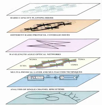
Figure 1.1 illustrates a layered model o f a fibre supported mm-wave radio distribution WDM overlay. It is envisaged that different wireless network operators would lease wavelengths coexisting on the same fibre infrastructure with other services and operators.
The layered model clearly illustrates that such an overlay requires the system to be designed in a vertically integrated way across the optical physical infrastructure layer, the fibre radio full duplex link layer, the optically networked multi-wavelength overlay, together with the wireless network coverage and capacity requirements layers, such that the concept o f a dynamically adaptable network may be realised.
Consequently it may be concluded that prior to the widespread deployment o f FSMS over a wide area the following im portant architectural issues must be
resolved:-(i) The need for a full duplex, network focused, approach to FSMS architecture definition and design;
(ii) The need for fibre radio systems to coexist on the same fibre infrastructure with other fibre radio systems or with other services. This implies a need for the development o f suitable W DM operation and wavelength sharing schemes together with a thorough analysis o f the impact o f optical crosstalk in multi-service, multi-wavelength networks carrying FSMS signals [8].
Figure 1.1: Layered model of fibre supported mm-wave radio distribution overlay
C i
Opa
\
\ \ \
Opm
M
B
S
L
M
D
S
L M D S c e ll plan
\
Transparent Hybrid Fibre Radio
access network
M B S cell p lan
D ifferen t A. plan s fo r in d iv id u al
H y b rid F ib re R ad io In frastru ctu re
R A D I O C A P A C I T Y P L A N N I N G I S S U E S
D I F F E R E N T R A D I O P R O T O C O L C O V E R A G E I S S U E S
W A V E L E N G T H A G I L E O P T I C A L N E T W O R K S
T D M A W D M A
C D M A S C M A
M U L T I X P H Y S I C A L L A Y E R A N D M U L T I A C C E S S T E C H N I Q U E S
A N A L Y S I S O F S I N G L E C H A N N E L H E R S Y T E M S
Chapter 1 — Introduction 23
The main driving force o f this thesis is focused on furthering the body o f knowledge related to fibre supported mm-wave system architectural and interferometric noise considerations, based on the hypothesis that the need for overlaid W DM FSMS to inherently support and facilitate the flexible reconfiguration o f capacity in the radio network would form the main selling point o f FSMS.
It is observed that these issues arise from the merger and overlay, o f three traditionally separate fields o f study, namely fibre supported mm-wave radio distribution, optical access networks and networking, and mm-wave radio systems.
M M -w ave Radio T ech niqu es Fibre
Radio T ech niqu es
O p tical A c c e ss N etw o rk s and N etworking T ech niqu es
Figure 1.2: T hesis subject area
The details o f the thesis organisation and the main thesis contributions are summarised in the following sections.
1.2 T h e sis O rganisation
Chapter 1 — Introduction 24
o f the w ork described together with the setting o f the scene for the subsequent chapter.
A comprehensive review o f the state o f the art in fibre supported mm-wave radio distribution is presented in chapter 2. This includes a survey o f optical millimetre wave generation and modulation imposition techniques for FSMS application together with an overview o f the main optical network impairments affecting the performance o f a FSMS. T he latest developments in optical access distribution and mm-wave radio research are also presented.
In chapter 3 the system configurations, architectural concepts and potential issues when overlaying a FSMS over a multi-wavelength network are examined. This work focuses on the creation o f network architectures that facilitate the dynamic reconfiguration o f the overlaid wireless network. We define a high level classification o f the potential bidirectional FSMS architectures possible, clearly identifying their relative advantages and disadvantages, together with their state o f the art in terms o f pro o f o f concept experiments and field demonstrations.
We also investigate the design o f a FSMS overlay network operating within the enhancement band (proposed in ITU -T G.983.3) o f a G.983 P O N distribution network, where we identify the main issues involved. The main contribution o f this chapter is the comprehensive summary o f the relative merits o f the different Sub-carrier —^Wavelength—>RAU (Remote Antenna Unit) mapping schemes by which the vertical integration o f the various layers illustrated in figure 1.1 may be achieved, and a network architecture supporting the dynamic reconfiguration o f the cellular wireless network designed. This w ork has also served to identify several knowledge gaps that have formed the basis for the subsequent detailed investigation into the impact o f interferometric noise on the performance o f these multi wavelength, multi-service networks
Chapter 1 — Introduction 25
passive optical distribution network is likely to be described by the presence o f unequally powered interferers at the receiver.
Chapter 4 focuses on the analysis and detailed understanding o f the behaviour o f an optical communications system in the presence o f unequally powered interferers at the receiver. An accurate estimate o f the performance o f such networks is required, especially when they are being used for overlaid fibre radio systems, because an overestimate in the interferometric noise power penalty o f a mere 3dB implies that the number o f base stations supported by the optical distribution network is halved.
Analytical work in this chapter is based on the Modified C hem off Bound and it is has been established that this technique is more accurate than the Gaussian approximation when used to analyse the impact o f interferometric noise arising from unequally powered interferers. The performance estimates obtained using the Modified C hem off Bound have also been benchmarked against experimentally verified simulation results and it has been confirmed that the results obtained using this technique are practically indistinguishable from the benchmark results.
Chapter 5 focuses on identifying and analysing elements o f a multi service W DM optical distribution network which merit special attention because some o f the wavelengths o f the system are carrying FSMS services. We identify the main sources o f interferometric noise in multi-wavelength networks carrying FSMS together with the various types o f signals that may be present on such a network. This enables us to classify and investigate the interferometric noise arising from the various types o f signal—interférer mixing combinations. The symbol conditioned Modified C hem off Bound technique is used throughout to enable a performance estimate to be obtained. We also compare the performance o f the various signal types in the presence o f self homodyne beat noise to highlight any differences between baseband signal behaviour and fibre radio signal behaviour.
Chapter 1 — Introduction 26
as a set o f planning rules for the design o f mm-wave /D W D M overlays utilising the suppressed optical carrier up-conversion technique.
In chapter 7 we investigate the feasibility o f increasing the optical spectral efficiency o f the m m -w ave/D W D M overlay by interleaving a baseband data signal in the centre o f a channel occupied by a two tone mm-wave signal generated by an optical suppressed carrier upconversion technique. Several configurations which enable this to be achieved have been designed and their feasibility investigated, using simulated models.
In chapter 8 we investigate the applicability o f classical interferometric noise mitigation techniques to multi-wavelength FSMS overlays. We also bring together the results obtained in this thesis to form a set o f planning and design rules which enable the reduction or mitigation o f interferometric noise in such networks.
Chapter 9 concludes this thesis, summarising the main contributions and suggesting some future research directions.
1.3 C ontributions and P u blications
The primary goal o f this research work was to investigate the development o f fuU duplex multi-wavelength FSMS overlay networks which inherently facilitate the reconfiguration o f the wireless network. This network architecture focused approach outlined the need for the subsequent investigation on the impact o f interferometric noise on these multi-wavelength, multi-service, overlay networks. The main contributions o f this research work are summarised
below:-• A novel, vertically integrated, network focused approach is developed. This approach resulted in the proposal o f several new architectures which facilitate the dynamic reconfiguration o f the wireless network, achieved by tight integration o f the cellular radio, fibre radio, optical networking and physical layers.
Chapter 1 — Introduction 27
more efficient utilisation o f bandwidth.
• A detailed analysis o f the performance o f optical systems, in the presence o f unequally powered interferers is carried out, using the symbol conditioned and non-conditioned forms o f both the Modified C hem off Bound and the Gaussian approximation techniques. The analysis explains, for the first time, the reasons behind the opposing performance trends predicted in the literature when using the symbol conditioned forms o f these techniques.
• We verify the accuracy o f the results obtained when using the symbol conditioned Modified C hem off Bound to study the im pact o f interferometric noise on the performance o f optical networks. This is done by comparing our MCB results to experimentally verified simulation results obtained from collaborative work carried out with the Technical University o f Denmark [169].
• D evelopm ent o f mathematical models o f different mm-wave generation and modulation imposition techniques, in the presence o f self homodyne beat noise. Such models are used to compare the performance o f the different techniques under self homodyne beat noise conditions.
• Derivation o f a set o f equations identifying the interference com ponents generated by crosstalk between different multi-service channels (fibre radio/fibre radio and fibre radio/other services). This was the result o f a thorough study o f the various crosstalk signal combinations present in a multi-service multi-wavelength network, where some o f the wavelengths are carrying fibre radio mm-wave signals.
• Identification o f frequency plan limitations for mm-wave W DM overlay, using suppressed optical carrier upconversion, resulting from theoretical and experimental investigations.
• We propose new configurations for the simultaneous transport (within the same channel) o f a baseband signal and a mm-wave signal, generated by optical suppressed carrier upconversion, and determine their feasibüity.
Chapter 1 — Introduction 28
This research reported in this thesis has led to the following publications
1. O ’Reilly J J , Lane P.M., Attard J.C. and Griffin R., “Broadband wireless Systems & Networks: an enabling role for radio over fibre”, Phil. Trans. R. Soc. Lond. A (2000), 358, 2283-2296.
2. Attard J.C., Mitchell J.E., Lane P.M., and O ’Reilly J.J, “System considerations related to the overlay o f fibre supported mm-wave radio systems on optical access networks”, Proc. 6* European Conference on Networks and Optical Communications (N O C ’2001), edited by Lord. A., Faulkner D.W., and Smith D.W., lO S Press, Amsterdam, 2001.
3. Attard J.C. and Mitchell J.E., “A comparison o f the performance o f different fibre radio mm-wave modulation imposition techniques in the presence o f self homodyne beat noise”. Wireless Design conference, W DC 2002, London, May 2002.
4. Attard J.C., Mitchell J.E., and O ’Reilly J.J, “Crosstalk considerations in mm-wave radio over fibre systems with interleaved baseband channels” XVIII World Telecommunications Congress 2002 (WTC’2002), Paris, 2002.
5. Attard J.C. and Mitchell J.E., “Fibre radio mm-wave radio system configurations utilizing a W DM overlay on a P O N ”, Optical Hybrid Access Networks 2002 (O H A N ’2002), Florence, 2002.
6. Attard J.C. and Mitchell J.E., “An analysis o f the impact o f unequally powered interferers on the performance o f optical communication networks”. International Conference on Telecommunications, ICT 2002, China, June 2002.
7. Attard J.C. and Mitchell J.E., “Fibre supported mm-wave systems”. Tutorial, International Conference on Telecommunications, ICT 2002, China, June 2002.
Chapter 2 — Overview o f mm-wave fibre radio and optical access networks 29
Chapter 2
O verview o f m m -wave fibre radio
and optical access netw orks
2.1 T h e M M -w ave fibre radio co n cep t
The topology o f a generic fibre supported mm-wave radio system (FSMS) is shown in Figure 2.1. O n the downlink, from the base unit at the central office towards the remote antenna unit (RAU), the data/optical interface needs to generate an optical signal and impose the modulation required, such that the resulting optical signal can be detected and processed, to yield the required mm-wave radio frequency (RF) signal. The optical network distributes this optical signal to a number o f RAUs where the optical to RF conversion occurs. The RAU radiates the RF signal and the mobile entity (ME) receives the signal.
The RAU also serves to receive the RF signal radiated from the M E and to convert it into an optical signal suitable for the upward transmission towards the base unit inside the central office, where it is received and the data extracted. The main strengths o f the FSMS concept are summarised
below:-(i) Reduced complexity at the RAU. This can be achieved because modulation/dem odulation, up/dow n-conversion and multiplexing can be performed at the central office base unit which serves several RAUs. This reduces the relative RAU size and increases the flexibility.
Chapter 2 — Overview o f mm-wave fibre radio and optical access networks 30 3
I
ZI
Base unit Data/ optical interface Central OfficeO ptical m m -w ave generation and
m odulation im p osition
Optical network
i-'i
i
Optical Network
/
RAU RAU RAU O ptical netw ork and link im pairm entsR em ote A n ten na U m t
Mobile Entity
Radio
i\ir
Interface
Figure 2.1: Topology of a generic FSMS architecture
(iii) M oving to a m ic ro /p ic o cellular arrangem ent using the cu rren t practice o f
interconnecting base stations to the m obile sw itching centre (MSC) using point-to-
p o in t circuits w ould require a huge am ount o f such circuits. A FSMS im proves the
situation since it also provides an integrated backhaul m echanism .
(iv) T ransparency - C hanges in the m odulation form at may be acco m m o d ated because the
FSMS is transparent to the m odulation form at and the wireless protocol.
T ransparency is also a function o f the simplicity o f the R A U , since the less functions
are perfo rm ed in the RAU the m ore transparent it is.
(v) E ase o f o peration at m m -w ave frequencies due to the optical transport.
2.2 Survey of m m -wave generation and m odulation
im position techniques
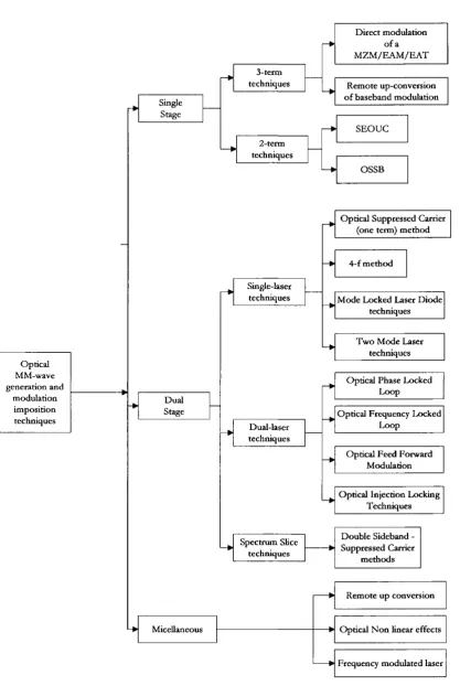
O v e r recent years there has been a proliferation o f techniques developed for the generation
o f optical m illim etre wave signals and for the im position o f the m odulation. Broadly, these
techniques can be divided into tw o
classes:-(i) Single stage techniques, w here the generation o f the m m -w ave and the m odulation
im position are perfo rm ed in the sam e stage and;
Chapter 2 — Overview o f mm-wave fibre radio and optical access networks 31
imposition are performed in two, separate, cascaded stages.
The relationship between these broad classes and their subclasses is illustrated in Figure 2.3.
2.2.1 Single Stage T echniques - Three term
Three term techniques are intrinsically single stage techniques. They are based on the conventional intensity modulation o f an optical signal using an optical intensity modulator such as a Mach Zehnder Modulator (MZM) or an Electro-Absorption Modulator (RAM) that can operate at mm-wave frequencies. The optical spectrum generated consists o f an optical carrier centred between two modulation sidebands as shown in Figure 2.2.
However, as the optical signal propagates along an optical fibre, chromatic dispersion causes a relative phase change between the three components leading to a cyclic variation o f the generated electrical pow er with fibre distance or frequency. A t mm-wave frequencies this effect limits the usefulness o f 3-term techniques (without dispersion compensation) to fibre reaches o f only a few km.
Figure 2.2: Optical Spectrum o f a three term technique
2.2.1.1 E xternal M odulation - M ach Zehnder M odulator (M ZM )
Chapter 2 — Overview o f mm-wave fibre radio and optical access networks 32 Single Stage Dual Stage Single-laser techniques 2-term techniques Dual-laser techniques
4 - f m ethod 3-term
techniques
S E O U C
Spectrum Slice techniques
OSSB
Micellaneous
Optical Phase Locked L oop
Optical Feed Forward M odulation Optical Frequency Locked
L oop
M ode Locked Laser D iode techniques
T w o M ode Laser techniques
Optical Injection Locking Techniques
Optical N o n linear effects
Frequency modulated laser Rem ote up conversion R em ote up-conversion o f baseband modulation
Optical Suppressed Carrier (one term) m ethod
D ou ble Sideband -Suppressed Carrier
m ethods D irect modulation
o f a M Z M /E A M /E A T
Optical MM-wave generation and
modulation im position techniques
Chapter 2 — Overview o f mm-wave fibre radio and optical access networks 33
y
With a D C bias o f , a linear intensity — voltage response is achieved for small amplitude
modulation signals. The intrinsic bandwidth o f the electro optic effect in LiN bO j is very high however, the practical difficulty when constructing mm-wave modulators is to achieve velocity matching between the propagating optical and electrical waves over the electrode interaction length [9]. Modulation frequencies up to 75G Hz have been demonstrated [10,11], but the problem o f velocity matching results in an increasing optical insertion loss, drive power requirement and unit cost along with the device bandwidth.
Operating the laser in continuous mode has the advantage o f reducing the relative intensity noise (RJN) significantly. Although the MZM co-sinusoidal transfer function leads to inter modulation products, linearization techniques such as electrical pre-distortion [12] and optical linearization techniques, such as the optical dual parallel [13,14], the optical dual cascade [15] and the optical feed-forward technique [16] have been developed. Accurate and stable M ZM biasing is also required in order to reduce the am ount o f inter modulation distortion.
2.2.1.2 External M odulation - Electro-absorption M odulator (EAM )
More recently, electro-absorption modulators (EAM) based on III-V semiconductor technology have been developed. These devices offer the possibility o f electro-absorption operation utilising the Franz-Keldysh effect in bulk material or the Q uantum confined Stark effect in multiple quantum well structures.
Chapter 2 — Overview o f mm-wave fibre radio and optical access networks 34
transmitted light through the EAM together with the required intensity modulation [24].
2.2.1.3 Electro-A bsorption Transceiver (EAT)
A feature o f electro-absorption waveguide structures is that they can be utilised both for modulation and photodetection, thus enabling the assembly o f an electro-absorption transceiver (EAT) as a single device. An EA T chip consists o f three regions a photodetection, a passive waveguide and a modulation section constructed by having two absorption regions consisting o f tensile strained InG aA sP /InG aA sP multiple quantum wells on both sides o f a passive waveguide region [25]. EAM, 60GHz, technology has made steady progress from a 1-port EA T to a 2-port EA T [26]. Advantages o f the EA T include compactness, low drive power and adaptability to W DM technologies.
Bi-directional transmission using an EAT, o f a 156M bit/s 60GHz band signal over 25Km has been dem onstrated in [26]. Although more research is required to manufacture a cost effective E A T operating at mm-wave frequencies, while optimising the modulation characteristics and responsivity o f the device and minimising crosstalk between the two channels, this device is very promising.
The EA T can operate in a completely passive mode making it possible to construct simple RAUs with a low device count, however the limited dynamic range and output power from the passive E A T make a passive EA T better suited for picocellular environments [27].
Recently a p ro o f o f concept experiment using an electro-absorption transceiver mixer (EATX) device has been demonstrated [25]. The EA TX simultaneously acts as a mm-wave photodetector, an IF band external modulator, and an IF-to-RF upconverter. However, m ore work needs to be carried out before its practical realisation.
2.2.2 Single Stage techniques - Two-term
Chapter 2 - Overview o f mm-wave fibre radio and optical access networks 35
know n as optical heterodyne techniques. In o rd e r to generate a n arrow linew idth RF signal,
the phase noise o f the tw o optical co m p o n en ts m ust be correlated. M uch o f the w ork in the
literature concerns the various m eth o d s that have been p ro p o se d for obtaining correlated
phase noise in the tw o optical term s such as obtaining the tw o tones from a single optical
source, cancelling the phase noise, o r im plem enting phase tracking feedback loops [28].
2.2.2.1 Optical single sideband (OSSB)
A single stage, tw o-term technique is the optical single sideband (OSSB) technique p ro posed
in [29]. A n OSSB signal can be generated using a single, dual electrode M Z M in the
configuration show n in Figure 2.4. T h e m odulated m m -w ave signal is applied to one arm o f
the dual electrode M ZM , while a replica o f the sam e signal is delayed by 7l/2 and applied to
the o th e r arm. T h e resulting optical spectrum is also show n in Figure 2.4. A lthough this
m eth o d requires the dual electrode M ZM to be driven at the m m -w ave frequency, the
conversion efficiency d em onstrated is good. T h e m ain advantage o f the O SSB technique is
that the m m -w ave generation and the m odulation im position are carried o u t in a single stage
requiring a single, dual arm M ZM . A n OSSB signal may also be generated by optically
filtering (removing) one o f the sidebands o f a three-term technique, how ever this is not very
pow er efficient [30]. O th e r techniques include a com bination o f an external m odulator and
phase m odulator in cascade [31], and a m onohthically integrated D F B laser w ith a m ultim ode
interferom eter [32].
Dual Drive Mach Zehnder Modulator
MZM biased at quadrature
Delay 0=7t/2
Rl- Drive
Chapter 2 — Overview o f mm-wave fibre radio and optical access networks 36
2.2.2.2 Sim ultaneous electro-optical up conversion (SE O U C )
The Simultaneous electro optical up conversion (SEOUC) m ethod is covered in detail in section 6.2, In this approach, baseband radio sub-carriers are applied directly to DW DM optical sources. The modulated optical signals are then multiplexed and the composite signal is upconverted to mm-wave frequency using a M ZM to perform optical suppressed carrier upconversion [33,34]. This m ethod is very attractive for FSMS W DM overlays because o f the ease with which W DM concepts may be applied.
2.2.3 T w o Term — D ual Stage T ech n iqu es, Single Laser
T echniques
2.2.3.1 O ptical su pp ressed carrier up-conversion
This technique is also known as the 2f-method. Proposed in [35] optical suppressed carrier upconversion is very similar to double sideband suppressed carrier signal (DSB-SC) generation. It makes use o f a single laser source incident on a M ZM biased at the point o f minimum transmission (V„). The technique and the resulting optical spectrum are illustrated in Figure 2.5.
Mach Zehnder Modulator
à I
MZM biased at minimum transmission
RF D rive
f f f -f f f + f f
o m m o o m m
Chapter 2 — Overview o f mm-wave fibre radio and optical access networks 37
The resulting electrical field spectrum at the output o f an ideal chirp free Mach Zehnder Modulator (MZM), when driven with a pure carrier is shown in Equation (2.1).
^out
-y, ( ^ ) cos ± (0 j
-cos
2 y +
A (^ ) cos ± + <^pn ( 0
(2.1)
where, the normalised drive f3 = {nA / 2V^ ) , the optical power, the voltage required to switch the m odulator from on to off, û)^, the optical carrier frequency and the RF frequency respectively, A. the amplitude o f the mm-wave drive signal, (f ) the phase noise of the optical carrier and J^ the Bessel function o f the first kind o f order n.
The m ost significant harmonics are separated by twice the frequency o f the drive signal. Since these harmonics are derived from the same optical source their phase noise is correlated and as long as this correlation is maintained, the electrical signal generated by the heterodyning o f these two components will have a narrow linewidth.
An advantage o f this m ethod is that the MZM is driven at a frequency, which is half that o f the required mm-wave frequency. Although allowing the use o f a lower bandwidth device, the conversion o f M ZM drive power to mm-wave power is poor, unless the MZM is driven very hard. The technique has been demonstrated in [36,37].
2.2.3.2 4f- M eth od
Chapter 2 — Overview o f mm-wave fibre radio and optical access networks 38
2.2.3.3 M ode L ocking
An approach to develop ultra fast broadband lasers is to modify the frequency response o f a lower bandwidth device so as to enhance the modulation response at a particular desired frequency. M ode locking is a special case o f this resonant modulation. The laser is driven with a frequency matched to the optical round trip time o f the laser cavity, which may be an external or extended cavity. In this case however a wavelength selective element is included in the laser cavity to Limit the num ber o f longitudinal laser modes. Resonant modulation fixes the relative phase between adjacent modes, producing an output train o f short pulses at a repetition frequency equal to the modulation frequency. D epending on the number o f modes, the output pulses may be much shorter than the repetition rate, and hence they produce substantial power at harmonics o f the modulation frequency when incident on a photodetector [39,40,41].
2.2.3.4 Gain Sw itching
Gain switching is an alternative means o f producing short pulses with high harmonic content. This approach relies on the non-linear interaction between carrier and photon populations w hen the laser is driven with a large modulation signal at high frequency [42]. Gain switching produces a pulse train similar to that achieved by m ode locking, but the time bandwidth product for the gain switched pulses may be substantially higher than for mode locked pulses.
2.2 3.5 T w o M od e Laser
Chapter 2 — Overview o f mm-wave fibre radio and optical access networks 39
achieve injection locking, but at the expense o f more complex optical spectra.
2.2.4 T w o Term — D ual Stage T echniques, T w o Laser
T ech n iq u es
2.2.4.1 O ptical Frequency L ocked L oop (OFLL)
DFB semiconductor lasers are single mode and widely tuneable, and it is reasonably straightforward to control the optical frequency difference between two lasers [44,45]. A problem with this approach is however laser phase noise. Since the two optical components separated by the mm-wave frequency originate in different lasers, the linewidth o f the mm- wave generated electrical signal is equal to the sum o f the individual laser Hnewidths because the phases o f the two lasers are not correlated. Therefore lasers with a very narrow linewidth must be used. However, techniques to reduce laser phase noise generally reduce either the robustness or the tenability compared to a monolithic laser. Short delay electronics must also be used.
2.2.4.2 O ptical P hase L ocked L oop (OPLL)
In the optical phase locked loop (OPLL) technique, a portion o f the detected beat signal is mixed with a local oscillator, filtered, and fed back to a slave laser to track phase fluctuations of the master laser [46,47]. Since the phase fluctuations o f the master laser are tracked by the slave laser, the detected beat signal exhibits good spectral purity. The fundamental problem with this im plementation is that the loop gain-bandwidth, and hence the phase noise reduction is limited by the practically achievable loop delay.
2.2.4.3 O ptical F eed Forward M odulation
Chapter 2 — Overview o f mm-wave fibre radio and optical access networks 40
2.2.4.4 O ptical Injection L ocking
In this technique multiple side-bands are first induced in a seed laser, either by direct or external modulation. This signal is then fed to two frequency controlled lasers whose free running optical frequencies are matched to sidebands separated by the desired frequency. W ith sufficient seed power, the phase noise o f the two slave lasers then becomes correlated. D ue to the correlation o f the slave lasers locked to the side bands o f the master laser, a beat signal with very narrow line width is produced [49,50].
2.2.4.5 Sp ectm m Sliced ASE T ech n iq u e
In this technique the amplified spontaneous emission (ASE) generated by an erbium doped fibre amplifier (EDFA) is sliced by an arrayed waveguide-grating filter to generate a spectrum slice. The spectrum slice is then used as the optical source in an optical suppressed carrier up-conversion set up. After being generated the two optical terms need to be amplified. Since the two components originate from the same spectrum slice their noise is correlated resulting in a very narrow electrical linewidth after heterodyning. In [51] this technique has been demonstrated over a fibre span o f 25Km. Over longer fibre, the different propagation velocities o f the two slices leads to a de-correlation o f the noise, resulting in the appearance o f a noise pedestal in the generated electrical signal. This m ethod is however attractive because it may be used as a cheap source for W DM based systems where the slices are generated by slicing a wideband noise source with an arrayed waveguide router.
2.2.5 Dual Stage T w o Term T echniques - M odulation
Im position
Chapter 2 — Overview o f mm-wave fibre radio and optical access networks 41
Mach Zehnder Modulator
Filter
IF Data Bias Vpi
(a)
Mach Zehnder Modulator
(b)
<
IF data Bias Vpi/2
Figure 2.6: D ata m odulation im position in a two tone two stage configuration (a) D ouble side-band suppressed carrier (O ne Term)
(b) D ouble side band suppressed carrier (Two term)
Imposing data on a two-tone optical signal by intensity modulation o f only one field com ponent retains the dispersion insensitive property o f the simple carrier signal [19]. When such a technique is used with an optical suppressed carrier setup we refer to it as a double side-band suppressed carrier (one term) technique. In this technique linearity is limited by the sinusoidal transfer function o f the MZM used for intensity modulation. Furtherm ore most potential two-tone optical sources produce two frequency com ponents within a single waveguide. Separation o f the components requires an accurate, stable optical frequency demultiplexer with good isolation since leakage between the channels can result in a significant system power penalty.
Chapter 2 — Overview o f mm-wave fibre radio and optical access networks 42
2.2.6 M iscellaneous techniques
2.2.6.1 R em ote U p-conversion
T he underlying principle o f remote up-conversion is the transmission o f a low frequency reference signal to the antenna unit instead o f the mm-wave signal. Using this low frequency reference signal the mm-wave signal is generated at the radio base stations. A more complex antenna unit is therefore required as discussed in more detail in section 3.2.3.
Baseband
I data
Dual Drive Mach 2^hnder
Modulator
Optical
Bandpass
Filter
MZM biased at
quadrature j RF Drive
Figure 2.7: Rem ote up-conversion o f baseband m odulation [53]
Figure 2.7 illustrates a setup based on this principle. D em onstrated in [53] this m ethod uses a single, dual electrode MZM, biased at quadrature, to simultaneously transmit the baseband channel and the local oscillator signal. An RF signal at half the required local oscillator frequency is applied to one arm o f the MZM while the baseband channel is applied to the other arm. A t the modulator output, an optical filter suppresses any second order sidebands generated. After filtration the optical spectrum consists o f a modulated optical carrier and two tones on either side o f the carrier spaced at half the local oscillator frequency from the carrier.