Air flow around suspended cables
Irena Gobiowska1, Maciej Dutkiewicz1,* 1
Faculty of Civil, Environmental Engineering and Architecture, Department of Building Construction, University of Science and Technology in Bydgoszcz, ul. Prof. S. Kaliskiego 7, 85-796 Bydgoszcz, Poland.
Abstract. The impact of wind on construction structures is essential issue in design and operation. In particular, the wind can cause the dengerous vibrations of slender structures with low rigidity, eg. vibrations of cables of suspension and cable-stayed bridges or high voltage transmision lines, thus understanding of wind flow around such constructions is significant. In the paper the results of the analysis of wind flow around the cables for different Reynolds number is presented. The analysed flow meets the Navier-Stokes and continuity equations. The circle and elipse section of the cable is analysed. The discusion of vorticity, drag and lift coefficients and cases due to different angle of wind flow action is presented. The boundary layer and its infuence on total flow is analysed.
1
Introduction
High-rise buildings, chimneys, suspended and stayed bridge, voltage transsmision lines are the examples of slender structures. As vibration due to wind flow can significantly reduce the time of operating of the objects, hence this impact must be taken into account at the design stage and later during operation.
From the point of aerodynamics, the bodies are divided on: streamlined - elongated in the direction of the fluid flow such as cross sections used for wings of aircrafts, and bluff bodies. Above listed objects belong to the bluff bodies group. The fluid flow around these objects is characterized by numerous physical complex phenomena. This flow is determined, when three parameters are known: pressure, velocity, and density that describe the fluid. In the general case, these parameters are functions of time and space. When the parameters depend on time, the flow is unsteady (non-stationary), if depend on space, the flow is un-uniform. The nature of the fluid flow is characterized by Reynolds number which presents the relations between inertial and viscous forces.
Fluid flow analysis around the smooth cylinder were the subject of many authors' studies [8-13].In the literature flow regimes are devided in several states [1-7]. According to [3] for lower values of the Reynolds number such as Re<< 1, the flow is steady and balanced. For Re א (5; 40) - the flow is steady, laminar, some vortices form themselves symmetrically in wake. For Re
א (40; 100 000) flow is in subcritical range, flow is unsteady, turbulent, vortical and unsymmetrical. The Karman street is formed, the frequency of vortices is described by Strouhal number. For Re א (105; 3,5*106) flow is in critical and supercritical range, unsteady, turbulent. For Re > 3,5 * 106 the flow is supercritical. Location of points of separation of the boundary layer on the walls of the body is critical from the point of aerodynamical influence on the body.
The phenomena of interaction between solid bodies and the flow of air is significant from the point of induced vibrations.
In this paper the air flow past the cable of circle and ellipse section for Reynolds numbers in the range of Re א (10; 105) is analysed. The ellipse section can present the variation in cross shape due to e.g. icing of the construction of the cable located in the open space.
2 Wind flow around the cable's
cross-section
Analysed model with the mesh of flow domain and general assumption of inflow direction and section of cable is shown in Fig.1. The analysis is performed for different fixed Reynolds numbers for circle and ellipse sections. The assumption that air is incompressible is made.
Fig.1. Analysed model
The basic equation of motion follows from the momentum conservation principle. This principle implies that the derivative of the velocity of air inside the volume V with respect to time is equal to the sum of the external forces acting on the area. According to d'Alembert, formulation of this principle can be written as follows [1]:
ම ߩ݀࢜݀ݐ ܸ݀ ൌ ම ߩࡲ ܸ݀ ඵ ݀ܣሺͳሻ where
ߩ ௗ࢜ௗ௧ܸ݀ - means inertia forces,
ߩࡲ ܸ݀ - means the sum of the mass forces acting on the volume 'V',
݀ܣ - means the sum of the pressure acting on the entire surface 'A',
The folowing equation was obtained using the Gauss-Ostrogradski theorem for equation and pA = - n p (1):
ම ߩ݀࢜ ݀ݐ ܸ݀ െ ම ߩࡲ ܸ݀ ම ݃ݎܽ݀ ܸ݀ ൌ Ͳሺʹሻ
The sum of integrands functions must be equal to zero for any volume 'V'
:
݀࢜
݀ݐ ൌ ࡲെ ͳ
ߩ݃ݎܽ݀ሺ͵ሻ
Using Newton's hypothesis concerning the relationship between stress and deformation of air, the Navier-Stokes equation is obtained in the form:
݀࢜
݀ݐൌ ࡲെͳߩ݃ݎܽ݀ ߤଶݒሺͶሻ
where ߩ is air density, ݒ - velocity of flow, t time, p is air pressure and ߤ is the coefficient of viscosity.
The purpose of the analysis of the above equation is to determine the relationship between pressure and velocity of flow, in particular the analysis of phenomena occurring at the air / cable contact. The above equation for each direction has the following form:
߲ݒ௫ ߲ݐ ݒ௫ ߲ݒ௫ ߲ݔ ݒ௬ ߲ݒ௫ ߲ݕ ݒ௭ ߲ݒ௫ ߲ݖ ൌ ܺ െͳߩ߲߲ݔ ߤ ቆ߲߲ݔଶݒଶ௫߲߲ݕଶݒଶ௫߲߲ݖଶݒଶ௫ቇ ሺͷܽሻ ߲ݒ௬ ߲ݐ ݒ௫ ߲ݒ௬ ߲ݔ ݒ௬ ߲ݒ௬ ߲ݕ ݒ௭ ߲ݒ௬ ߲ݖ ൌ ܻ െͳߩ߲߲ݕ ߤ ቆ߲߲ݔଶݒଶ௬߲߲ݕଶݒଶ௬߲߲ݖଶݒଶ௬ቇ ሺͷܾሻ ߲ݒ௭ ߲ݐ ݒ௫ ߲ݒ௭ ߲ݔ ݒ௬ ߲ݒ௭ ߲ݕ ݒ௭ ߲ݒ௭ ߲ݖ ൌ ܼ െߩͳ߲߲ݖ ߤ ቆ߲߲ݔଶݒଶ௭߲߲ݕଶݒଶ௭߲߲ݖଶݒଶ௭ቇ ሺͷܿሻ
For the constant density the continuity equation has the following form: ߲ݒ௫ ߲ݔ ߲ݒ௬ ߲ݕ ߲ݒ௭ ߲ݖ ൌ Ͳሺሻ
Among parameters that describe the fluid flow is vorticity.
Vorticity is a measure of the rotation of the air element as it moves in the flow field, and is defined as the curl of the velocity vector:
ࣈ ൌ ݔ࢜ሺሻ
where: is the operator, ࢜ is flow velocity.
In a two-dimensional flow where the velocity is independent of the 'z' coordinate and has no z component, the following equation has the form:
ࣈ ൌ ቆμμ୷െμμ୶ቇ ࢠሺͺሻ
This parameter is analysed in the next clause of the paper in the context of circle and ellipse section of the cylinder for the fix Reynolds number.
3. Results and discusion
The wind around the cable, that is modeled as smooth cylinder, of infinite length of circle and ellipse section was analysed. Diameter of the circle is 120mm, for ellipse: major diameter is 180mm and minor diameter is 120 mm. The 'x' and 'y' direction of the wind is analysed and 'z' component is zero, so two dimensional character of the phenomen is considered. The model presented in the paper was created with use of Ansys Fluent. The unsteady flow for stream simualtion around cylinders with fixed Reynolds numbers was used. For improving accuracy of results, 22650 elements were applied. Navier Stokes equations were solved numerically with use of Semi Implicit Method for Pressure Linked Equations with sequenced calculations of velocity and pressure's components. The coefficients of subrelaxations were additionally used for stabilizing the calculations process. Additionaly, second order upwind method for momentum equations was adopted. At the inlet the velocity is equal to 1m/s and at the outlet the gauge pressure is equal to zero.
much more bigger then inertia forces. At high Reynolds number the inertia forces will dominate the viscous forces. Depending on Reynolds numbers of the flow, different flow regimes will occur.
For fixed Reynolds number Re=0,01 and both circle section as well as ellipse one, the distribution of pressure and velocity, is symmetrical and boundary layer do not separate from cylinder wall at any point. Flow field is steady (Fig. 2 and 3).
Fig. 2. Pressure, velocity contours for circle section of cable for Re=0,01
Fig.3. Pressure, velocity for elipse section and Re=0,01.
For Re = 200 wake becomes unsteady and vortices appear (Fig. 4 i 5, Re=200).
Fig.5. Pressure, velocity for elipse section and Re=200
Further increase of Reynolds number results in a decrease of the distance between the vortices, vortices tear-off time is shorter and wake increases for the circle and ellipse sections (Fig. 6 and 7).
Fig.6. Pressure, velocity contours for circle section of cable for Re=25000
Fig.7. Pressure, velocity for elipse section and Re=25000
Figure 8 shows the results of calculations of drag and lift coefficients for various values of the Reynolds number and circle and ellipse cross-sections.
Fig.8. Drag coefficient Cd and lift coefficient Cl against Reynolds number, for ellipse and circle cross-sections.
3 2 1 0 1 2 3 4 5
10 100 1000 10000 100000
Cd/Cl
Re
Cd_circl Cd_ellip
Fig. 9.Drag coefficient Cd and lift coefficient Cl against angle of wind action, for ellipse cross-section and Re=30000
For ellipse the Cd coefficient has much higher value than for the circle in the analysed range of Reynolds number. Coefficient Cl takes positive and negative values for ellipse section.
Figure 9 shows the drag and lift coefficients for different angle of air inflow for ellipse section and Re = 30000.
Due to contact of the air with the cylinder, the boundary layer is formed. At a small distance from the surface, a strong velocity gradient is formed. For Re = 25 000 the maximal width of the boundary layer is 8mm for and ellipse section and 5mm for circle section.
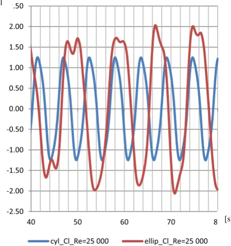
Dependence of drag, lift coefficients and flow time are shown on figures 10 and 11. Both for circle and elipse sections drag and lift coefficients show the periodic oscillations with higher frequency for circle than ellipse section. Some disturbances come from vortex shedding process from both side of the cylinder.
Fig.10 Flow time of drag coefficient Cd, for circle and ellipse section, Re=25 000
Fig.11 Flow time of lift coefficient Cl, for circle and ellipse sections, Re=25 000
Figure 12 present the magnitude of the vorticity vector for circle and ellipse section and Re = 25 000.
Fluid around the ellipse section show the higher vorticity magnitude compared to circle section.
Fig.12 Dependence of vorticity magnitude for circle and ellipse sections, Re=25 000 on angle describing the analysed point on cylinder
3 2 1 0 1 2 3 4 5
10 10 30 50 70 90
Cd/Cl
angle
Cd_ellip_Re30000 Cl_ellip_Re30000
0.00 0.50 1.00 1.50 2.00 2.50 3.00 3.50 4.00 4.50 5.00
40 50 60 70 80
cyl_Cd_Re=25000 ellip_Cd_Re=25000
2.50 2.00 1.50 1.00 0.50 0.00 0.50 1.00 1.50 2.00 2.50
40 50 60 70 80
cyl_Cl_Re=25000 ellip_Cl_Re=25000
0 50 100 150 200 250 300 350 400 450
Vorticity,
[1/s]
angle,degree
Vor_circl_Re25000 Vor_ellip_Re25000
[s]
[s] Cl
5. Summary and Conclusions
In the paper the flow past cable with circle and ellipse cross-section was discussed. Drag and lift coefficients for different Reynolds numbers and angle of wind action were analyzed. These coefficients were analyzed in the time domain. For ellipse, the Cd coefficient has much higher values than for the circle one, in the analysed range of Reynolds number.
Both in the case of circle and ellipse cross-section, oscillation frequency of drag coefficient is higher than oscillation frequency of lift coefficient Besides that, oscillation frequency of drag and lift coefficients for circle section is higher than oscillation frequency of drag and lift coefficients for ellipse section.
Also the vorticity magnitude was analysed. Fluid around the ellipse section show the higher vorticity compared to circle section.
References
1. Zdravkovich, M. M. (1997). Flow around cylindrical structures. Vol 1: Fundamentals. Oxford University Press.
2. Williamson, C. H. K. (1996). Vortex dynamics in the cylinder wake. Annu.Rev. Fluid Mech., 28:477–539. 3. A. Flaga, InĪynieria Wiatrowa, Arkady, Warszawa 2008
4. J.A.uraski, ObciąĪenia wiatrem budowli i konstrukcji, Arkady Warszawa 1978
5. Z.Orzechowski, J.Prywer, R.Zarzycki, Mechanika páynów w inĪynierii Ğrodowiska, WNT, Warszawa 1997 6.J.Bukowski Mechanika Páynów, PWN Warszawa 1975 7. H.Rouse Elementary Mechanics of Fluids, John Wiley and Sons, New York 1948
8. B. Hunt Fluid Mechanics for Civil Engineers, Christchurch, New Zealand, 1995
9. B.R.Munson, Fundamentals of fluid mechanics, 6th ed., New York, John Wiley, 2009
10. S.C.R. Dennis, G.Z. Chang, Numerical solutions for steady flow past a circular cylinder at Reynolds numbers up to 100, J. Fluid Mech. 42 (1970) 471.
11. S.Y. Tuann, M.D. Olson, Numerical studies of the flow around a circular cylinder by a finite element method, Comput. Fluids 6 (1978) 219.
12. M.M. Alam, M. Moriya, K. Takai, H. Sakamoto, Fluctuating Àuid forces acting on two circular cylinders in a tandem arrangement at a subcritical Reynolds number, Journal of Wind Engineering Industrial Aerodynamics, 91, 139–154, 2003