IJEDR1603070
International Journal of Engineering Development and Research (www.ijedr.org)427
Checking sustainability through Finite Element
Analysis of a designed steam piping system using
CAESAR II
1Mohammad Taseem Rafique Kadagaonkar, 2Milind S. Yadav Department of Mechanical Engineering
Finolex Academy of Management and Technology Ratnagiri-415612, Maharashtra, India
________________________________________________________________________________________________________
Abstract - In manufacturing facilities of the petro-chemical, pharmaceutical, chemical, food, beverages and other processing industries use of piping is significant. Process piping is a form of pipe work used to transport materials used in industrial processes and manufacturing. It is specially designed for particular applications to ensure that it will meet health and safety standards, in addition to suiting the needs of a given manufacturing process. In this particular study, by using data like P & ID, a 2-D and isometric drawings of a steam piping system were prepared and designed by following codes and standards. Finite element analysis is performed in this study with the application of various loading cases to check sustainability of piping system in design service condition in stress analysis software called CAESAR II. The results of the study show that primary and secondary stresses were within the code allowable limits hence this system is safe. Nodal movements at corresponding nodes are also shown in displacement report.
Keywords - Process piping, stress analysis, CAESAR II, piping design
I. INTRODUCTION
Process piping is the system of pipes that transport process fluid like air, steam, water, industrial gases, and fuels, chemicals around an industrial facility involved in manufacture of product or in generation of Power. The term piping means not only pipe but includes components like fittings, flanges, valves, bolts, gaskets, bellows etc. [2] Materials selection for achievement of metallurgical stability shall be made on the basis of design condition and to resist possible exposures against fire, corrosion, operating condition, service etc. The designer is confronted with the following concerns regarding the material of construction as he begins the design. These are:
a) Resistance to stress b) Resistance to wear c) Design Life
d) Resistance to corrosion etc.
The code followed for this piping is ASME B 31.3. The design, fabrication, installation, erection, commissioning and inspection are carried out as per code ASME B 31.3.
A. Applications:
• This type of piping can be used in a wide variety of ways. In food manufacturing, for example, process piping can be used to transport food ingredients to various points on the assembly line.
• Chemical manufacturing facilities use this type of piping to transport components of their products along with materials like natural gases used in manufacturing. [1]
• Refineries and similar facilities also utilize it to move chemical compounds. • In power plants, to connect various equipments.
B. Codes and standards:
For scientific design of Piping Systems, selection of proper material of construction and to detail out the material specification, knowledge of Codes and Standards is essential. Standardization can, and does, reduce cost, inconvenience, and confusion that result from unnecessary and undesirable difference is systems, components and procedures. Professional societies, committees and trade organization publish industry standards. A code is basically a standard that has been generally accepted by the government. The objective of each code is to ensure public and industrial safety in a particular activity or equipment. Codes or often developed good engineering practices and published as Recommended Practices. The intent of these documents is misunderstood since, definition of codes, standards and recommended practices are not always correctly understood. [2]
1) Codes: Piping codes defines the requirements of design, fabrication, use of materials, tests and inspection of pipes and
piping systems.
2) Standards: A standards can be defined as set of technical definitions and guidelines-“how to” instruction for designers
IJEDR1603070
International Journal of Engineering Development and Research (www.ijedr.org)428
3) ASME B 31.3 Codes for Pressure Piping: Provide requirements for design, erection, materials, inspection, fabrication,
testing for process piping in petroleum refineries, chemical plants, pharmaceutical plants, textile plants, paper plants, Semiconductor Plants, Cryogenic.
C. Problem definition:
The aim of proposed paper is checking sustainability of the piping system in service condition through finite element analysis which has been already designed. The designed piping isometric drawing which is shown ahead in this paper is taken as input in CAESAR II software.
II.STRESS ANALYSIS OF CASE STUDY
Stress Analysis is a subject, which is more talked about and less understood. The Objective of pipe stress analysis is to ensure safety against failure of the Piping System by verifying the structural integrity against the loading conditions, both internal and external stresses expected to occur during the lifetime of the system in the plant. [2] A piping system will undergo dimensional changes with any change in temperature. If it is constrained from free expansion or contraction, it will be displaced from it unrestrained position causing strain and stresses. [3]
A. Objective:
• The scope of this document is to calculate the static stresses, displacements, forces and moments acting (internally & externally) on the piping system interaction under various conditions/cases (e.g. sustained, expansion and operating) due to the combined effect of internal pressure, system temperature, bending and external loads etc.
• For each system, detailed stress calculations using Caesar II version 5.10.03 have been carried out and a report has been prepared.
B. Methodology:
• Pipeline routing is done by using line list, P& ID, Plot plan etc.
• isometrics have been prepared using Isogen on the basis of the piping routing layouts.
• To ensure realistic conservative boundary conditions, the models have been terminated at supports having guides plus stops.
• For the loads, system weight, internal pressure and temperature expansion have been considered. [4] C. Assumptions and considerations:
• All valve and flange weight are considered from Caesar library.
• The analysis is carried out as below:
1. The system is analyzed for design and operating temperature and pressure conditions. 2. The Design input parameters are considered as per Line List.
3. The standard guide gap is 3 mm.
4. The friction coefficient at restraints is 0.3 for Steel to Steel. D. Codes and standards:
The following codes and standards form the basis of the Stress Analysis:
• ASME B 31.3 for Process Piping
• ASME B16.5 for Pipe Flanged and flanged fittings
• ASME B 36.10 for Welded and Seamless Wrought Steel Pipe. E. Load cases:
The following load cases have been considered for the analysis: 1. (OPE) W+T1+P1
2. (SUS) W+P1 3. (EXP) L4=L2-L3 Where,
WW = Weight of pipe with water. W = Weight of pipe and contents P1 = Design Pressure
T1 = Design temperature F. Given case:
Pipe material: ASTM A106 B Seamless pipe Pipe OD=14 inches at start
Internal Pressure= 4.5 bar for steam as working fluid Temperature= 392 F.
Corrosion allowance is taken as 0.125” [5]
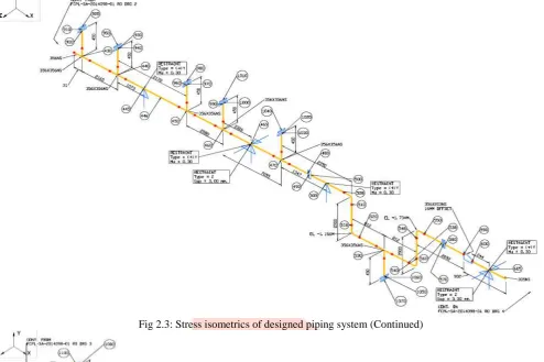
The given piping system is shown in isometrics form below in the stress isometrics. G. Results:
IJEDR1603070
International Journal of Engineering Development and Research (www.ijedr.org)429
H. Isometric:The isometric model of the piping system which was taken as input for stress analysis is shown below. [6]
Fig 2.1: Stress isometrics of designed piping system.
IJEDR1603070
International Journal of Engineering Development and Research (www.ijedr.org)430
Fig 2.3: Stress isometrics of designed piping system (Continued)Fig 2.4: Stress isometrics of designed piping system (Continued)
IJEDR1603070
International Journal of Engineering Development and Research (www.ijedr.org)431
data into the Input Spreadsheet of the Piping module of CAESAR II, each element is taken at a time with corresponding node numbers and details like size and length in X,Y,Z direction of that element, type of material, wall thickness, corrosion allowance, type of restraint, insulation thickness, temperature and pressure is entered.I. Input listing:
The size, type and length of each element between the two nodes are given in detail in the results of the analysis report. The element maybe a part of pipe, a flange, a valve, reducer or any other fitting or instrument. Few input listings can be discussed as below.
A pipe element of material A 106 B having diameter of 355.6 mm diameter is there between nodes 10 and 20. It is 130.175 mm long with wall thickness 11.125 mm and having insulation of 50 mm. Its rigid weight is 538.23 N. Between nodes 20 to 30 there is pipe element having length 239.65 mm.
A flange with rigid weight 538.23 N and dimension 130.175 mm in the direction of run of pipe is present between node numbers 30 and 40. After that there is a valve between node numbers 40 and 50 having length 414 mm. Then a flange with rigid weight 538.23 N and dimension 130.175 mm in the direction of run of pipe on next side if valve between nodes 50 and 60.
A long reducing elbow element is present between the nodes 61 to 65. It is a 90̊ angle elbow. The element between node numbers 400 to 410 is a welding TEE. It is 1725 mm long. Reducers are also used here to connect pipe of different sizes. Between node numbers 630 and 640 reducer is used to connect 12 inch and 10 inch pipes. It has 203mm length.
J. Stress summary:
Highest Stresses Mini Statement Various Load Cases
LOAD CASE DEFINITION KEY CASE 2 (SUS) W+P1
CASE 3 (EXP) L3=L1-L2
Piping Code: B31.3 = B31.3 -2006, May 31, 2007
CODE STRESS CHECK PASSED: LOADCASE 2 (SUS) W+P1
Highest Stresses: ( KPa ) Code Stress Ratio (%): 29.5 @Node 420 Code Stress: 40620.4 Allowable: 137895.1 Axial Stress: 5307.7 @Node 510
Bending Stress: 36010.9 @Node 420 Torsion Stress: 1948.2 @Node 389 Hoop Stress: 9514.8 @Node 600
CODE STRESS CHECK PASSED : LOADCASE 3 (EXP) L3=L1-L2
Highest Stresses: ( KPa ) CodeStress Ratio (%): 45.9 @Node 160
Code Stress: 153527.2 Allowable: 334474.7 Axial Stress: 3806.4 @Node 75
Bending Stress: 153526.5 @Node 160 Torsion Stress: 15674.2 @Node 389 Hoop Stress: 0.0 @Node 20 [4]
IJEDR1603070
International Journal of Engineering Development and Research (www.ijedr.org)432
Fig 3.1: Nodal displacements in X-direction (OPE) Fig 3.2: Nodal displacements in Y-direction in (OPE)Fig 3.3: Nodal displacements in Z-direction (OPE)
Fig 3.4: Nodal displacements in Y-direction (SUS) Fig 3.5: Nodal displacements in Z-direction in (SUS)
There will be change in the piping system in terms of displacements during the service life of the system. This is mainly because of the thermal expansion of the system at high temperature, weight of the own system etc. There are displacements at the nodes of the analyzed piping system. Some of the nodes are selected to show displacements at corresponding nodes. These displacements with their node numbers are shown in graphical form above. Figure 3.1, 3.2, 3.3 shows the shows the nodal movement of the piping system in X-direction, in Y-direction and in Z-direction respectively during operating case where temperature is considered. Here in operating case which is shown in red graph, we can see that maximum displacement is in X-direction as seen in the figure 3.1. That means the nodal movement of the pipe is more along with the run of the pipe. While in the sustained case the nodal movements are zero at the corresponding nodes in X direction. So nodal movements in Y and Z directions are shown in blue lined-graph in figure 3.4 and figure 3.5 respectively. Here, nodal movements in Y-direction are higher. The own weight of the system is along Y-direction (Vertical direction).
III. CONCLUSION: The routed line was stress analyzed to check its sustainability.
0 10 20 30 40 50 60 70 80 90
650 700 750 800
Series1 Dis p lace m en t in m m Node Numbers -0.6 -0.5 -0.4 -0.3 -0.2 -0.1 0 0.1 0.2 0.3
680 700 720 740 760 780
Series1 Node Numbers Dis p lace m en t in m m -0.2 -0.15 -0.1 -0.05 0 0.05 0.1
680 700 720 740 760 780
Series1 Dis p lace m en t in m m Node Numbers -0.6 -0.5 -0.4 -0.3 -0.2 -0.1 0 0.1 0.2 0.3
680 700 720 740 760 780
Series1 Dis p lace m en t in m m
Node Numbers -0.002
-0.001 0 0.001 0.002 0.003 0.004 0.005
680 700 720 740 760 780
IJEDR1603070
International Journal of Engineering Development and Research (www.ijedr.org)433
Pipe supports were provided to the pipes for carrying their weight (pipe weight+ insulation weight+ fluid weight) to avoid vibrations, shock movements for flexibility of the line. Supporting elements were directed towards preventing piping stresses in excess of those permitted in the code, leakage at joints, excessive thrust and movements on connected equipment, excessive stresses in the supporting elements etc. Anchors, Line stops, Guides, Rests were used as for support of the line.From the results of the stress analysis we can also conclude that, the primary and secondary stresses were within the code allowable limits.
Also the loads on restraints / supports were within the practical limits. There were no abnormal values of loads observed in terms of corresponding pipe sizes.
It’s important to intensify the technical and administrative measures and understanding material strength relationship between treated substances and the equipment. [7]
REFERENCES
[1] Chi-Hui Chien, Chun-Hung Chen, Applying statistical methodology to monitor the piping conditions iin petroleum process, Journal of loss prevention©Department of Mechanical and Electro-Mechanical Engineering, National Sun Yat-Sen University, Kaohsiung 80424, Taiwan
[2] A course material in process piping as per ASME B 31.3
[3] Young Hwan Choi, Su Yeong Choi,Assessment of socket weld integrity in piping, Journal Loss prevention in the process industries (Print): pp. 850-853, 2009 © KoreaAtomic Energy Research Institute,150 Dukjin, Yusung Daejeon, 305-353, republic of Korea
[4]B B Karezsi, A G Kotousov, J W H Price, Experimental apparatus for thermal shock fatigue investigations, Journal on pressure vessels and piping©Department of Mechanical Engineering, Monash University, Australia
[5] A problem as case study given by ‘Seven lines, Pune’ [6] Results obtained in Caesar II version 5.10.03