Efficient Analysis of Multilayered Dielectric Rods by Equivalent
Microwave Network Method
Liangqi Gui1, Cong Zhou1, *, Xinxin Tian2, Fan Yang3, and Yao-Jiang Zhang4
Abstract—Multilayered dielectric rods are widely used, and the analysis of their electromagnetic scattering properties is very important in practical design. Based on our former work on the single layer dielectric rod forest, the equivalent microwave network method (EMN) is applied to analyse the concentric and eccentric multilayered dielectric rods in this article. The key step is to obtain the reflection matrix of the multilayered dielectric. Based on the EMN method, the electromagnetic scattering properties of a novel electromagnetic band gap (EBG) structure are calculated. The EBG structure is formed by periodically embedding multilayered dielectric rods into the original dielectric between power/ground planes. The accuracy and efficiency of the EMN method are verified by comparing with the simulation results by the FIT simulator CST. In addition, the EMN method takes about 1 minute to obtain the results, while the simulator takes nearly 20 hours with the same computer.
1. INTRODUCTION
As a typical 2-D electromagnetic (EM) computing problem, scattering by cylindrical structures is widely studied. A great variety of practical scatterers can be modeled as single layer cylindrical rods or multilayered cylindrical rods. One of the most important scattering parameters is the radar cross section (RCS). For a cylinder of infinite length l, the 3-D RCS for normal incidence is related to 2-D scattering width (SW) [1].
Previous investigations that estimate the scattering properties of cylindrical structures exist in the literature. The scattering characteristics of single or multiple cylindrical rods in a nonabsorbent or absorbing medium have been studied in [2–5]. The scattering of oblique incident electromagnetic wave into cylindrical rods array is calculated in [6]. Multilayered eccentric dielectric rods are studied by the indirect mode-matching solution in [7–9]. Rigorous Coupled Wave Analysis (RCWA) algorithm is applied in [10–12] to study EM scattering by multi-eccentric circular or elliptical cylinders. For single layer dielectric rod forest, we have analysed the EM properties in [13, 14], and the equivalent microwave network method (EMN) is applied in the analysis process.
For multilayered rods, the scattering analysis algorithms mentioned above are complex and time-consuming. Based on our former work on single layer rod [13, 14], the EMN method is proposed in this paper to analyze the multilayered rod. Generalized scattering matrix, namely, S-parameters matrix is used to characterize the scattering properties of each interface between different materials. Electromagnetic fields are expressed in terms of cylindrical waves. Then the S-parameters matrix of a multilayered dielectric rod is calculated by microwave network method, and the reflection matrix of multilayered rod is deduced from S-parameters matrix. By loading the reflection matrix to the
Received 8 November 2016, Accepted 30 December 2016, Scheduled 15 January 2017 * Corresponding author: Cong Zhou ([email protected]).
radial scattering matrix of parallel plate pair, the performance of a novel EBG structure can be easily calculated.
The proposed method converts complex scattering problems into microwave network issues. It keeps the accuracy of field matching method and simplifies the analysis procedure. Furthermore, it possesses a clear physical conception and provides convenience for analysing multiple rods and multilayered cylindrical rods.
This paper is organized as follows. In Section 2, the geometries and EM models of concentric and eccentric multilayered rods are presented. In Section 3, the scattering parameters of multilayered rods array are derived. In Section 4, several examples are provided to demonstrate the accuracy of EMN by comparing with the full-wave solver CST.
2. RADIAL SCATTERING MATRIX FOR MULTILAYERED DIELECTRIC RODS 2.1. Scattering Matrix of Two Adjacent Layers
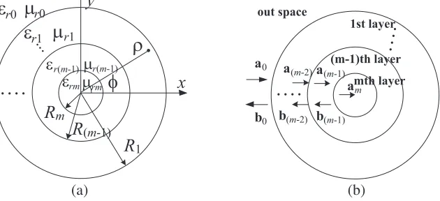
The geometric drawing of a m-layer dielectric rod is shown in Fig. 1. The relative permittivity and relative permeability of each layer areεr0, εr1, . . . , εrm andμr0, μr1, . . . , μrm. The subscript 0 means the
outer space and the subscriptm means the innermost layer. The cylindrical coordinate is set up at the center of the rod. A plane wave travels in the +x direction. According to [15], the incident fields and scattered fields can be expressed by Bessel and Hankel function, respectively. For theith and (i+ 1)th layer, the electric and magnetic field can be written as
Ei = az Ni
n=−Ni
ainJn(kiρ) +binH(n2)(kiρ)
ejnϕ (1)
Ei+1 = az
Ni+1
n=−Ni+1
ani+1Jn(ki+1ρ) +bni+1H(n2)(ki+1ρ)
ejnϕ (2)
Hϕi = aϕ ki
μ0μri Ni
n=−Ni
ainJn(kiρ) +binH(n2)(kiρ)
ejnϕ (3)
Hϕi+1 = aϕ ki+1
μ0μr(i+1)
Ni+1
n=−Ni+1
ain+1Jn(ki+1ρ) +bin+1H (2)
n (ki+1ρ)
ejnϕ (4)
whereki=k0√εriμri,ki+1=k0√εr(i+1)μr(i+1). μ0 is the permeability of free space andk0 is the wave
number in free space. ain and bin represent the unknown amplitude coefficients of incident fields and
out space
1st layer (m-1)th layer
mth layer a0
b0
a(m-2)a(m-1) am
b(m-2) b(m-1) . . . .
. . . .
. . . .
y
x
R
mR
1R
(m-1)r0 r1 r0
r1
rm rm
ε
ε
μ
...μ
r(m-1) ε μr(m-1)
ε μ
ρ
φ
(a) (b)
scattered fields respectively in the ith layer. The truncation number Ni and Ni+1 could be different
for each layer and they are set as a fixed integer N in this article. To facilitate further discussions, the expansion coefficients ain,bin,ai+1
n and bin+1 are arranged into vectors in the following sequences as
shown in Fig. 1.
ai = ai−N ai−N+1 . . . aiNT (5)
bi = bi−N bi−N+1 . . . biNT (6)
ai+1 =
ai+1
−N ai−+1N+1 . . . ai +1 N
T
(7)
bi+1 =
bi+1
−N bi−+1N+1 . . . bi +1 N
T
(8)
Assuming that the interface between the ith and (i+ 1)th layer is a two-port microwave device, the four expansion coefficient vectors can be related by a generalized scattering matrix Si:
bi ai+1
= [Si]
ai bi+1
(9)
The generalized scattering matrix can be expressed as following submatrices:
[Si] =
S11 i S12 i S21 i S22 i
(10)
The four submatrices S∗∗i in Si are (2N + 1)∗(2N + 1) diagonal matrices. According to the boundary condition of dielectric rod in cylindrical coordinate:
Ei = Ei+1 (11)
Hϕi = Hϕi+1 (12)
Eqs. (1)–(4) can be written as
ainJn(kiRi+1) +binHn(2)(kiRi+1) = ani+1Jn(ki+1Ri+1) +bni+1Hn(2)(ki+1Ri+1) (13) k1
μr1
[ainJn(kiRi+1) +binHn(2)(kiRi+1)] = μk2 r2
[ain+1Jn(ki+1Ri+1) +bin+1Hn(2)(ki+1Ri+1)] (14)
Substituting Eqs. (13) and (14) into Eqs. (9) and (10) leads to
S11 i= diag kiμr(i+1)J
n(kiRi+1)∗Jn(ki+1Ri+1)−Jn(kiRi+1)∗ki+1μriJn(ki+1Ri+1) H(2)
n (kiRi+1)∗ki+1μriJn(ki+1Ri+1)−kiμr(i+1)H (2)
n (kiRi+1)∗Jn(ki+1Ri+1)
(15)
S12 i= diag H
(2)
n (ki+1Ri+1)∗ki+1μriJn(ki+1Ri+1)−ki+1μriH (2)
n (ki+1Ri+1∗Jn(ki+1Ri+1) H(2)
n (kiRi+1)∗ki+1μriJn(ki+1Ri+1)−kiμr(i+1)H (2)
n (kiRi+1)∗Jn(ki+1Ri+1)
(16)
S21 i= diag kiμr(i+1)J
n(kiRi+1)∗H (2)
n (kiRi+1)−Jn(kiRi+1)∗kiμr(i+1)H (2)
n (kiRi+1) H(2)
n (kiRi+1)∗ki+1μriJn(ki+1Ri+1)−kiμr(i+1)H (2)
n (kiRi+1)∗Jn(ki+1Ri+1)
(17)
S22 i= diag H
(2)
n (ki+1Ri+1)∗kiμr(i+1)H (2)
n (kiRi+1)−ki+1μriHn(2)(ki+1Ri+1∗Hn(2)(kiRi+1) H(2)
n (kiRi+1)∗ki+1μriJn(ki+1Ri+1)−kiμr(i+1)H (2)
n (kiRi+1)∗Jn(ki+1Ri+1)
(18)
2.2. Reflection Coefficient of a Single-Layer Rod
For the innermost layer of the multilayered rod, two types are considered as shown in Fig. 2: the PEC rod and the dielectric rod.
For a PEC rod, there are no electric or magnetic fields inside the conductor. The boundary condition is
PEC dielectric
(a) (b)
Figure 2. Innermost layer: (a) PEC, (b) dielectric.
From Eq. (1), Eq. (19) can be expressed as
am−1
n Jn(km−1Rm) +bnm−1Hn(2)(km−1Rm) = 0 (20)
The reflection coefficient Γmn−1 is
Γmn−1 = b
m−1 n am−1
n =−
Jn(km−1Rm) H(2)
n (km−1Rm)
(21)
For a dielectric rod, there are no scattered fields inside the dielectric, which means bm = 0 in Eq. (9). Thus, the reflection coefficient Γmn−1 for a dielectric rod can be expressed as
Γmn−1 = bm−
1 n am−1
n =S
n
11m−1 (22)
Sn
11m−1 is the nth element of the diagonal matrixS11 m−1.
Thus, reflection matrixΓm−1, which is a (2N + 1)∗(2N + 1) diagonal matrix consisting of Γmn−1, can be defined to expressed the relationship between am−1 and bm−1:
bm−1 =Γm−1am−1 (23)
2.3. Reflection Matrix of Multilayered Concentric Dielectric Rod
The reflection matrixΓ0of the m-layer concentric dielectric rod can be obtained by iterative calculation. The reflection matrixΓm−1of themth layer is shown in Section 2.2. In the (m−1)thlayer, the scattering
equation is
bm−2 am−1
=
S11 m−2 S12 m−2 S21 m−2 S22 m−2
am−2 bm−1
(24)
Substituting Eq. (23) into Eq. (24) leads to
bm−2 =
S11 m−2+S12 m−2Γ−1m−1−S22 m−2−1S21 m−2
am−2 (25)
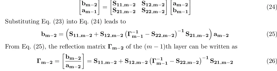
From Eq. (25), the reflection matrixΓm−2 of the (m−1)th layer can be written as Γm−2=
bm−2 am−2
=S11 m−2+S12 m−2Γm−1−1 −S22 m−2−1S21 m−2 (26) Repeating the calculation process of Eqs. (24) and (25), the reflection matrixΓ0, as shown in Fig. 3, can be obtained by iterative calculation.
2.4. Reflection Matrix of Multilayered Eccentric Dielectric Rod
In Section 2.3, the cylindrical coordinate is set up at the center of the rod. For the eccentric dielectric rod, the center of each layer varies. The main issue to get the reflection matrix is to adjust the coefficients to fit the varying local coordinate.
S
Γ
0 m-2
0
S
Γ
m-2S
m-1Γ
m-1 . . ..Figure 3. Reflection matrix of each layer.
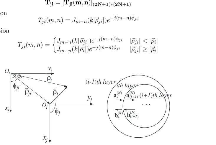
expressed by the Bessel function and the Hankel function. When the local coordinate changes from
xioiyi to xjojyj, as shown in Fig. 4, the Bessel function and the Hankel function should be re-expressed
by a transformation matrix Tji. According to the Bessel addition theorem, the transformation matrix can be written as
Tji= [Tji(m,n)](2N+1)∗(2N+1) (27)
for the Bessel function
Tji(m, n) =Jm−n(k|ρji|)e−j(m−n)φji (28) for the Hankel function
Tji(m, n) =
Jm−n(k|ρji|)e−j(m−n)φji |ρji|<|ρi|
Jm−n(k|ρi|)e−j(m−n)φji |ρji| ≥ |ρi| (29)
O
x
y i
ji
(i-1)th layer
ith layer
a(N)
. . .
i a
(N)
(i+1)
i
i Oj
y
jx
jφ
jφ
ji
ρ
iφ
ρ
jρ
i(i+1)th layer
b(iN) b
(N)
(i+1)
Figure 4. The transformation from coordinatexioiyi to xjojyj.
In local cylindrical coordinatexioiyi, as discussed in Sections 2.2 and 2.3, the relationship between the incident and scattered fields in the ith layer can be expressed as
bi=Γiai (30)
In the coordinate systemxi−1oi−1yi−1, the formula (30) needs to be written as Eqs. (31)–(33)
T(i−1)ibi = ΓiT(i−1)iai (31)
bi = T−1(i−1)iΓiT(i−1)iai=Ti(i−1)ΓiT(i−1)iai (32)
Substituting Eq. (33) into Eq. (26), replacing the Γi with the Γi, the reflection matrix of the (i−1)th layer in the coordinate system xi−1oi−1yi−1 can be obtained.
Γi−1 =S11 i−1+S12 i−1Γ−1i −S22 i−1−1S21 i−1 (34) Repeating formulas (26)–(34), the reflection matrixΓ0 of the eccentric rod can be calculated layer by layer.
3. RADIAL SCATTERING MATRIX FOR POWER/GROUND PLANES LOADED WITH REFLECTION MATRIX OF MULTILAYERED DIELECTRIC RODS
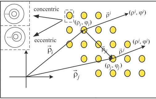
In this section, the multilayered rod forest is considered, imitating the model in [14] as an EBG structure. There are P multilayered dielectric rods and Q vias located in the plate pair. The dielectric rods are viewed as loaded ports and the vias are viewed as source ports. The locations of those radial ports are presented in global coordinate by
ρi = (ρi, ϕi), i= 1,2,3, . . . , P, P + 1, . . . , P +Q
The point in the local coordinate which is set up at the center of each radial port is presented by
ρi = (ρi, ϕi) as shown in Fig. 5. Generally, the superscript means the local coordinate and the subscript
means the global coordinate.
r
Ă
Ă
concentric
eccentric
(ρ i,ϕi)
(ρ j,ϕj) (ρ i,ϕi)
(ρ j,ϕj) ρji
r ρi
r ρj
r
ρ
ir
ρ
jFigure 5. Top view of rod forest and the global or local coordinate system.
In the rod forest, the scattered cylindrical harmonics from theith port will illuminate thejth port. It means that the scattered cylindrical harmonics bi in coordinate xioiyi is the incident cylindrical harmonicsaj in coordinate xjojyj. As discussed in Section 2, the transformation matrix Tji is applied to describe this phenomenon.
aj=Tjibi (35)
whereTjiis a (2N+ 1)∗(2N+ 1) matrix, and it can be obtained by Eqs. (27)–(29) for a regular infinite plate pair.
ForP loaded ports and Q source ports, the combined matrix of the addition theorem coefficients can be expressed as
T=
⎡ ⎢ ⎢ ⎣
T11 T12 . . . T1(P+Q)
T21 T22 . . . T2(P+Q) ..
. . .. . .. ... T(P+Q)1 T(P+Q)2 . . . T(P+Q)(P+Q)
⎤ ⎥ ⎥
⎦ (36)
To distinguish the source ports and loaded ports, the matrixT is divided into four block matrix
as:
al as
=
Tll Tls Tsl Tss
bl bs
where subscriptsandlmeans the source ports and loaded ports, respectively. As described in Section 2, the block matrix al and bl can be written as
bl=Γlal (38)
And from (37),al can be expressed as
al=Tllbl+Tlsbs (39) Substituting Eq. (39) to Eq. (38), thebl andascan be expressed as
bl = (I−ΓlTll)−1ΓlTlsbs (40) as = Tss+Tsl(I−ΓlTll)−1ΓlTlsbs (41) Through Eq. (41), the coupling between two source ports among dielectric rod forest can be calculated.
4. NUMERICAL EXAMPLES AND DISCUSSIONS
Several examples are provided to validate the accuracy and the efficiency of the proposed method in this section. The simulation results are conducted by a full-wave field simulator CST based on the finite integration technique (FIT) on a machine with 2 GHz CPU and 32 GB RAM.
O1
O O2 3
r1 r
r3 2
r1
r r3
2
x
y
x
y
φ
φ
O
ε1ε
ε3
2 ε1 ε ε
3 2
(a) (b)
Figure 6. Top view and the parameters. (a) Concentric rod. (b) Eccentric rod.
150
100
50
0
0 50 100 150 200 250 300 350
140
100
40
00 50 100 150 200 250 300 350
20 60 80 120
φ/( )o φ/( )o
SW(
σ
/
λ
)/m
2-D
SW(
σ
/
λ
)/m
2-D
(a) (b)
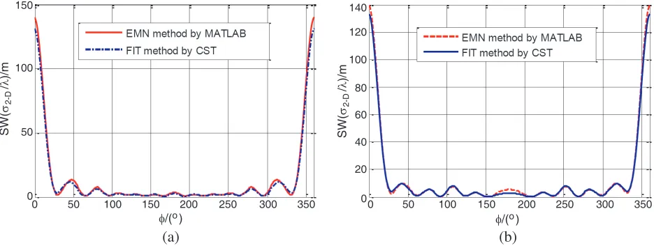
Figure 6 shows a three-layer concentric dielectric rod and a three-layer eccentric dielectric rod. The relative permittivityε1,ε2,ε3 are 2, 3, 4 and radiir1, r2,r3 are 0.1 m, 0.08 m, 0.06 m, respectively. In
Fig. 6(b), the centers of these three rodsO1,O2,O3 are (0, 0), (0.02, 0), (0.04, 0), respectively. φis the
angle between the observation point and the +x axis. The source is a plane wave traveling in the +x direction. The truncation numberN, which is described below (4), is set as 25. The scattering width (SW) at 3 GHz is applied to demonstrate the accuracy of the EMN method proposed in this article. The simulation results match well with the EMN results as shown in Fig. 7.
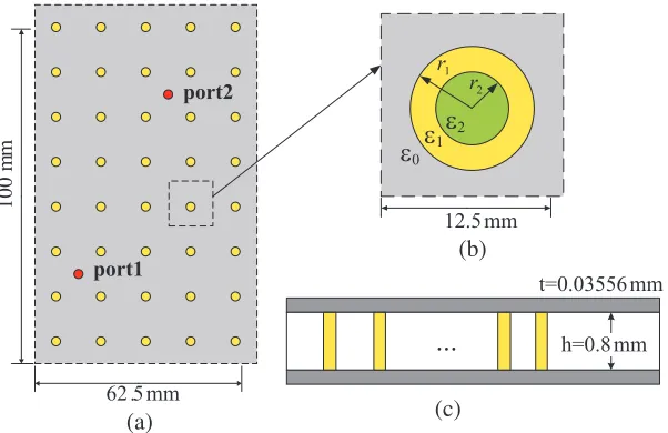
The second example is a photonic crystal power/ground layer (PCPL) with multilayered dielectric rod forest. As shown in Fig. 8, the dimensions of the PCPL structure are 62.5 ∗100 mm, and the structure is divided into 40 units on average. There are 40 two-layer dielectric rods embedded on the lossless dielectric substrate whose dielectric constant ε0 is 2.33. The radii of those two-layer concentric
rods are r1 = 2 mm, r2 = 1 mm, and the relative dielectric constant of the lossless rods are ε1 = 102, ε2 = 4.4. The rods have the same height with the parallel plate separation. The power/ground metal
plates are modeled as PEC with a thickness of 0.03556 mm. The origin of the Cartesian coordinate is located at the bottom left corner of the parallel plates, and the two vias or source ports are located at
P1 (12.5 mm, 25 mm) andP2 (25 mm, 46.5 mm).
...
t=0.03556 mm
h=0.8 mm 12.5 mm
port1
port2
62 .5 mm
100 m
m
r1
r2
ε0ε1
ε2
(a)
(b)
(c)
Figure 8. The structure of PCPL. (a) Top view. (b) Partial enlarged drawing of one unit. (c) Cross-section view.
The coupling between the source ports can be described by S21 parameter. Fig. 9 shows the
magnitude ofS21 by FIT simulator CST and the numerical results of EMN method. Great agreements
can be seen between these two methods. There are two stopbands, from 3 to 5.5 GHz and 6 to 7.5 GHz. The main discrepancies in the stopband from 3 to 5.5 GHz are caused by the spurious rapid resonances in the FIT simulator and the drawback of the time-domain solver for high-Q resonators formed by PCPL. Additional, in this example, it took about 1 minute by MATLAB code with the EMN method, while FIT simulator spent more than 20 hours.
5. CONCLUSION
Equivalent microwave network method (EMN) is proposed in this article to analyze the concentric and eccentric multilayered dielectric rods. The reflection matrix and transformation matrix are introduced into the calculation. The reflection matrix of multilayered dielectric rod is calculated and loaded to radial scattering matrix to analyze a novel EBG structure. All the numeric calculation results match well with the full-wave simulations and the EMN method is efficient and flexible for modeling PCPL structure.
REFERENCES
1. Oo, Z. Z., E. X. Liu, E. P. Li, and Y. J. Zhang, “Computing the RCS of dielectric coated objects using multilevel fast multipole algorithm: Impedance boundary condition approach,”International Conference on Computational Electromagnetics and ITS Applications, 2004, Proceedings, ICCEA, 100–103, 2004.
2. Lee, S. C., “Scattering by closely spaced parallel nonhomogeneous cylinders in an absorbing medium,”Journal of the Optical Society of America A, Vol. 28, No. 9, 1812–1819, 2011.
3. Leviatan, Y. and A. Boag, “Analysis of electromagnetic scattering from dielectrically coated conducting cylinders using a multifilament current model,” IEEE Transactions on Antennas &
Propagation, Vol. 35, No. 11, 1119–1127, 1987.
4. Barabls, M., “Scattering of a plane wave by a radially stratified tilted cylinder,” Journal of the Optical Society of America A, Vol. 4, No. 12, 2240–2248, 1987.
5. Lee, S. C. and J. A. Grzesik, “Light scattering by closely spaced parallel cylinders embedded in a semi-infinite dielectric medium,” Journal of the Optical Society of America A, Vol. 15, No. 1, 163–173, 1998.
6. Yasumoto, K., V. Jandieri, and B. Gupta, “Electromagnetic scattering by cylindrical arrays of circular rods,”IEEE Transactions on Antennas & Propagation, Vol. 59, No. 6, 312–315, 2009. 7. Kishk, A. A., R. P. Parrikar, and A. Z. Elsherbeni, “Electromagnetic scattering from an eccentric
multilayered circular cylinder,” IEEE Transactions on Antennas and Propagation, Vol. 40, No. 3, 295–303, 1992.
8. Stratigaki, L. G., “Scattering from a dielectric cylinder with multiple eccentric cylindrical dielectric inclusions,”IEE Proceedings — Microwaves Antennas and Propagation, Vol. 143, No. 6, 505–511, 1996.
9. Ioannidou, M. P., K. D. Kapsalas, and D. P. Chrissoulidis, “Electromagnetic-wave scattering by an eccentrically stratified, dielectric cylinder with multiple, eccentrically stratified, cylindrical, dielectric inclusions,” Journal of Electromagnetic Waves and Applications, Vol. 18, No. 4, 495– 516, 2004.
10. Jarem, J. M., “Rigorous coupled wave analysis of bipolar cylindrical systems: Scattering from inhomogeneous dielectric material, eccentric, composite circular cylinders,” Progress In Electromagnetics Research, Vol. 18, No. 1, 181–237, 2003.
11. Jarem, J. M., “Rigorous coupled wave theory of anisotropic, azimuthally-inhomogeneous cylindrical systems,”Journal of Electromagnetic Waves and Applications, Vol. 19, No. 7, 911–912, 2012. 12. Jarem, J. M., “Rigorous coupled wave analysis of radially and azimuthally-inhomogeneous,
13. Zhang, Y. J. and J. Fan, “A generalized multiple scattering method for dense vias with axially anisotropic modes in an arbitrarily shaped plate pair,” IEEE Transactions on Microwave Theory and Techniques, Vol. 60, No. 7, 2035–2045, 2012.
14. Tian, X., Y. J. Zhang, D. Liu, and L. Gui, “Efficient analysis of power/ground planes loaded with dielectric rods and decoupling capacitors by extended generalized multiple scattering method,”
IEEE Transactions on Electromagnetic Compatibility, Vol. 57, No. 1, 135–144, 2015.