A ‘Divide and Conquer’ Regularization Imaging Method for
Forward-Looking Scanning Radar Azimuth Super-Resolution
Ke Tan*, Wenchao Li, Yulin Huang, Qian Zhang, and Jianyu Yang
Abstract—Sparse regularization imaging method (SRIM) is an effective approach to implement azimuth super-resolution for forward-looking scanning radar. However, for the scene that contains adjacent strong targets in the continuous weak background, SRIM may destroy the structure of the scene when trying to separate the closely located targets. In this paper, a divide and conquer regularization imaging method (DC-RIM) is proposed to solve this problem. Firstly, the data are divided into two channels by the mean-variance segmentation method. Normally, we consider that the data of channel I contain strong scatterers and that the data of channel II contain weak background. Afterwards, SRIM is conducted on channel I to distinguish the targets. For the data of channel II, a region enhancement regularization method is particularly proposed to acquire a good structure of the scene by making use of two-order gradient information of the data. Finally, a good imaging result can be obtained by combining the results of two channels. Experiments based on both synthetic and real data are given to verify the effectiveness of the method.
1. INTRODUCTION
Forward-looking radar imaging is highly desirable in many applications, such as airplane navigation, automatic landing and material airdrop [1, 2]. A high-quality forward-looking image that contains clearly resolved targets as well as a well-retrieved background is not only significant for target detection and recognition, but also critical for surface mapping and scene surveillance [3]. However, conventional monostatic synthetic aperture radar (SAR) and Doppler beam sharpen (DBS) techniques cannot be used for forwarding-looking imaging due to the slight variation of Doppler frequency and symmetrical range history in forward-looking terrain [4, 5].
One simple and efficient approach for forward-looking imaging is to use scanning radar to acquire the real beam echo firstly. Then, super-resolution techniques are conducted to improve the azimuth resolution [6]. In [7], the real iterative adaptive approach (Real-IAA) was introduced to realize super-resolution for forward-looking scanning radar, which can improve the azimuth super-resolution efficiently without introducing artificial ringing. However, since there are massive inverse matrix calculation, great amount of computation time is required, which greatly restricts its application in real time application. Deconvolution is another simple and efficient technique to realize the super-resolution imaging for scanning radar [8]. However, deconvolution is an ill-posed problem, and its solution is greatly sensitive to noise.
Regularization method provides an effective approach to ease the noise sensitivity by combining a regularization term to the linear observation [9, 10]. For instance, the classical Tikhonov regularization algorithm adopts a2 norm as the punishment item to constrain the energy and stable the solution [11]. Besides, the total variation (TV) operator has advantage in retrieving the detail of the image [12].
Received 10 January 2018, Accepted 18 March 2018, Scheduled 29 March 2018 * Corresponding author: Ke Tan ([email protected]).
Recently, sparse regularization imaging method (SRIM) has drawn much attention in radar imaging area for its powerful ability in distinguishing the targets. In [13–15], the reconstruction for dominate sparse targets has been widely researched in Tomographic SAR, SAR and Inverse SAR (ISAR) imaging, and enhanced imaging results have been acquired. In the forward-looking imaging area, the lp-norm (0 < p ≤ 1) sparse constraint is adopted and exhibits extraordinary ability in resolving the closely located scatters as well as reducing the sidelobes of the scatters [16].
However, when it comes to the scene containing adjacent strong targets in the continuous background, SRIM may destroy the continuous background when it tries to separate the closely located targets due to its strong ability in concentrating the energy. Therefore, for some scenes, like a harbor berthed with ships or tanks harboured in the woods, etc., separating the targets and maintaining the outline of the scenes usually cannot be obtained simultaneously by using SRIM. This will cause great obstacles for the region-based feature extraction in scene surveillance, surface mapping, etc.
In this paper, a divide and conquer regularization imaging method (DC-RIM) is proposed to solve this problem. To process the data with distinct characteristics, the received data are firstly divided into two channels: Channel I includes the adjacent strong targets, and Channel II contains the background data. Then SRIM is conducted on Channel I to resolve the targets. As for the data of Channel II, since the background has lower SNR than the strong targets, the2norm term is more suitable for overcoming the impact of noise. However, the2norm constraint is sensitive to outliers and tends to perform heavy penalty on them, which would result in overly smoothed background. Therefore, to acquire a good structure of the scene, we propose a region enhancement regularization algorithm (RERA) on the basis of 2 norm constraint for Channel II. At last, the imaging result is obtained by combining the results of two channels. Experiments based on both synthetic and real data have been conducted to verify the effectiveness of the proposed method.
This paper is organized as follows. The signal model for forward-looking scanning radar is established in Section 2. In Section 3, the divide and conquer strategy is proposed firstly. In addition, a region enhancement regularization algorithm is proposed to process the data of background. In Section 4, experiments based on both synthetic and real data are conducted to verify the effectiveness of the proposed method. Conclusions are given in Section 5.
2. SIGNAL MODEL
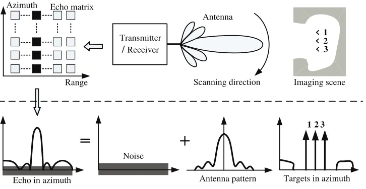
In this section, the signal model is introduced for forward-looking scanning radar (FLSR). Fig. 1 demonstrates the process of data acquisition for FLSR in which the radar antenna is sweeping the scene, and linear frequency modulation signals are transmitted and received at a certain pulse repetition rate. The echoes are recorded in a two-dimensional matrix. After range pulse compression and migration correction, the echo can be expressed as a convolution of the scattering coefficients with a convolution kernel including the antenna pattern in the angle coordinates and the sinc function in the range coordinate [17],
s(θ, r) =σ(θ, r)∗
h(θ)sinc
2B
c r
(1)
whereθdenotes the azimuth angle variable,r the range,B the bandwidth of LFM,cthe speed of light,
∗the convolution operation, s(θ, r) the output voltage of the receiver,σ(θ, r) the scattering coefficients of the targets, h(θ) the antenna pattern, and sinc2cBr the modulation function after range pulse compression.
Since we concentrate on how to improve the azimuth angle resolution, only the azimuth signal is considered. Taking the noise into account, we can write the azimuth signal as
Imaging scene
Echo in azimuth
Noise
Targets in azimuth
123
Azimuth Range Echo matrix Scanning direction Transmitter /Receiver Antenna 1 3 2 Antenna pattern
Figure 1. Illustration of the data acquisition process and azimuth single model for FLSR.
For mathematical analysis, the continuous convolution model could be discretized to a matrix vector form as follows:
s= ⎡ ⎢ ⎢ ⎢ ⎢ ⎢ ⎢ ⎣ s1 s2 s3 .. . .. . sN ⎤ ⎥ ⎥ ⎥ ⎥ ⎥ ⎥ ⎦
=Hσ+n=
⎡ ⎢ ⎢ ⎢ ⎢ ⎢ ⎢ ⎣
h1 hL · · · h2
h2 h1 . . . h3
..
. . .. ...
hL
. .. . ..
hL · · · h2 h1
⎤ ⎥ ⎥ ⎥ ⎥ ⎥ ⎥ ⎦ ⎡ ⎢ ⎢ ⎢ ⎢ ⎢ ⎢ ⎣ σ1 σ2 σ3 .. . .. . σN ⎤ ⎥ ⎥ ⎥ ⎥ ⎥ ⎥ ⎦ + ⎡ ⎢ ⎢ ⎢ ⎢ ⎢ ⎢ ⎣ n1 n2 n3 .. . .. . nN ⎤ ⎥ ⎥ ⎥ ⎥ ⎥ ⎥ ⎦ (3)
wheresrepresents the received data in one range cell,N the number of sampling points,σthe scattering coefficients to be estimated, n the noise, and H the circulant convolution operation matrix which is derived from the azimuth antenna pattern h = [h1, . . . , hL]T, where L is the length of the antenna pattern vector. A direct method to estimate σ from sis the least squares (LS) approach in which the estimator is chosen to minimize the data error
ˆ
σ = argmin σ
F(s) =s−Hσ22
(4)
Nevertheless, this result is quite sensitive to noise. In order to solve this problem, regularization methods are adopted in this paper.
3. STRATEGY AND METHOD
In radar imaging area, the sparse regularization imaging method (SRIM) has exhibited extraordinary ability in resolving the closely located scatters. However, when it comes to the scene which contains cohesive targets in the continuous background, the SRIM may deteriorate the continuous background when trying to separate the closely located targets. Therefore, the resolving ability and maintaining the outline of the scene usually cannot be obtained simultaneously. A divide and conquer regularization imaging method (DC-RIM) is proposed in this section to tackle the problem. In the first subsection, we first give a flowchart of divide and conquer strategy and elaborate the implementation details. Then a region enhancement regularization algorithm (RERA) is particularly proposed to obtain a well-retrieved background.
3.1. Divide and Conquer Imaging Strategy
Real beam echo
Output the imaging result Determine the segmentation threshold
using mean/variance segmentation method
Data of channel I
Data of channel II
Process the data using SRIM
h
T
h
T
Yes
+
Input the parameter and
β δ
Process the data using RERA
≥
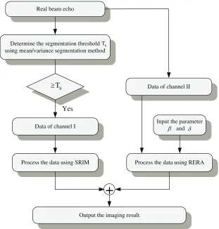
Figure 2. The flowchart of divide and conquer imaging strategy.
Step 1: Segmentation threshold value determination. The targets that we are interested in normally have the highest amplitude in the received data. Therefore, the mean/variance segmentation method can be used to detect potential strong targets. The specific steps are given as follows: Firstly, the mean value μis calculated; secondly, addκ times the standard deviation ξ to the mean value. Then the the segmentation threshold Th is obtained:
Th =μ+κξ (5)
Generally, κ takes the value between 3 to 4. The reason for the working of this method is that the pixels, whose value beyondμ+ 3ξ, can be treated as outliers in the image according to the 3ξprinciple in statistic, and this is exactly what the characteristic of sparse strong targets acts in the echo.
Step 2: Data separation. According to the segmentation threshold value obtained in step 1, the strong targets can be firstly extracted from the echo. Next, to avoid damage of the antenna pattern modulation, half beamwidth is extended to both sides of the detected area in azimuth, and the result is treated as the data of Channel I. Then, the left echo is considered as the data of Channel II. However, since the truncation after extraction would destroy the continuity of the background and might cause the unwanted artifacts after processing, the data of the detected area would be compensated to Channel II before conducting the corresponding regularization algorithm.
Step 3: Data processing. After dividing the data, the imaging problem will be conquered by implementing SRIM and RERA on the data of Channel I and Channel II, respectively. RERA will be particularly introduced in the next subsection.
corresponding to the detected area are treated as targets and should be eliminated. Then the result of DC-RIM can be obtained by combining the processed results together.
3.2. The Region Enhancement Regularization Imaging Algorithm
The objective of regularization for forward-looking imaging is to estimate targets scattering coefficients
σ from the received datasas accurately as possible. Given sandH, the estimated σˆ can be obtained by minimizing the following objective function
F(σ) =s−Hσ22+λΦ (σ) (6) The first part of F(σ) is the data fidelity term which measures the fitness of the estimation with the observed data. The second part is the regularization term, which is utilized to incorporate the prior information about the estimator to constrain the solution. The regularization parameterλcontrols the relative weight of the two terms.
Normally, different regularization operators display diverse performances. For instance, the sparse regularization has strong ability in distinguishing the strong targets. Other than that, the Tikhonov regularization operator is pretty robust to the noise because of its 2 norm constraint. As for the data of Channel II, since the background has lower SNR than the strong targets in Channel I, the 2 norm constraint is suitable for overcoming the impact of noise, whereas the 2 norm constraint is too sensitive to the outliers and tends to perform heavy penalty to the large values, which would result in overly smoothed background. Therefore, to acquire a well-behaved structure of the background, we propose a region enhancement regularization algorithm (RERA) by making use of the two-order gradient information of the scene.
F(σ) =s−Hσ22+λ1Lσ22+λ2∇xxσ1 (7) where Lσ2 stands for the 2 norm regularizer; the common choices for L are the identity or matrix approximating the derivative operator; λ1 and λ2 are the parameters which control the weights of two regularizers respectively;∇xxσ stands for a two-order gradient operator ofσ, which is defined as
∇xxσ= (˜σ1,· · ·,˜σi· · ·,σN˜ )T, σi˜ = σi+1+σi−1−2σi (8) where σi−1, σi and σi+1 are the i−1th,ith and i+ 1th elements of σ, respectively. The second-order gradient operator can efficiently measure the variation of the gradient, and the 1 operator would concentrate the energy on large gradient values, which can efficiently enhance the edge structure of the scene and retrieve a well-preserved outline of the background. Then the estimate σˆ is given by
ˆ
σ = argmin σ
F(σ) =s−Hσ22+λ1Lσ22+λ2∇xxσ1
(9)
Through minimizing the newly formulated objective function, the obtained solution can maintain the continuity of the original scene and construct fine structures of the scene. When determining the regularization parameters, a uniform λ can be firstly calculated for λ1 and λ2 through the L-curve method [18]. Afterwards, a gradient entropy scale factorρ is used to modify the parameterλ2, which is
λ2=ρλ (10)
with
ρ= ςcell
ςaverage (11)
where ςcell and ςaverage are the gradient entropies of the processed range bin and the whole echo, respectively
ςcell =−
Mc
q=0
Pc(q)log2Pc(q), ςwhole=−
Mw
q=0
Pw(q)log2Pw(q) (12)
indicates that if the gradient variation of the current range cell is larger than the global gradient variation, the penalty for the two-order gradient term should be stronger than the average penalty and vice versa.
As to the solution of the optimal problem obtained by Equation (9), since the1 operator is non-differential and the direction solution unaccessible, the two-order gradient regularization operator can be modified by the following smooth approximation
∇xxσ1 =
N−1
i=2
(˜σi)2+ε
1/2
(13)
where ε≥0 is a small constant introduced to solve the non-differentiability of the 1 operator. Then the idea of an accelerated iterative shrinkage/thresholding algorithm is adopted in this paper in order to solve the obtained convex optimal problem [19]. Moreover, this fast algorithm will greatly facilitate the engineering application of the proposed method through shortening the computation time of the proposed method with almost no performance loss. Firstly, the gradient of the objective function is calculated as
∇F(σ) =HT(Hσ−s) +λ1LTLσ+λ2diag
|σi˜|2+ε
−1
2σ
(14)
where diag (·) is the diagonal matrix with elements in the bracket as its diagonal. Following the gradient direction in theN dimensional data space, the basic iterative formula to search the optimal solution is given by
σk+1 =ψ(σk) =δ{σk−α∇F(σk)} (15)
which is
σk+1=δ
σk−α
HT (Hσk−s) +λ1LTLσk+λ2diag
|(˜σk)i|2+ε
−1
2σ
k
(16)
where σk is the iterative result after k iterations, α the step size which is confined to be smaller than 2/HTHto ensure the convergence. δ:RN →RN is the shrinkage/thresholding operator defined by
δ(x) = [δ(x1),· · · ,δ(xi),· · · ,δ(xN)], where
δ(xi) =
0 , |xi| ≤δ
xi−δsgn(xi) , otherwise (17)
Then the implementation steps to obtain the optimal solution of Equation (9) are given as follows:
Input: The parametersα and δ for the iterative formula Equation (16)
Initial Step: Take σ0 = s, compute the first two iterative results through Equation (16),
σ1 =ψ(σ0),σ2 =ψ(σ1) and the first two iterative vectors g1=σ1−σ0 and g2 =σ2−σ1
Repeat
Compute the extrapolation step size
αk= g
k· gk−1
g
k−1· gk−1 0< αk <1
Calculate the prediction point
yk+1=σk+αk(σk−σk−1)
Compute the next iterative result σk+1 with obtained predicted point yk+1 through Eq. (16),
σk+1 =ψ(yk+1)
Update the iterative vector gk+1=ψ(yk+1)−yk+1
Untilconvergence
Outputσk+1
4. EXPERIMENTAL RESULTS
4.1. Two Dimensional Scene Simulation
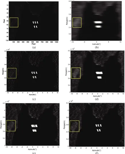
The simulation scene is shown in Figure 3(a), wherein several ships are berthed in a harbor, and there is a playground located aside the coast. Some related simulation parameters are set as follows: the velocity of the platform is 50 m/s; the pulse repetition frequency is 2000 Hz; the 3 dB width of the antenna pattern is 3◦. The radar antenna scans from −10◦ to 10◦ with an antenna scanning speed 70◦/s. In addition, the relative phases of the targets are set to zero for the sake of better exhibition.
Figure 3(b) displays the real beam echo of scanning radar after range migration correction, of which the signal to noise ratio (SNR) equals 20 dB. We can tell that the ships cannot be resolved due to the low azimuth resolution. The SRIM introduced in [16] is firstly conducted on the echo, and the sparse norm is chosen as p = 0.8 as suggested by the author. The discrepancy criterion is used to stop the iterations and so do the other methods [7]. The result of SRIM is demonstrated in Figure 3(c), from which it can be observed that the targets are distinguished completely. Nevertheless, the background is granulated, and the structure of the playground has been seriously destroyed. Figure 3(d) displays the result of Tikhonov method [9], from which it can be told that the scene tends to be overly smoothed and that the ships are barely separated. Then the proposed DC-RIM is conducted, and the segmentation parameter κ is set as 4. The input parameters for the data of Channel II are initialized asβ = 1 and
δ= 0.5, and the result of RERA is displayed in Figure 3(d). It can be observed that the playground is enhanced, and the outline of the scene is much clearer than Tikhonov.
To further demonstrate the reconstruction of the background, especially the distinct playground, structure similarity (SSIM) [20] is used to measure the quality of the recovered playground. The larger the value is, the closer the result will approach the original scene. The computation of the SSIM is confined within a rectangle area, which is indicated in Figure 3 by yellow rectangle. The SSIMs of SRIM, Tikhonov and RERA are calculated to be 0.2076, 0.4550 and 0.5461, respectively. It can be seen that RERA can retrieve the structure of the background better than the other two methods. Finally, the DC-RIM is conducted, and the result is demonstrated in Figure 3(f). It can be observed that not only all the ships are separated thoroughly, but also the structure of the background is well retrieved.
Next, we compare the performance of different methods in various SNR cases. Relative error (ReErr) is used to measure the energy difference between the imaging result and the original scene [20]. In addition, the performance improvement ratio (PIR) is defined to evaluate the extent of the performance improvement by DC-RIM compared with SRIM
PIRSRIM=|
ReErrDC−RIM−ReErrSRIM| ReErrSRIM
(18)
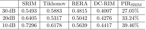
The comparisons of the ReErr in different SNR cases are illustrated in Table 2. In the case of SNR = 30 dB, Tikhonov method has the largest ReErr due to the lack of ability to recover the detail of the scene. In the case of SNR = 20 dB and SNR = 10 dB, the ReErrs of SRIM are the lowest, because the background would be greatly destroyed in low SNR cases when the SRIM tried to separate the closely located boats. Compared with other regularization methods, the proposed DC-RIM has the lowest ReErr in all cases, which shows that the proposed method can effectively decrease the imaging error and reconstruct the original scene more accurately. Moreover, the performance improvement factor PIRSRIM is getting larger while the SNR is decreasing, which indicates that the DC-RIM has a more prominent advantage in the low SNR situation than SRIM.
Table 1. The comparison of ReErr in different SNR cases.
SRIM Tikhonov RERA DC-RIM PIRSRIM
30 dB 0.5493 0.5883 0.4815 0.4007 27.05%
20dB 0.6405 0.5317 0.5042 0.4276 33.24%
(a) (b)
(c) (d)
(e) (f)
Figure 3. Result of two dimensional scene simulation: (a) Original scene. (b) Real beam echo after range migration correction. (c) Result of SRIM. (d) Result of Tikhonov. (e) Result of RERA. (f) Result of DC-RIM.
4.2. Real Data Processing
Table 2. Experiment parameters.
Parameters Values
Carrier frequency 30.75 GHz
Band width 40 MHz
Pulse duration 2µs
Pulse repetition frequency(PRF) 4000 Hz Antenna scanning velocity 60◦/s
Antenna scanning area ±33◦
Main-lobe bean width 4◦
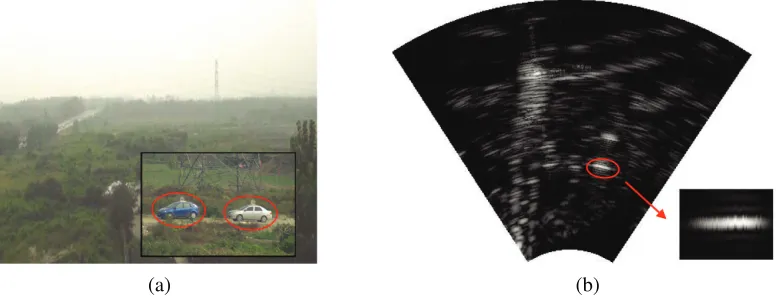
forward-looking region. The experiment parameters are illustrated in Table 2. Figure 4(a) displays the experiment scenario in which there are two crossed roads in the scene, and most parts of the roads are shielded by the bush and cannot be revealed in the optical image. Two corner reflectors are settled on the roof of two cars, which are parked in the same range. The centroids of the two corner reflectors are 7 m apart, and the targets are illustrated in the mini-picture in the right of Figure 4(a). Since the distance between the targets and the radar is 310 m, the angle space between the two reflectors is approximated to be 1.3◦. The echo for the scanning radar with range compression is shown in Figure 4(b), from which we can tell the outline of the roads. The brightest area that is circled out by an ellipse is where the two corner reflectors are located. Nevertheless, since the two reflectors are within one antenna beamwidth, they cannot be resolved.
(a) (b)
Figure 4. Experiment scenario and echo: (a) Optical scenario. (b) Echo after range compression.
(a) (b)
(c) (d)
Figure 5. Experiment results for the real data. (a) Result of SRIM. (b) Result of Tikhonov. (c) Result of RERA. (d) Result of DC-RIM.
5. CONCLUSION
In this paper, we have proposed a divide and conquer regularization imaging method for forward-looking scanning radar. For the scenes that contain adjacent strong targets in the continuous background, resolving the closely located targets and maintaining a good outline of the scene usually cannot be obtained simultaneously. Our proposed method firstly divides the echo into two channels. Then SRIM is conducted on channel I to resolve the targets, and a newly proposed region enhancement algorithm is preformed on channel II to retrieve a good outline of the scene. Finally, the results of the two channels are combined, and then the final imaging result is obtained. Simulations and real data experiments have verified the advantage of proposed method compared with the traditional regularization imaging methods.
REFERENCES
1. Ma, C., H. Gu, W. Su, and C. Li, “Bistatic forward-looking synthetic aperture radar imaging based on the modified Loffeld’s bistatic formula,”Progress In Electromagnetics Research M, Vol. 36, 117– 129, 2014.
2. Liu, C., S. Zhang, C. Dai, and J. Zhou, “Focusing translational variant bistatic forward-looking SAR data based on two-dimensional non-uniform fft,” Progress In Electromagnetics Research M, Vol. 37, 1–10, 2014.
3. Zhang, Y., Y. Huang, Y. Zha, and J. Yang, “Superresolution imaging for forward-looking scanning radar with generalized gaussian constraint,” Progress In Electromagnetics Research M, Vol. 46, 1–10, 2016.
5. Feng, D., D. X. An, and X.-T. Huang, “Image formation using fast factorized backprojection based on sub-aperture and sub-image for general bistatic forward-looking sar with arbitrary motion,” Progress In Electromagnetics Research B, Vol. 74, 141–153, 2017.
6. Dropkin, H. and C. Ly, “Superresolution for scanning antenna,” 1997 IEEE National Radar Conference, 306–308, IEEE, 1997.
7. Zhang, Y., Y. Zhang, W. Li, Y. Huang, and J. Yang, “Super-resolution surface mapping for scanning radar: Inverse filtering based on the fast iterative adaptive approach,” IEEE Transactions on Geoscience and Remote Sensing, Vol. 56, No. 1, 127–144, 2017.
8. Zha, Y., Y. Huang, and J. Yang, “An iterative shrinkage deconvolution for angular superresolution imaging in forward-looking scanning radar,” Progress In Electromagnetics Research B, Vol. 65, 35–48, 2016.
9. Golub, G. H., P. C. Hansen, and D. P. O’Leary, “Tikhonov regularization and total least squares,” SIAM Journal on Matrix Analysis and Applications, Vol. 21, No. 1, 185–194, 1999.
10. Moulin, P., “A wavelet regularization method for diffuse radar-target imaging and speckle-noise reduction,”Journal of Mathematical Imaging and Vision, Vol. 3, No. 1, 123–134, 1993.
11. Zhang, X., E. Y. Lam, E. X. Wu, and K. K. Wong, “Application of Tikhonov regularization to super-resolution reconstruction of brain mri images,” Medical Imaging and Informatics, 51–56, 2008.
12. Liu, L., W. Huang, and C. Wang, “Texture image prior for SAR image super resolution based on total variation regularization using split Bregman iteration,” International Journal of Remote Sensing, Vol. 38, No. 20, 5673–5687, 2017.
13. Zhu, X. X. and R. Bamler, “Tomographic sar inversion by l1-norm regularization — The compressive sensing approach,” IEEE Transactions on Geoscience and Remote Sensing, Vol. 48, No. 10, 3839–3846, 2010.
14. Wei, S.-J., X.-L. Zhang, J. Shi, and G. Xiang, “Sparse reconstruction for SAR imaging based on compressed sensing,” Progress In Electromagnetics Research, Vol. 109, 63–81, 2010.
15. Zhang, L., M. Xing, C.-W. Qiu, J. Li, and Z. Bao, “Achieving higher resolution ISAR imaging with limited pulses via compressed sampling,” IEEE Geoscience and Remote Sensing Letters, Vol. 6, No. 3, 567–571, 2009.
16. Chen, H. M., M. Li, Z. Wang, Y. Lu, P. Zhang, and Y. Wu, “Sparse super-resolution imaging for airborne single channel forward-looking radar in expanded beam space via lp regularisation,” Electronics Letters, Vol. 51, No. 11, 863–865, 2015.
17. Guan, J., J. Yang, Y. Huang, and W. Li, “Maximum a posteriori-based angular superresolution for scanning radar imaging,”IEEE Transactions on Aerospace and Electronic Systems, Vol. 50, No. 3, 2389–2398, 2014.
18. Hansen, P. C. and D. P. O’Leary, “The use of the l-curve in the regularization of discrete ill-posed problems,” SIAM Journal on Scientific Computing, Vol. 14, No. 6, 1487–1503, 1993.
19. Tan, K., W. Li, Y. Huang, and J. Yang, “Angular resolution enhancement of real-beam scanning radar base on accelerated iterative shinkage/thresholding algorithm,” 2016 IEEE International Geoscience and Remote Sensing Symposium (IGARSS), 929–932, IEEE, 2016.