Salient Pole Synchronous Generator Optimization by Combined
Application of Slot Skew and Damper Winding Pitch Methods
Ante Elez1, *, Marijan PetriniC1, Miroslav PetriniC1, Babak Vaseghi2, and Alireza Abasian2
Abstract—Slot skew is applied as a method to increase the armature winding voltage waveform quality of synchronous hydro generators. Skew that matches the region of one slot pitch can effectively damp stator slot harmonics. However, achieving this condition can be difficult in some manufacturing cases, especially for the machines with greater axial length. That is why other methods are commonly used to increase the voltage waveform quality of large hydro generators. One such method is based on the damper winding slot pitch choice which ensures reduction of stator slot harmonics from the main magnetic field. Appropriate placement of damper bars over the pole shoe does not represent a significant technological problem and is much simpler to manufacture in compare with the slot skew or the fractional armature winding methods. The downside of damper slot pitch adjustment method is the damper bar currents incensement in steady state condition of the generator, which increases damper winding losses and also the rotor temperature. In order to decrease damper winding current for long term operation and enable the generator pole shoe design with smaller cross section damper bars, a combination of damper slot pitch and partial slot skew can be utilized. This paper gives insight on consequences that can occur for voltage waveform if slot skew does not not fully match the stator slot pitch and the advantages of above mentioned combined method for the design optimization of salient pole synchronous generator.
1. INTRODUCTION
Modern electrical generators need to satisfy different requirements among which the most prominent ones are voltage waveform quality, noise and vibration levels which are defined in tenders and measured on generator commissioning. All these requirements need to be met, while maintaining generator efficiency level. When designing a new generator such tasks are formidable and even harder to achieve in cases of generator refurbishment, where for further exploitation, parts of the old machine are kept in place [1–4].
Few methods can be used to achieve better voltage waveform, while maintaining noise and vibrations at satisfactory levels. Stator slots number, winding arrangement, slot skew and damper bar pitch can all affect the voltage waveform quality, but each has its own limitations and downsides [5–7].
The number of stator slots choices is limited due to the winding arrangement, dimensional restrictions and mechanical stiffness requirements of stator. Winding with fractional number of conductors per pole and phase has significant number of winding couplings and is more complicated to assemble [8–10].
Electromagnetically and mechanically, slot skew is one of the most effective methods to reduce the level of voltage waveform higher harmonics, noise and vibrations [1–18]. However in cases of large generators, slot skew is usually considered as a last resort method, due to technological problems such as additional stacking procedures and precision bending of the stator winding bars.
Received 5 July 2018, Accepted 4 September 2018, Scheduled 13 September 2018
* Corresponding author: Ante Elez ([email protected]).
82 Elez et al.
The main purpose of the damper winding is to protect the machine components in non-regular situations such as asymmetric load or short circuit condition. If the damper winding is only used for this purpose, the slot pitch is usually chosen to be the same as the stator slot pitch. This ensures that the slot magnetic field harmonics do not induce currents in damper winding (criteria of the smallest damper bar losses in steady state operation) [4, 14, 19].
Damper winding with the same pitch as the stator slots can be used to improve the voltage waveform if the generator has a whole number of stator slots per pole and phase. A positive effect can be achieved by shifting the damper bars over the pole shoe circumference [20, 21]. However, using this method solely does not always lead to a satisfactory quality of voltage waveform and is not practically applicable when dealing with stator which has fractional number of slots per pole and phase.
If the pitch of stator and damper slots are equal, improvement of voltage waveform can be achieved by slot skew method. To fully damp the slot harmonics, skew needs to be of the same pitch as the stator and damper winding slot pitch. Such a skew can be significant in angle size and therefore causes the above mentioned manufacturing problems [15, 16, 18].
Damper bar slot pitch can be reduced in such a way that damper bar currents actively suppress slot harmonics and improve voltage waveform. This comes at the cost of increased losses and temperature of the rotor. In such situations slot skew is not required to improve voltage waveform, but can significantly reduce currents and ohmic losses of the damper bars [9, 19, 22]. As skew angle in this case does not need to match stator slot pitch, it can be significantly shorter which leads to simpler manufacturing of stator.
To investigate how the level of stator slot skew affects the damper bar currents and how damper bar pitch affects the line voltage waveform, a finite element method (FEM) analysis was performed on a 83.5 MVA, 44 pole generator. Description of the performed analysis and related findings are presented in next sections.
2. NUMERICAL METHODS TO CALCULATE EFFECTS OF THE SLOT SKEW
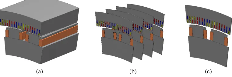
Three finite element method modelling approaches can be used to determine the effects of the slot skew on the voltage waveform and damper bar currents. Direct approach requires creating and using a 3D FEM model as can be observed in Fig. 1(a) [23]. Such simulations are computationally very demanding, long lasting and applicable mainly when analysing segment of one or two poles of the machine. That is why they are generally used for qualitative research.
In semi-direct approach a multi-slice 2D or so called 2.5D model is used [5, 13, 17, 22, 23]. In such a modelling a machine is axially divided into equal length segments as can be observed in Fig. 1(b). Each segment is magnetically represented with a 2D model, and has a geometry that is shifted in angle with relation to other segments.
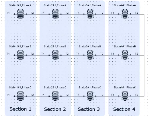
Angle shift of each segment is determined based on the slot skew value. All of the segments conductors are electrically interconnected, so a link between 2D model segments is achieved as can be
(b)
(a) (c)
Figure 2. Electrical connections between cross sections of the multi-slice 2D FEM model.
observed in Fig. 2. Results precision and computational demand of such a model depend on the number of 2D slices.
In indirect approach a regular single-slice 2D model for electromagnetic calculations is used. Acquired results using a model like this is corresponding to no slot skew condition. In order to determine voltage waveforms and damper bar currents that match the situation of a slot skew, numerical results need to be processed by additional analytical calculation [1, 13, 22]. Such an indirect calculation approach is the fastest and easiest to compute, but with lower accuracy of the results than the other two FEM calculation methods.
2.1. Optimal Number of Cross Section Segments of the Multi-Slice 2D Model FEM Simulation
When dealing with skew effect analysis, the segments number of a multi-slice 2D model can greatly affect the results accuracy. In order to identify the required minimal number of the model axial divisions to adequately calculate damper bar currents, a number of FEM simulations was conducted. A situation of the machine with 25% pitch difference between stator and damper bar slots was chosen for this analysis, because in this situation the slot skew can greatly affect the damper bar currents. Main data of the generator used for this analysis are presented in Table 1.
Total of 7 different models are analysed, in which the number of axial slices in them varies from 1 (single-slice 2D model) to 7. Table 2 shows the main results of the damper bar calculations.
In Table 2, N CS denotes the cross sections number used in the multi-slice 2D model simulation;
Table 1. Fundamental data of the generator.
Data Marking Unit Value
Rated power Sn kVA 83500
Rated voltage Un V 10500
Number of poles 2p - 44
Diameter of stator bore D mm 8000
Minimal air gap width δ0 mm 19.5
84 Elez et al.
Table 2. Effect of the number of axial cross sections on damper bar currents and losses.
N CS 1 2 3 4 5 6 7 ∞
Imax (A) 343.4 148.1 122.9 116.7 114.1 112.8 112.0 109.8
Imean (A) 180.5 93.6 70.8 66.6 65.0 64.2 63.7 62.4
Γmax (A/mm2) 17.49 7.54 6.26 5.94 5.81 5.74 5.70 5.59
Γmean (A/mm2) 9.19 4.77 3.61 3.39 3.31 3.27 3.24 3.18
P DW (W) 2733 812 477 423 403 393 387 372
P DW/P DW1 (%) 100.0 29.7 17.5 15.4 14.7 14.4 14.2 13.6
Imax denotes the rms current value of the most loaded damper bar of the pole; Imean is the mean rms
current value of all the damper bars; Γmax is the current density of the most loaded damper bar of the
pole; Γmean is the mean current density value of all the damper bars; P DW denotes the total damper
bar losses; P DW/P DW1 is the damper bar loss percentage ratio of NCS cross sectioned and a single sectioned (2D) model.
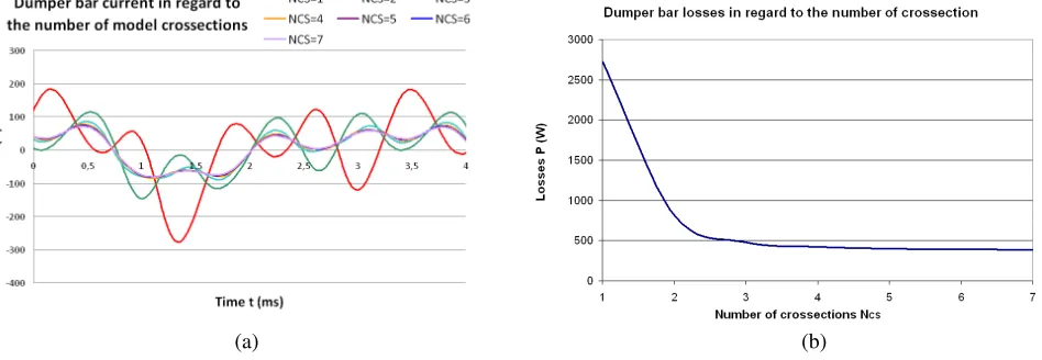
The last column of the table (where N CS = ∞) shows extrapolated results that correspond to infinite number of model cross sections, i.e., the smooth skew of a stator slot. The results show that values of damper bar currents are severely affected by a slot skew. With a slot skew that matches 75% of the stator slot pitch, damper bar currents value can be decreased by 3 times and ohm losses by 7 times. The accuracy of damper bar currents calculation increases drastically with the number of used cross sections of the FEM model.
The results show that for the model composed of only 2 cross sections, the damper bar currents values deviate over 30% from the continuous slot skew condition. With 3 cross sections this difference falls under 10%, and with 5 or higher number of cascading cross sections bar currents values differ in less than 4% from the continuous slot skew currents. Effect of increasing multi-slice 2D model cross section segments on the damper bar current and ohm loss calculation value can be observed in Fig. 3.
(b) (a)
Figure 3. Effect of increasing multi-slice 2D model cross section segments on: (a) the damper bar current, and (b) ohm loss calculation value.
2.2. Method to Determine Slot Skew Effect on Damper Bar Currents by Use of the 2D FEM Model
skew consideration. The method based on the single-slice 2D FEM model enables the determination of damper bar currents for arbitrary slot skew on the basis of the results of only one FEM calculation.
Analytical process to determine slot skew effect on the damper bar currents comprises the following steps:
(i) Waveform of each damper bar current, calculated by means of the single-slice 2D FEM model, for the non-skewed stator slot design, needs to be decomposed to harmonics, by means of the Fourier analysis.
(ii) For each harmonicν a skew factor ξskν is determined which can be obtained from Eq. (1) for any
desired slot skew s(s= 1 equals slot skew of one stator slot pitch). In this expression τp and τs
represent pole pitch and generator stator slot pitch, respectively.
ξskν =
sin (
ν.s.τsτpπ2 )
ν.s.τsτpπ2 (1)
(iii) The current harmonics amplitudes for the generator with slot skew Iskν are calculated based on
current harmonic amplitudes of a non-skewed waveform Iν and a skew factor ξskν which can be
obtained from Eq. (2):
Iskν =ξskν ×Iν (A) (2)
(iv) Waveform of each damper bar current is reconstructed by summation of electrical current harmonics with the amplitudesIskν which match the slot skew state.
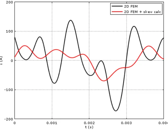
Effect of the described procedure on one of the damper bar currents is visually presented in Fig. 4. Depicted current matches the skew of 75% stator slot pitch (s= 0.75).
Figure 4. Waveform of damper bar current determined on the basis of the single-slice 2D FEM model: Current before (black) and after (red) the skew effect calculation.
2.3. Comparison of Results Obtained by Multi-Slice and Single Slice 2D FEM Model
86 Elez et al.
(b)
(a) (c) (d)
(f)
(e) (g) (h)
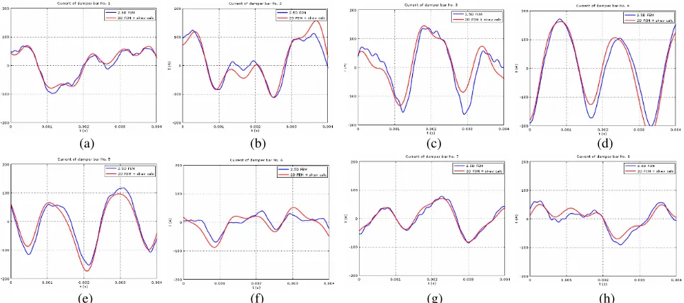
Figure 5. Comparison of damper bar current waveforms calculated by means of multi-slice 2D (blue) and single-slice 2D (red) modelling method for one pole of the generator for different number of damper bar: (a) 1, (b) 2, (c) 3, (d) 4, (e) 5, (f) 6, (g) 7, (h) 8.
Visual comparison of the damper bar current waveforms is presented in Fig. 5, while numeric rms values of currents and damper winding losses are given in Table 3. It can be observed that the calculated damper bar currents with multi-slice 2D and single-slice 2D have similar waveforms and current distributions across the damper bars of one pole. Mean difference in rms values of these currents is 5%, and final difference in losses is about 12%.
Table 3. Difference in damper bar currents obtained by single-slice and multi-slice 2D FEM method.
Damper bar 1 2 3 4 5 6 7 8 P DW (W)
I2,5D (A) 51.5 70.4 93.5 114.8 80.8 26.0 47.2 39.7 417
I2D (A) 51.7 66.7 82.7 109.8 77.8 33.4 43.9 33.4 372
∆2,5D−2D (%) −0.4 5.5 13.1 4.6 3.9 −22.2 7.5 18.9 12.1
3. EFFECT OF THE SLOT SKEW ON DAMPER BAR CURRENTS
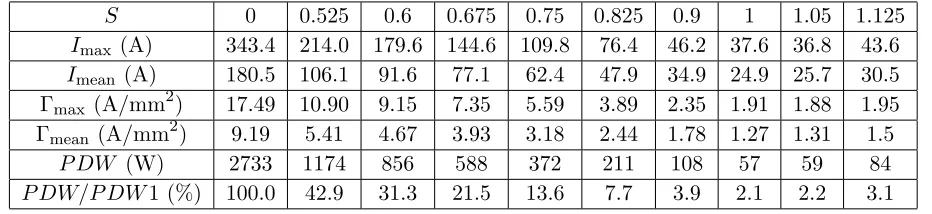
Analyses of multi-slice 2D and single-slice 2D FEM calculations showed that the slot skew which matches full stator slot pitch significantly reduces damper bar currents. In order to determine how different values of the skew impact the damper bar currents, analysis was performed for a number of different slot skews for which the results can be observed in Table 4 and Fig. 6. Calculations were conducted based on single-slice 2D FEM simulation results, with the analytic method described in Section 2.2.
(b) (a)
Figure 6. Effect of increasing the stator slot skew on: (a) the damper bar current, and (b) ohm losses.
Table 4. Effect of the stator slot skew on damper bar currents and losses.
S 0 0.525 0.6 0.675 0.75 0.825 0.9 1 1.05 1.125
Imax (A) 343.4 214.0 179.6 144.6 109.8 76.4 46.2 37.6 36.8 43.6
Imean (A) 180.5 106.1 91.6 77.1 62.4 47.9 34.9 24.9 25.7 30.5
Γmax (A/mm2) 17.49 10.90 9.15 7.35 5.59 3.89 2.35 1.91 1.88 1.95
Γmean (A/mm2) 9.19 5.41 4.67 3.93 3.18 2.44 1.78 1.27 1.31 1.5
P DW (W) 2733 1174 856 588 372 211 108 57 59 84
P DW/P DW1 (%) 100.0 42.9 31.3 21.5 13.6 7.7 3.9 2.1 2.2 3.1
4. EFFECT OF THE SLOT SKEW ON VOLTAGE WAVEFORM
Both slot skew and configuration of damper bars can enhance the quality of generator line voltage waveform. To show how these methods affect line voltage when being applied independently and simultaneously, different calculations were performed. Voltage waveform was determined for a number of different slot skews and with respect to the following damper bar arrangements:
(i) damper bars placed symmetrically in regard to the pole central line, with pitch equal to the stator slots pitch,
(ii) damper bars placed with a shift in regard to the pole central line, and a pitch that is equal to the stator slots pitch,
(iii) damper bars placed symmetrically in regard to the pole central line, with a shorter pitch than the stator slots pitch.
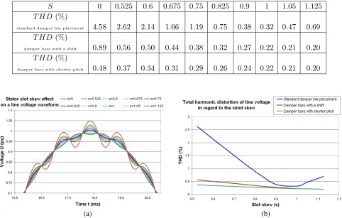
In order to evaluate the quality of voltage waveform, the total harmonic distortion (THD) was calculated for each analysed situation. Table 5 contains numerical data, while graphical representation can be observed in Fig. 7.
For all of the analysed situations the total harmonic distortion of generator is smaller than 5% which is in compliance with the requirements of IEC 60034-1 standard. By only implementing the slot skew, THD value of line voltage can be reduced to the level of less than 1%. However, to accomplish such line voltage quality, skew value needs to be higher than 80% of the stator slot pitch.
88 Elez et al.
Table 5. Effect of the stator slot skew on the line voltage total harmonic distortion (THD).
S 0 0.525 0.6 0.675 0.75 0.825 0.9 1 1.05 1.125
T HD (%)
standard damper bar placement 4.58 2.62 2.14 1.66 1.19 0.75 0.38 0.32 0.47 0.69
T HD (%)
damper bars with a shift 0.89 0.56 0.50 0.44 0.38 0.32 0.27 0.22 0.21 0.20
T HD (%)
damper bars with shorter pitch 0.48 0.37 0.34 0.31 0.29 0.26 0.24 0.22 0.21 0.20
(b) (a)
Figure 7. Effect of increasing the stator slot skew on: (a) the line voltage waveform, and (b) total harmonic distortion.
5. CONCLUSION
The numerical calculation results of slot skew impact on the voltage waveform and damper bar currents of a 44 pole 83.5 MVA, 10.5 kV synchronous vertical hydro generator have been analysed. Details of the single-slice 2D finite element method based calculation to determine slot skew effect on the generator damper bar currents and losses have been described, and the results have been compared to the multi-slice 2D finite element method calculations.
By applying a slot skew, damper bar currents can be reduced by approximately 2.6 times and damper bar losses by approximately 7 times. Total harmonic distortion of line voltage can be reduced to less than 1% with either the slot skew or the damper bar arrangement. Combination of both methods leads to even higher quality of voltage waveform, and the reduction of damper winding losses.
REFERENCES
1. Pyrhonen, J., T. Jokinen, and V. Hrabovcova,Design of Rotating Electrical Machines, John Wiley & Sons, 2013.
3. Ma, X., Q. Lu, X. Huang, and Y. Ye, “Optimization and performance of linear pm-assisted reluctance synchronous machine for wave energy generation,” 2017 20th International Conference on Electrical Machines and Systems (ICEMS), IEEE, 1–6, 2017.
4. Vaseghi, B., N. Takorabet, and F. Meibody-Tabar, “Transient finite element analysis of induction machines with stator winding turn fault,” Progress In Electromagnetics Research, Vol. 95, 1–18, 2009.
5. Williamson, S., T. J. Flack, and A. F. Volschenk, “Representation of skew in time-stepped two-dimensional finite-element models of electrical machines,” IEEE Transactions on Industry Applications, Vol. 31, No. 5, 1009–1015, 1995.
6. Wang, X., T. D. Strous, D. Lahaye, H. Polinder, and J. A. Ferreira, “Computationally efficient calculation of skew effects in brushless doubly-fed induction machines,” IET Electric Power Applications, Vol. 11, No. 3, 303–311, 2017.
7. Petrov, I., P. Ponomarev, Y. Alexandrova, J. Pyrh¨onen, et al., “Unequal teeth widths for torque ripple reduction in permanent magnet synchronous machines with fractional-slot non-overlapping windings,”IEEE Transactions on Magnetics, 2015.
8. Zhan, Y., A. M. Knight, and N. Stranges, “Multislice inter-bar model for large synchronous machines with skewed stator slots,” IEEE Transactions on Magnetics, Vol. 45, No. 3, 1800–1803, 2009.
9. Bomela, X. B. and M. J. Kamper, “Effect of stator chording and rotor skewing on performance of reluctance synchronous machine,”IEEE Transactions on Industry Applications, Vol. 38, No. 1, 91–100, 2002.
10. Neubauer, M., H. Neudorfer, and M. Schr¨odl, “In uence of the rotor optimization of an interior permanent magnet synchronous generator on the short circuit behavior,”2016 XXII International Conference on Electrical Machines (ICEM), IEEE, 1828–1834, 2016.
11. Karmaker, H. and A. M. Knight, “Investigation and simulation of fields in large salient-pole synchronous machines with skewed stator slots,”IEEE Transactions on Energy Conversion, Vol. 20, No. 3, 604–610, 2005.
12. Jagiela, M., E. Mendrela, and P. Gottipati, “Investigation on a choice of stator slot skew angle in brushless PM machines,”Electrical Engineering, Vol. 95, No. 3, 209–219, 2013.
13. Knight, A. M., S. Troitskaia, N. Stranges, and A. Merkhouf, “Analysis of large synchronous machines with axial skew, part 1: flux density and open-circuit voltage harmonics,” IET Electric Power Applications, Vol. 3, No. 5, 389–397, 2009.
14. Koo, M.-M., J.-Y. Choi, K. Hong, and K. Lee, “Comparative analysis of eddy-current loss in permanent magnet synchronous machine considering PM shape and skew effect using 3-d FEA,” IEEE Transactions on Magnetics, Vol. 51, No. 11, 1–4, 2015.
15. Nuzzo, S., M. Galea, C. Gerada, and N. Brown, “A fast method for modeling skew and its effects in salient-pole synchronous generators,”IEEE Transactions on Industrial Electronics, Vol. 64, No. 10, 7679–7688, 2017.
16. Flankl, M., A. T¨uys¨uz, and J. W. Kolar, “Cogging torque shape optimization of an integrated generator for electromechanical energy harvesting,” IEEE Transactions on Industrial Electronics, Vol. 64, No. 12, 9806–9814, 2017.
17. Guo, H. and M. Zuo, “2d and 3d magnetic field finite element analysis and contrast of permanent magnet synchronous generator,”2011 International Conference on Electrical Machines and Systems (ICEMS), IEEE, 1–4, 2011.
18. Roshanfekr, P., S. Lundmark, T. Thiringer, and M. Alatalo, “Torque ripple reduction methods for an interior permanent magnet synchronous generator,”2014 16th European Conference on Power Electronics and Applications (EPE’14-ECCE Europe), IEEE, 1–7,2014.
19. Fan, Z.-N., L. Han, Y. Liao, L.-D. Xie, K. Wen, J. Wang, X.-C. Dong, and B. Yao, “Effect of damper winding and stator slot skewing structure on no-load voltage waveform distortion and damper bar heat in large tubular hydro generator,”IEEE Access, Vol. 6, 22 281–22 291, 2018. 20. Maljkovi´c, Z., D. ˇZarko, and S. Stipeti´c, “Unsymmetrical load of a three-phase synchronous
90 Elez et al.
21. Hargreaves, P., B. Mecrow, and R. Hall, “Open circuit voltage distortion in salient pole synchronous generators with damper windings,” 2010.
22. Knight, A. M., S. Troitskaia, N. Stranges, and A. Merkhouf, “Analysis of large synchronous machines with axial skew, part 2: inter-bar resistance, skew and losses,” IET Electric Power Applications, Vol. 3, No. 5, 398–406, 2009.