Available online: https://edupediapublications.org/journals/index.php/IJR/ P a g e | 48
Modelling & Simulation and Optimization of Metal Forming
Processes
B.Mounika
Assistant Professor Dept of Mechanical, Christu Jyoti Institute of Technology & Science.
[email protected]
ABSTRACT
This study focusses on the issue of different methods of process modelling and tries to explain that how different methods can be beneficial as well as disadvantageous as individual process can be implemented only when it is needed. The computational simulation methods for metal forming process has been ever changing as per the requirement and many new and efficient techniques have been introduced as it was not applicable for that particular period of time. The new techniques introduced is being studied in this paper and the most applicable technique by researches and scientists found is FEM while studying metal forming process.
KEYWORDS: Bulk Metal Forming, Sheet Metal Forming, Volume Constancy Relationship
INTRODUCTION
The objective of theoretical and applied research in metal forming process is finding optimum ways of producing defect free product. The optimisation criteria may vary depending upon the product requirement as establishing an appropriate criterion requires thorough understanding of metal forming processes. Gusel et al (2008) in any metal forming process (bulk metal forming /sheet metal forming), proper design and control requires, among the other things, the determination of mechanics involved in the process, without understanding the influences of variables such as friction conditions, material properties and workpiece geometry on the process mechanics as without it, it will not be possible to design the equipment adequately or to predict and
prevent the occurrence defects.
The ability to predict the defects in the product or tooling would allow early modification of the process and tooling and also reduce the risk failure
with obvious financial savings. The mathematical modelling for process simulation has therefore become a major tool in modern metal forming technology. The typical elements of a metal forming system indicate the role of process modelling. It is almost impossible to find the exact analytical solution of the equation governing the real phenomenon during metal forming. A number of approximate methods of analysis have been developed and used for analysis metal forming processes. None of these solutions is perfect, since by necessity a number of simplifying assumption is required to arrive at a solution. The solution, therefore, describes the physical behaviour of the system only in general sense, while others give local distributions. In general, any problem involving plastic deformation requires the solution of the following:
The static equilibrium equations which have six unknown stress components but only three equations.
The yield condition in terms of stresses.
The six plasticity equations in terms of displacement in three directions.
Available online: https://edupediapublications.org/journals/index.php/IJR/ P a g e | 49 This relationship provides ten independent
equations for ten unknowns and it seems theoretically possible to arrive at an exact solution. However no general procedure is still available to solve these equations and obtain the required solution.
The modelling techniques that have been used for solving metal forming problems include:
Uniform energy method
The slab method
The slip-line field technique
Lower and upper bound technique
Visco-plasticity technique
Finite element method
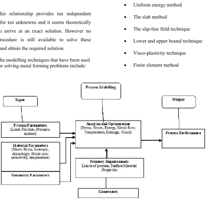
Figure 1: Process Design for Metal Forming
UNIFORM ENERGY METHOD
The uniform energy method or uniform plastic deformation methods, proposed by Siebel (1932), is especially useful for steady-state problems such as drawing and extrusion although it can be applied to non-steady-state problems. In this method the deformation mechanism of the system is simplified by assuming that plastic deformation occur only under principle stresses. The frictional effects are then superimposed on the system and are assumed will not affect the stress distribution. The general approach in this method in to equate the infinitesimal internal work and them to integrate this over the entire deformation region to evaluate the work done. The effect of non-homogeneous deformation is compensated by the use of appropriate correction factor.
SLAB METHOD
https://edupediapublications.org/journals/index.php/IJR/ equations for atypical slab is solved subject to the given
stress boundary conditions. The distribution of contact pressure at the tool-work interface is obtained by simplified the stress state. The method assumes that:
The stresses on the slab surface perpendicular to the flow direction are principle directions and they are uniformly distributed over this surface.
The internal stress distribution is not affected by the frictional forces.
The slab, straight and covered, of infinitesimal thickness is selected parallel to the plane perpendicular to the flow direction at any arbitrary point in the deformation zone. Static equilibrium of the slab gives the differential equation which is them converted to an equation which can be integrated. Integration subjected to the boundary conditions gives the required forces and other relevant information. Both slab and uniform energy method usually lead to average forming stresses.
SLIP-LINE FIELD METHOD
The slip-line field method introduce by Hencky (1923) is a technique for solving plastic flow problems by establishing the maximum shear-lines for slip line field. The slip-line fields, the direction of maximum shear at every point in the deformation material. Since shear is always accompanied by a complimentary shear equal magnitude and opposite sense, there will always be two mutually perpendicular directions of maximum shear stress at every point. The slip-line fields, consists of orthogonal network of shear lines in a plastic-flow field. These shear lines which have come to be known as slip lines, satisfy the static equilibrium conditions in the deformation material.
In the slip-line field method, the metal outside the plastic zone and the tools are assumed to be rigid. The rigid material upstream from the plastic zone
during steady-state forming changes to plastic state as it crosses the boundary slip line. Thus the slip-line field method, like the uniform energy method and the slab method, ignores the effects of elastically loaded material that surround the plastic zone.
This method is generally valid for plane strain deformation in which stresses and velocity can be assumed to lie in a plane and do not vary along the co-ordinates axis perpendicular to the plane. The stresses and velocities can be projected on a surface and all plane parallel to this surface have identical stress and velocity pattern. In the slip-line field method instead of deriving a solving, the solution is first proposed in the form of a slip-line field and then shown to be kinematically admissible and that it satisfies all boundary conditions. The solution proposed is not a unique one and other criteria may have to be considered to obtain the best possible solution.
UPPER BOUND METHOD
Available online: https://edupediapublications.org/journals/index.php/IJR/ P a g e | 51 An upper bound solution is required to satisfy
only the kinematic conditions in terms of strain increments on the associated strain rates in a plastically deformation medium and does not necessarily satisfy the stress equilibrium equations. An important concept involved is that of a kinematically admissible velocity field i.e. the velocity field must satisfy the constraints of volume constancy and velocity boundary conditions. A kinematically admissible velocity field may have discontinuities in the tangential component along certain surface, but the normal component must be caving formation or pile up of material in a uniformly deforming body. The unknown parameters in the kinematically admissible velocity field are determined using the upper bound theorem. Like in slip-line field methods, in this method also the solution proposed is not a unique one and the least value of the upper bound is the best value.
VISIOPLASTICITY METHOD
The visioplasticity method which combines experiments and analyses was suggested by Thomsen et al. (1954). After the velocity vectors have been determined from the actual test, the strain rates are calculated and the stress distributions are obtaining reliable solutions for processes in which experimental determination of the velocity vectors was possible. The limitation of this method lies in the errors involved in the measurement of velocity vectors and the inevitable successive differentiation of the measured velocity field.
The velocity vector field can be established by placing the grid pattern on the meridian plane on a cylindrical workpiece or on a plane perpendicular to the direction of metal flow and deriving the distortion rate. A simple way of evaluating this is by photographing the grid pattern after each incremental forming step and observing the particle movement through new positions of grid lines intersections. A few incremental steps are usually sufficient to obtain the flow pattern in steady-state deformation. In non-steady
deformation processes only one forming step can be used. After establishing the instantaneous particle flow field the grid pattern can be analysed to determine the stress, strain and strain- rate patterns.
FINITE ELEMENT METHODS
Slip-line and upper-bound methods are useful for making predictions for forming loads overall geometry changes in the deformation workpiece, qualitative modes of metal flow an optimal process conditions. Accurate determination of the effects various process parameters on metal flows become possible only after the finite element method was used for analysing metal forming processes. In the finite element method the domain of interest is divided into a number of suitable elements and the governing differential equations of the system are reduced to algebraic equations by using appropriate approximation for the field variable over the elements.
In the analysis of metal forming the plastic strains usually out-weigh the elastic strains and idealisation of rigid- plastic or rigid visco-plastic material behaviours are acceptable. The resulting analysis based on this assumption is known as the flow formulation. In some application, phenomena associated with elasticity cannot be neglected. In these types of formulations i.e. solid formulation, the material is considered to behave as an elastic-plastic or elastic visco-plastic material. Almost all metal forming processes have been analysed by finite element method due to its ability to handle a wide class of boundary values problems without restriction on workpiece geometry. This can be achieved by selecting a proper mesh.
MESHFREE METHOD
https://edupediapublications.org/journals/index.php/IJR/ investigated with accuracy. Gauss Integrations is
commonly used in Galerkin based meshfree methods. Although the growing body of research in meshfree methods demonstrates the effectiveness of these methods to solve large deformation and complex contact conditions, the high CPU cost of the GalerkinbasedMeshfreeis still problematic.
CONCLUSIONS
There is uniform energy method suited for steady-state problem and the main disadvantage is that it yields only an average value of the load. The slab method discussed usually provides better solution when variable such as external friction can be included, both these gives satisfactory result when shear deformation is relatively small.
The slip-line field method, the uniform energy method and the slab method, ignores the effects of elastically loaded material that surround the plastic zone. The slip line field method is applicable for plane-strain problems only. The upper bounded method is flexible technique based on assumption that flow field which satisfies the continuity equation and velocity boundary conditions without imposing the requirement of stress equilibrium. Also for plane-strain problems it is now being used for axisymmetric and three-dimensional problems.
The Visio-plasticity method involves experiments and analysis. The velocity vectors and hence the strain rates that are evaluated from the deformed grid pattern are obtained experimentally. The main disadvantage of the method is that flow pattern must be obtained experimentally before any predictions can be made. The limitation of this method is the error which is likely to be involved in the measurements of distorted grid points and the inevitable successive differentiation of the measured velocity field. The method is useful for the study of metal forming processes and for comparing the results obtained using other methods since the visio-plasticity method
provides exact solution in engineering sense.
The most significant development in the modelling of metal forming processes in recent years has been the application of FEM. The major advantage of this method is its applicability to a wide range of boundary value problems with little restrictions on the geometry of workpiece. The method is capable of prediction instantaneous values of velocity, strain, strain rate, stresses and temperature at any section in the deformation material. In the FEM technique, the material can be assumed to be rigid-plastic or rigid visio-plastic. This not only reduces the computational time for simulation flow of material but also predicts values of velocities, strain rates, strain, stresses and temperature with sufficient accuracy for most practical purposes. Meshfree method is in developing stage in metal forming process and continuous research for developing the Meshfree methods in application of metal forming process.
REFERENCES
[1]Kobayashi S., Oh S., and Altan, T, “Metal Forming and the Finite Element Method”, Oxford University Press, 1989.
[2]Sachs G., “SpanloseFormung der Metalle”, Springer-Verlag, Berline, 1931.
[3]Siebel E., “Die FormgebungimBildsamenZustande”, VerlagStahleisen, Dusseldorf, 1932.
[4]Drucker D. C., “Introduction to Mechanics of Deformable Solids”, McGraw-Hill, New York, 1967.
[5]Drucker D. C., Greenberg H.J., and Prager W., “Extended Limit Analysis for continuous Media”, Trans. ASME, J.Appl. Mech., Vol.73,pp-371. 1951.
Available online: https://edupediapublications.org/journals/index.php/IJR/ P a g e | 53 [7]Thomsen E.G., Yang C. T., and Bierbower J.B., “An
Experimental investigation of the Mechanics of Plastic Deformation of Metal ”, University of California Press, Berkeley, p-89,1954.
[8]Duggirala R., “Using of Finite Element Method in Metal Forming Processes”, Journal of metal forming, Vol. 42(2), pp- 24-27, 1990.
[9]C. A. M. Duarte and J. T. Oden, “A h-p Adaptive Method Using Clouds”, Comput. Meth. Appl. Mech. Engng. 139 (1996) 237-262.
[10] I. Babuska and J. M. Melenk, “The Partition of Unity Method”, Int. J. Numer. Meth. Eng. 40,(1997) 727-758.
[11] T. Belytschko, Y. Y. Lu and L. Gu, “Element-Free Galerkin Methods”, Int. J. Numer. Meth. Eng. 37 (1994) 229- 256.
[12] Liu W. K., Jun S., and Zhang Y. F., “Reproducing Kernel Particle Methods”, Int. J. Numer. Meth.Fluids. 20 (1995) 1081-1106.
[13] Wu W.T., Jinn J.T., and Fischer C.E., Scientific Forming Technologies Corp, “Modeling Techniques in Forming Processes”, Handbook of Workability and Process Design, 2003 ASM International.
[14] Leo Gusel, Rebeka Rudolf, “Different Techniques For Strain Analysis In Metal Forming Processes” Industrial Engineering 24-26 April 2008, Tallinn, Estonia,pp-330-341.
[15] Gusel L., Anžel I., Brezočnik M. “Effect of lubrication on the stress distribution in an extruded material”, International Journal of Advanced Manufacturing Technology, Vol 25 (2005), pp. 288 – 291.