DOI : https://doi.org/10.32628/CSEIT195169
Elimination of Impulse Noise using Mean Median filter for Image
Enhancement
Trupti Arun Jangale, Raj Kumar Paul
Department of Computer Science & Engineering, Vedica Institute of Technology, Bhopal, Madhya Pradesh, India
ABSTRACT
In this method, we've got introduced a new technique for the improvement of gray scale images, when images are corrupted by salt and pepper noise that's additionally referred to as an impulse noise. Our suggested phenomena show a better output for Medium density impulse noise as compare to the opposite renowned filters like standard Median Filter (SMF), a decision based mostly Median Filter (DBMF) and modified decision based Median Filter (MDBMF), Nonlinear filter (NLF) and so on. Our projected technique worked on two steps, within the beginning is that the detection of noisy pixels and within the second step is that the removal of noisy pixels. For detection of noisy constituent apply condition pixels values lies in between 0 to 255 it noisy it's noisy free pixels. In our second step that's the removal of noisy pixel recommended technique that's replaces the noisy pixel by alpha trimmed mean median value. Different grayscale pictures are tested via proposed technique. The experimental result shows higher Peak Signal to Noise ratio (PSNR) values and with higher visual and human perception.
Keywords : Gray Scale, Impulse Noise, Trimmed Mean, Median, Unsymmetricness
I. INTRODUCTION
Digital images play a very important role each in existence applications like satellite television, resonance imaging, laptop pictorial representation also as in areas of analysis and technology like geographical data systems and physical science. Knowledge sets collected by image sensors are typically contaminated by noise. Imperfect instruments, issues with the information acquisition method, and intrusive with natural phenomena will all degrade the information of interest. what is more, noise are often introduced by transmission errors and compression. Thus, de-noising is usually a necessary and also the start to be taken before the image knowledge is analyzed. it's necessary to use associate
degree economical de-noising technique to catch up on such knowledge corruption.
Image De-noising: -
the noise removal aims at rising the image quality for visual examination.
The de-noising technique aims to attenuate noise through 2 phases particularly,
1. Noise detection 2. Noise removal
Classification of De-noising Algorithm: -
As shown in Figure 2.2 below, there are two basic approaches to image denoising, spatial filtering methods and transform domain filtering methods.
• Spatial Filtering
• Non-Linear Filters
• Linear Filters
• Linear and nonlinear Filtering Approach
• Median Filter (M.F.)
• Mean Filter (M.F.)
• LMS adaptative Filter
• Center Weighted Median Filter (CWM)
• Adaptative Mean Filters (AMF)
• Progressive shift Median (PSM)
• Switching Median Filter (SMF)
• Adaptative Weighted Median Filtering
• Adaptative Median Filter (AMF)
• Dision based Unsymmetrical Trimmed Mean Filter (DBUTMF)
• Modofied Dision primarily based Unsymmetrical cut Mean Filter (MDBUTMF)
Idea of noise:-
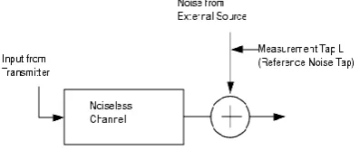
An image passes through many media and transmission channels before it reaches the process part. throughout this point, the image is also subject to interference from many sources.
Figure 1 (a) : Introduction of noise into the system
Figure 1 (b): Introduction of noise into the clean signal
These embrace photographic grain noise, electrical device noise, and transmission errors. Any globe device is suffering from a particular degree of noise, whether or not it's thermal, electrical or otherwise. Additive noise, in all probability the foremost common kind, may be expressed as:
I (t) = S (t) + N (t) Where
I (t) = ensuing knowledge measured at time t, S (t) = original signal measured, and
N (t) = noise introduced by the atmosphere and different sources of interference.
kinds of noise
The types of Noise are following:-
I. Electronic equipment noise (Gaussian noise) II. Impulse noise (Salt-and-pepper noise) III.Shot noise (Poisson noise)
IV.Speckle noise V.Brownian Noise
Image noise removal victimization Filters:- Filtering whereas not Detection:-
centre part is that the constituent of interest. once the mask is affected starting from the left-top corner of theimagetothe right-bottom corner, it performs some mathematics operations whereas not discriminating any constituent.
Detection followed by Filtering:-
This type of filtering involves two steps. In commencement it identifies screeching pixels and in second step it filters those pixels. Here in addition a mask is affected across the image and a number of mathematics operations unit of measurement distributed to look at the screeching pixels. Then filtering operation is performed exclusively on those pixels that unit of measurement found to be screeching inside the previous step, keeping the non-noisy intact.
Mean filter:-
Mean filtering may be a easy, intuitive and simple to implement technique of smoothing images, i.e. reducing the quantity of intensity variation between one pel and also the next. It's usually accustomed cut back noise in images. The thought of mean filtering is just to interchange every pel price in a picture with the mean (`average') price of its neighbours, as well as itself. This has the impact of eliminating pel values that square measure atypical of their surroundings. Thearithmeticmean filter may be a terribly easy one and is calculated as follows: Replace every pel by the typical of pels during a sq. window close this pixel
Median filter:-
The median filter is often accustomed scale back noise in a picture, somewhat just like the mean filter. However, it usually will a much better job than the slides, entry by entry, over the whole signal. For 1D
signal, the foremost obvious window is simply the primary few preceding and following entries, whereas for 2nd (or higher-dimensional) signals like images, additional complicated window patterns are potential (such as "box" or "cross" patterns). Note that if the window has associate degree odd range of entries, then the median is easy to define: It's simply the center price on balance the entries within the window are sorted numerically. For an excellent range of entries, there's quite one potential median.
1-D median Filter:-In 1D median filter, we have a tendency to take into account the filtering window slippy over a 1D array (either horizontal or vertical) of pixels. Assume the 5 pixels presently within the windows are:
Where the center picture element with price two hundred is associate isolated picture element and it's out-of-range (noise). The median of those 5 values is found by sorting the values (in either ascending or falling order). the center price is that the median:
The original picture element price two hundred is replaced by the median a hundred and ten.
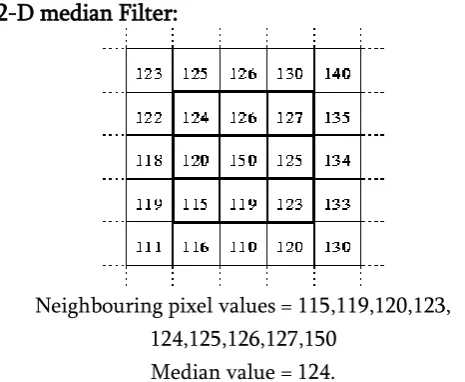
2-D median Filter:
Neighbouring pixel values = 115,119,120,123, 124,125,126,127,150
Median value = 124.
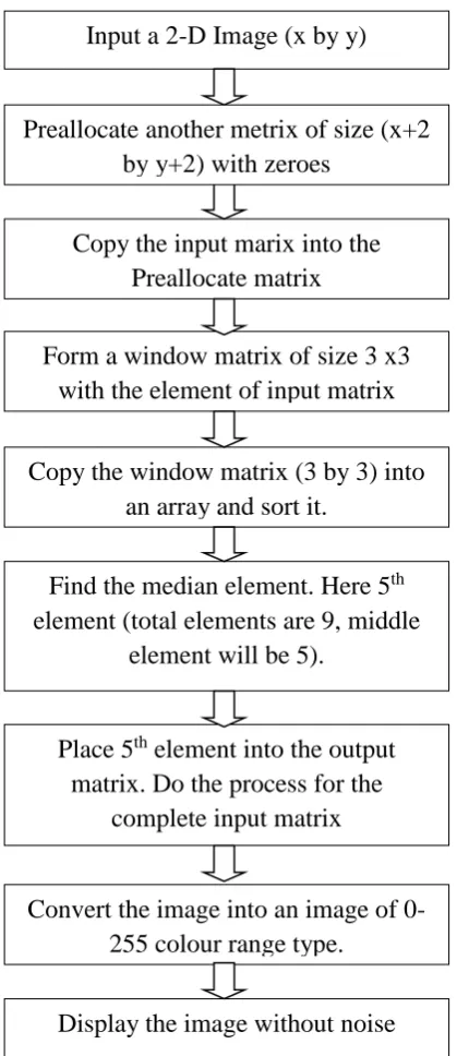
Figure 2 : Flow chart o 2-D Median Filter
Another concern within the application of the median filter is that the form of the neighbourhood mask. A square-shaped mask will erode the corners of rectangular objects, whereas a cross-shaped neighbourhood mask can leave corners intact.
II. PROPOSED METHOD
We have develop the trouble-free algorithm in which we execute the noise finding and noise removal
process simultaneously. In the suggested method employ the smallest window dimension which conserve the very well information of image.We divide these pixels into matrix form and called it window. Then we analyse every pixel by sliding that window over the entire image. The window of size 3x3 choose for noise recognition and noise elimination. The windowpane contains total 9 elements which are as follows:
Z1, Z2, Z3, Z4, Z5, Z6, Z7, Z8, Z9.
Table 1 Filtering window of size 3x3 Column 1 Column 2 Column 3
Row 1 Z1 Z2 Z3
Row 1 Z4 Z5 Z6
Row 3 Z7 Z8 Z9
Different blocks are shown for different steps. At the starting there is filtering window of size 3x3 has been selected and calculated gray value of pixels according to the strength of intensity of every pixel.
ALGORITHM
Step-1:-
In the first step select a image for image processing than apply pre-processing task in this image byusing pre-defined command in MATLAB. The prepressing task are first convert our target image into a gray scale level. Second convert image into a strand image that is 255X255. Now selected image is prepared for dealing out. For the pre doling out assignment and all other things are implemented in MATLAB. In matrix lab. A large no. function file available for the performing the initial task in the digital image processing. Also done the padding of zeros and ones in image.
Select a target image - [x] = imread(‘Test image.jpeg’)/ for the read of image
Input a 2-D Image (x by y)
Copy the input marix into the
Preallocate matrix
Form a window matrix of size 3 x3
with the element of input matrix
Copy the window matrix (3 by 3) into
an array and sort it.
Find the median element. Here 5
thelement (total elements are 9, middle
element will be 5).
Place 5
thelement into the output
matrix. Do the process for the
complete input matrix
Convert the image into an image of
0-255 colour range type.
Display the image without noise
Preallocate another metrix of size (x+2
Step-2:-
In the second step apply impulse noise or can say salt and pepper noise in this image with the help Matrix laboratory function. In this step apply noise with the help of add-noise function in on the image.
[y] =imnoise(x,’Salt and Pepper’, Present of noise)
Step-3:-
In the third step for the preservation of corner, in this step preserve the corner we the help of zeros and ones padding in the boundary side of the image. This is use for the protection of corner of the digital image pixels.
Step-4:-
Noise elimination stage. In this stage first we divide a whole image into a small 3X3 window. Now relate the trimming situation. This condition isknown asnoise identification stage. In this stage check the pixel values.In which pixels are stuck between 0 to 255 ranges or not. Here two cases are generating.
If
X(ij) = 0<Y(ij)<255 / condition true Pixels Noise Free
else
X(ij) ≠ 0<Y(ij)<255 / condition Pixels are Noise End
Where X(ij) is the image small 3x3 windows pixels values.And Y(i,j) is the center pixel of targeted pixel of the small 3X3 window.
Table 2 3x3 windows pixels value
Column 1 Column 2 Column 3
Row 1 Z1 Z2 Z3
Row 1 Z4 Z5 Z6
Row 3 Z7 Z8 Z9
Condition 1- If Pixels are between (0) Zero and two five five (255) then they are noise free and shift to reinstatement digital image pixels.
Condition 2- digital images pixel values are not between in the range then they are moved to step 3.
Step 3: In the step third check the window. Here two cases are arise
1. In a small 3X3 window contain all elements are zeros (0’s) and two fifty five (255’s). In this condition apply mean filter. Take a mean of all pixel in the small 3x3 windows all element aspect centerpixel , and replace this value mean value by the targeted pixel. condition apply median filter for this case. Take a median of all zeros and two fifty five and replace this value by centre pixel value.
Mean Filtering (MUTMMF), will next part of this report. Shows the result and simulation.
III. RESULT strongly sufficient with perceptual excellence. It should be use therefore, with other quality check good resultant image and poorer for a reduced quality image. It calculate image reliability, that is, nearer the transformed image resembles the original image.In this proposed work on the source of our image dimension 255×255, we mentioned peak signal to noise ration and mean square error are as follows:
The PSNR is expressed as:
𝑃𝑆𝑁𝑅 = 10 𝑙𝑜𝑔10
Graphic User Interface (GUI) in MATLAB:-
In this preceding section, the image Tool GUI and preservation of the images in this research, in a user-friendly environment. First of all, the images are selected by clicking the browse and Select Images. A browser will appear afterwards to allow the user to select the images, which can be any of the following file formats:
Layout implementation of image enhancement based fusion techniques is done by following steps.
▪ First create simple Graphical User Interface (GUI) window.
▪ Second add impulse noise with the help of imnoise command in this GUI.
▪ Third step apply our proposed method that is removal of noise.
▪ Fourth stepcalculated the image enhancement parameters like peak signal to noise ratio, mean square error, mean absolute error.
Fig. 3 – Shows the GUI of Proposed Method
TABLE4CALCULATEDPSNROFPROPOSED ALGORITHMFORLENAIMAGE
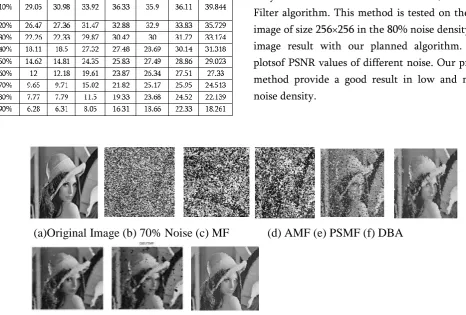
Graphical representation of result of our proposed method is shown in the blow the graph. Here in this plot we have compare with different algorithms they are - median filter,adaptive median filter, decision based algorithms, modified decision based unsymmetric trimmed median filter, Non-linear Filter algorithm. This method is tested on the ‘Lena’ image of standard sizeshown plotsof PSNR values of different noise. Our proposed method provide a good result in low and medium noise density. Here compression with different filters against noise densities for Lena image is shown in Figure .
In the figure 5 put side by side our proposed method visual results compare with different algorithms they are - median filter,adaptive median filter, decision based algorithms, modified decision based unsymmetric trimmed median filter, Non-linear Filter algorithm. This method is tested on the ‘Lena’ image of size 256×256 in the 80% noise density ‘Lena’ image result with our planned algorithm. Shown plotsof PSNR values of different noise. Our proposed method provide a good result in low and medium noise density.
Figure 4: Proposed outcome for ‘Lena’ test image
(a)Original Image (b) 70% Noise (c) MF
(d) AMF (e) PSMF (f) DBA
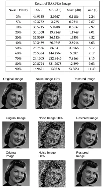
Table 5 Different values of Barbra image Result of BARBRA Image
Noise Density PSNR MSE(dB) MAE (dB) Time (s)
3% 44.9155 2.0967 0.1486 2.24
5% 42.3732 3.765 0.2541 2.67
10% 38.5745 9.0288 0.5632 2.97
20% 35.1368 19.9249 1.1749 4.01
30% 32.5039 36.5334 1.9553 4.82
40% 30.3439 60.0745 2.8946 6.03
50% 28.7536 86.641 3.9566 6.17
60% 26.5334 144.4569 5.582 7.17
70% 24.1005 252.9446 7.8463 8.15
80% 20.8724 531.9078 12.599 9.63
90% 16.9621 1308.8 23.8651 11.49
Figure-6 Shows the outcome of proposed method for ‘girl’ image
Original Image Noise Image 10% Restored Image
Original Image Noise Image 20% Restored Image
Original Image
Noise Image 30%
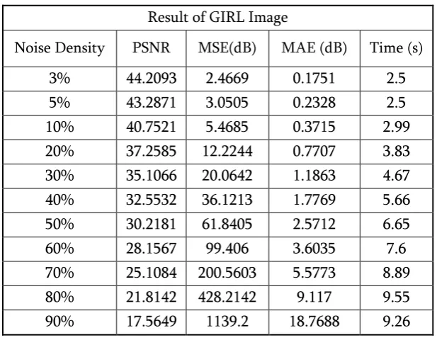
Table 6 different values of Girl image
Result of GIRL Image
Noise Density PSNR MSE(dB) MAE (dB) Time (s)
3% 44.2093 2.4669 0.1751 2.5
5% 43.2871 3.0505 0.2328 2.5
10% 40.7521 5.4685 0.3715 2.99
20% 37.2585 12.2244 0.7707 3.83
30% 35.1066 20.0642 1.1863 4.67
40% 32.5532 36.1213 1.7769 5.66
50% 30.2181 61.8405 2.5712 6.65
60% 28.1567 99.406 3.6035 7.6
70% 25.1084 200.5603 5.5773 8.89
80% 21.8142 428.2142 9.117 9.55
90% 17.5649 1139.2 18.7688 9.26
IV. CONCLUSION
The new proposed algorithm has been introduced to manage the problems, namely, poor image enhancement or we can say enhancement at high noise density that is frequently enhanced in the mean absolute error (MAE), mean square error (MSE) and peak signal to noise ratio. In this proposed workModified unsymmetric trimmed median Mean Filtering (MUTMMF) is used for enhancing both the peak signal to noise ratio. The performances of proposed Modified unsymmetric trimmed median Mean Filtering (MUTMMF) are quantitatively vies as well as the individual perception show better outcome as compare last decade algorithms. Results reveal that the proposed filter exhibits improved performance in comparison by means of Median Filter (MF) [5], Adaptive Median Filter (AMF) [7], Progressive Switching Median Filter (PSMF) [11],Decision Based Algorithms (DBA) [16], Modified Decision Based Algorithms (MDBA), Modified Decision Based Unsymmetric Trimmed Median Filter [29], Modified Non-Linear Filter Algorithm (MNF)in terms of improved MAE,
MSE and PSNR. Indifference to mean filter and further accessible algorithms, the new algorithm exploits a tiny 3x3 window containing only eight neighbors of the corrupted pixel that have advanced bond this provides a good edge protection , also better edge protection as well as more better person and illustration prescription. The proposed filter demonstrates trustworthy and conventional performance among various range of noise densities increasing from 10%-90%. The performance of the introduced methodology has been tested at low and medium densities on different level. In case of high noise density levels the new proposed algorithm gives better presentation as evaluate with other presented noise removal algorithms.
V. REFERENCES
[2] Fundamentals of Digital Image Processing, S. Annadurai, R. Shammugalakshmi, Pearson Education India.
[3] Castleman Kenneth R, Digital Image Processing, Prentice Hall, NewJersey, 1979 [4] T.A. Nodes and N.C. Gallagher, Jr., “The
output distribution of median type filters,” IEEE Trans. Communication., 32(5): 532-541, 1984.
[5] A.K.Jain,Fundamentals of digital image processing. Prentice-Hall, 1989.
[6] David L. Donoho and Iain M. Johnstone., “Adapting to unknown smoothness via wavelet shrinkage”, Journal of the American Statistical Association, vol.90, no432, pp.1200-1224, December 1995. National Laboratory, July 27, 2001.
[7] H. Hwang and R. A. Hadded, “Adaptive median filter: New algorithms and results,” IEEE Trans. Image Process., vol. 4, no. 4, pp. 499–502, Apr. 1995.
[8] E. Abreu and S.K. Mztra,” A Signal-Dependent Rank Ordered Mean (Sd-Rom) Filter –ANew Approach For Removal Of Impulses From Highly Corrupted Images”, 0-7803-2431- 5/95$ 4.000 1995 IEEE.
[9] R. Yang, L. Yin, M. Gabbouj, J. Astola, and Y. Neuvo, “Optimal weighted median filters understructural constraints,” IEEE Trans. Signal Processing vol. 43, pp. 591–604, Mar. 1995.
[10] Scott E Umbaugh, Computer Vision and Image Processing, Prentice HallPTR, New Jersey, 1998.
[11] Zhou Wang and David Zhang, “Progressive Switching Median Filter for the Removal of Impulse Noise from Highly Corrupted Images", IEEE Transactions On Circuits And Systems—Ii: Analog And Digital Signal Processing, Vol. 46, No. 1, January 1999.
[12] A. Ben Hamza, P. Luque, J. Martinez, and R. Roman, “Removing noise and preserving details with relaxed median filters,” J. Math. Imag. Vision, vol. 11, no. 2, pp. 161–177, Oct. 1999.
[13] V. Strela. “Denoising via block Wiener filtering in wavelet domain”. In 3rd European Congress of Mathematics, Barcelona, July 2000. BirkhäuserVerlag.
[14] S. Zhang and M. A. Karim, “A new impulse detector for switching median filters,” IEEE Signal Process. Lett., vol. 9, no. 11, pp. 360– 363, Nov. 2002.
[15] T. Yahagi. "A Random-valued Impulse NoiseDetector Using Level Detection", 2005 IEEEInternational Symposium on Circuits and Systems, 2005.
[16] K. S. Srinivasan. "A New Fast and Efficient Decision-Based Algorithm for Removal of High-Density Impulse Noises", IEEE Signal Processing Letters, 3/2007
[17] JafarRamadhan Mohammed. "An Improved MedianFilter Based on Efficient Noise Detection for HighQuality Image Restoration", 2008 Second Asia InternationalConference on Modelling & Simulation (AMS).
[18] V.R. Vijaykumar. "Detail preserving median basedfilter for impulse noise removal in digital images",2008 9th International Conference on Signal Processing.
[19] S. Saudia. "Salt & pepper impulse detection andmedian based regularization using Adaptive Median Filter", TENCON 2008 - 2008 IEEE Region 10 Conference, 11/2008 [20] DENG Xiuqin, XIONG Yong PENG Hong , A
[21] Ashraf Aboshosha. "Image denoising based on spatialfilters, an analytical study", 2009 InternationalConference on Computer Engineering & Systems, 12/2009.
[22] V.R.Vijaykumar, P.T.Vanathi,
P.Kanagasabapathy and D.Ebenezer, “Robust Statistics Based Algorithm to Remove Salt and Pepper Noise in Images”, International Journal of Information and Communication Engineering 5:3 2009.
Cite this article as :