IJEDR1504037
International Journal of Engineering Development and Research (www.ijedr.org)255
A Review on Experimental Investigation of U-Tube
Heat Exchanger using Plain Tube and Corrugated
Tube
1
Dhavalkumar A. Maheshwari,
2Kartik M. Trivedi
1ME Student, 2Assistant Professor 1Mechanical Engineering Department,
1L. J. Institute of Engineering and Technology, Ahmedabad, India
________________________________________________________________________________________________________
Abstract - An objective of the present dissertation work is to design and develop a PROTOTYPE model of U-Tube type counter flow Heat exchanger. A PROTOTYPE model of U-Tube heat exchanger is created using Tubular Exchange Manufactures Associations (TEMA) standards. The Dissertation is about preparing the PROTOTYPE model as well modifying an experimental setup U-tube heat exchanger and use of different type of tubes configuration like using plain tube and corrugated tube for the different type of parameter efficiency, effectiveness pressure drop, heat transfer rate, overall heat transfer coefficient etc. for in order to reduce pressure drop and increase heat transfer rate, efficiency and heat transfer area. Using Logarithmic mean temperature difference (LMTD) method numerical result are compared with experimental result.
Index Terms - heat transfer rate, U-tube heat exchanger, corrugated tube, flow arrangement, TEMA standards.
________________________________________________________________________________________________________
I.INTRODUCTION
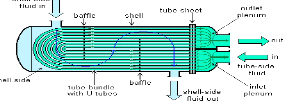
In oil-refinery industries, U- Tube heat exchanger are commonly used which have a shell (a large pressure vessel) with a bundle of u shaped tubes inside the shell to transfer of heat between two fluid stream that are kept at different temperatures. Heat exchangers are commonly classified according to type of constructions and flow arrangement (Incropera and DeWitt, 2002). Here, the discussion is restricted one of common type of shell and tube type heat exchanger which classified as per type of constructions of heat exchanger- a u-tube type heat exchanger (UTHX). U tube heat exchanger consists of a shell and u tubes as well as baffles, tube sheet. The arrangement of tube and shell is shown in figure 1. One of the fluid flows through shell and other one flows through tubes. In shell side fluid is cold fluid and tube side fluid is hot fluid and flow arrangement of fluid in UTHX is counter flow type. In counter flow arrangement flow direction of hot fluid and cold fluid are completely opposite to each other and this flow arrangement are most efficient in heat exchanger because they allow the highest log mean temperature difference between hot and cold stream. U-Tube heat exchangers are most common of the various types of unfired heat transfer equipment, which are used in the industrial field as a conventional & nuclear power plants, process industries, petroleum refining and steam generation. Although they are not compact, they are robust and their rugged shape makes them well suited for high pressure application. Moreover they are versatile and can be designed to suit for almost all application. Due to technological advancement and growth of industrial process as well as the environmental and Energy concerns, heat exchanger system must be improved to transfer heat more efficiently. The basic principle of operation of UTHX is very simple as flow of two fluids with different temperature brought into close contact but prevented from mixing by a physical barrier. The fluids can be either liquids or gases on either the shell or tube side. In this way, waste heat can be put to use. This is an efficient way to conserve energy. U-Tube heat exchanger are designed and fabricated according to the standards of the Tubular Exchanger Manufactures Association (TEMA).
Component of UTHX:
It is essential for the designer to have a good working knowledge of the mechanical features of UTHEs and how they influence thermal design. The principal components of an UTHE are:
1. Shell; 2. Shell cover; 3. U-Tubes; 4. Tube-bundle; 5. Baffles; 6. Tube sheet
IJEDR1504037
International Journal of Engineering Development and Research (www.ijedr.org)256
FIGURE 1: U TUBE HEAT EXCHANGERThe principle advantage of U-Tube heat exchanger (UTHX) is it’s less costly than floating head or packed floating head design heat exchanger. U-tube design allows for differential thermal expansion between the shell and tube bundle as well as for individual tubes. UTHX are capable of withstanding thermal shock applications. In UTHX, bundle can removed from one end for cleaning or replacement.
The disadvantage of UTHX design is that tubes have u shape so tubes can be cleaned by chemical means only. There is no single tube pass or true countercurrent flow is possible. Due to U-tube nesting, individual tube is difficult to replace and tube wall thickness at the U- bend is thinner that at straight portion of the tubes. Draining of tube circuit is difficult when mounted with the vertical position with the head side up.
The current project is focus on to reduce pressure drop at shell side and at u-tubes side as well as to increase heat transfer rate. This can be done in UTHX using plain tube and corrugated tube. In corrugated UTHX corrugated tubes are used instead of plain tube. Corrugated tube is produced by a plain tube with a spirally pattern. There are several advantages and disadvantages of using corrugated u-tube in UTHX.
To increase tube side heat transfer coefficients, with minimum increase in pressure loss.
Difficult to design or manufacture compared to plain tube.
Difficult to clean.
unpredictable characteristics
low running reliability
Design Consideration:
In design of heat exchangers, several factors that need to be considered are; 1. Corrosion should be avoided.
2. Resistance to heat transfer should be minimized. 3. The equipment should be sturdy.
4. Pumping cost should be kept low. 5. Space required should be kept low. 6. Required weight should be kept low.
7. Cost and material requirement should be kept low.
TEMA STANDARDS:
TEMA is a set of standards developed by leading heat exchanger manufactures that defines the design and manufacturing parameters of STHX. TEMA stands for Tubular Exchanger Manufactures Association. TEMA standards provide a recognized approach to end users and allow comparison between competitive designs for a given application. Different classes of TEMA standards are:-
TEMA R Covers Exchangers for the generally severe duties of the petroleum and related industries. TEMA B Covers Exchangers for moderate duties in commercial and general process application. TEMA C Covers Exchangers for use in chemical industries.
II.LITERATUREREVIEW
Vinous M. Hameed and Aliaa H. Akhbala [1] “Investigation of Heat Transfer on Smooth and Enhanced Tube in Heat
IJEDR1504037
International Journal of Engineering Development and Research (www.ijedr.org)257
effect on heat transfer augmentations. A more efficient rate is obtained at smallest pitch length. They derived a correlation for coagulated type aluminum tubes. The proposed correlation related the effect of pitch dimensions with required outlet temperature, it can calculate heat transfer coefficient and compared with other data. The proposed correlation can predict the experimental data with average relative error of 7% when compared with heat transfer coefficient. Another approach for calculating heat transfer coefficient was tried. The equation for calculating Nu is modified to suite the conditions for enhanced tubes type exchanger. The modified relation related to pitch dimensions data which gives very good agreement with average relative error of 17.23% when compared with experimental data. They also introduce helical baffles in shell side which gives more efficient heat transfer rates. The results shows that increment in heat transfer by using helical baffles over the smooth tube heat exchanger is is about 39% and 13% higher than without using helical bafflesLu Linping, Liang Ying [2] “Comparative Experimental Study On Performance of Corrugated Tube and Straight Tube Heat Exchanger” In this research paper the experiments on heat transfer coefficient, pressure drop and thermal stress were done with heat exchangers with corrugated tubes and straight tubes. By analyzing and comparing the heat transfer coefficient, pressure drop in tube and shell side, they concluded that the corrugated tube heat exchanger has better heat transfer coefficient, higher pressure drop and much lower stress caused by temperature difference. They concluded that the special channel of corrugated tube can enhance heat transfer largely; it makes this kind of heat exchanger suitable for the simulation of low Reynolds number. The pressure drop of corrugated tubes is bigger than straight tubes. Axial forces and stresses of corrugated tube is much less than straight tube.
J.J. Liu, Z.C. Liu, W. Liu [3] “3D numerical study on shell side heat transfer and flow characteristics of rod-baffle heat exchangers with spirally corrugated tubes” This article presents a numerical simulation of the shell side flow in rod-baffle heat exchangers with spirally corrugated tubes (RBHXsSCT). Results are compared with those in rod-baffle heat exchanger with
III.plain tubes (RBHX). Simulation is conducted to improve the thermo-hydraulic performance in longitudinal flow heat exchangers and to obtain an understanding of the physical behavior of thermal and fluid flow in the RBHXsSCT with Reynolds number ranging from 6000 to 18,000. Simulation results show that the Nusselt number in RBHXSCT with one-start spirally corrugated tubes can be 1.2 times that in RBHX when the Reynolds number is 18,000. The heat transfer quantities in the RBHXsSCT with one-start, two-start, three-start, and four-start spirally corrugated tubes are 104.6%, 105.4%, 106.7%, and 109.6%, respectively, higher than that in RBHX. The pressure drop in RBHX is 1.21, 1.16, 1.12, and 1.08 times that in RBHXsSCT with start, two-start, three-start, and four-start spirally corrugated tubes, respectively. The RBHXSCT with one-start spirally corrugated tubes can achieve an efficiency evaluate coefficient of 1.35.
Hamed Sadighi Dizaji, Samad Jafarmadar, Farokh Mobadersani [4] “Experimental studies on heat transfer and pressure
drop characteristics for new arrangements of corrugated tubes in a double pipe heat exchanger” Heat transfer, pressure
drop and effectiveness in a double pipe heat exchanger made of corrugated outer and inner tubes have been experimentally investigated in this paper. Both of the inner and outer tubes were corrugated by means of a special machine. New various arrangements of convex and concave corrugated tube were investigated. Heat transfer coefficient was determined using Wilson plots. Hot water (inner tube) and cold water (outer tube) inlet temperatures were maintained at around 40 ᵒC and 8 ᵒC respectively. Experiments were performed over the Reynolds number range of 3500-18,000, based on the hydraulic diameter of the annular space between the two tubes. Hot water Reynolds number was kept constant at around 5500. Findings indicated that the outer tube corrugations and arrangement type of corrugated tubes have significant effect on thermal and frictional characteristics. Maximum effectiveness was obtained for heat exchanger made of concave corrugated outer tube and convex corrugated inner tube.
Shiv Kumar Rathore, Ajeet Bergaley [5] “Comparative Analysis of Finned Tube and Bared Tube Type Shell and Tube Heat Exchanger” The objective of this paper is to identify the advantages of low-finned tube Heat Exchangers over Plain tube (Bare Tube) units. To use finned tubes to advantage in this application, several technical issues were to be addressed. (1) Shell side and tube side Pressure, (2) Cost, (3) Weight and (4) Size of Heat Exchanger, Enhanced tubular heat exchangers results in a much more compact design than conventional plain tube units, obtaining not only thermal, mechanical and economic advantages for the heat exchanger, but also for the associated support structure, piping and skid package unit, and also notably reduce cost for shipping and installation of all these components. A more realistic comparison is made on the basis of respective cost per meter of tubing divided by the overall heat transfer coefficient for the optimized units, which gives a cost to performance ratio. The results of this analysis shows that the finned tube heat exchanger is more economical than Conventional Bare tube Exchanger, The tube side pressure drop and fluid velocity is higher than the conventional bare tube exchanger, which prevent fouling inside the tubes, The shell side pressure drop is some lesser but fluid velocity is higher than the conventional heat exchanger. The shell diameter of finned tube Exchanger is lesser than Conventional bare tube heat exchanger, which saves sheet material and reduces the size of the shell, which helps to easily installation in the plant.
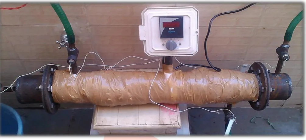
Darshan Patel, Prexa Parikh [6] “Numerical Simulation and Experiment Performance for Comparison of Shell and Tube
IJEDR1504037
International Journal of Engineering Development and Research (www.ijedr.org)258
Pressure Drop at shell side, Large Pressure Drop at tube side, Less Heat Transfer rate and Cost is very high and also done analysis of corrugated tube and compare with existing plain tube. They also make prototype experiment model of shell and tube heat exchanger in which plain and corrugated tube is use one after one and take reading for thermal analysis calculation and then compare Experiment Result to CFD. They concluded that CFD analysis results shows that increasing in temperature difference, increase in heat transfer rate and increasing in pressure drop by using corrugated tube instead of straight tubes in STHX.FIGURE 2: MODEL OF SHELL AND TUBE HEAT EXCHANGER
Kirtan Gohel [7] "Effectiveness improvement of shell and tube heat exchanger" They finish to infer that after performing experiment result of simple and helical baffle are compared. So it is also concluded that effectiveness of helical baffle is high compared to simple baffle for same inlet temperature of hot water and cold water
FIGURE 3: MODEL OF SHTX
III
CONCLUSIONFrom literature review it could be concluded that, entire U-Tube heat exchanger design by TEMA standards, LMTD method also include, we get clear idea about each and every parts design and we easily compare with standard data. After studying various configuration of Heat Exchanger using plain tubes and corrugated tubes it could be found that
A.Heat transfer rate and heat transfer coefficient of corrugated tube heat exchanger is higher than straight tube heat exchanger. B.In corrugated tube heat exchanger pressure drop is higher than straight tube heat exchanger.
REFERENCES
[1] Vinous M. Hameed† and Aliaa H. Akhbala “Investigation of Heat Transfer on Smooth and Enhanced Tube in Heat Exchanger “ International Journal of Current Engineering and Technology, Vol.5, No.3 2092 (June 2015) E-ISSN 2277 – 4106, P-ISSN 2347 – 5161.
[2] Lu Linping, Liang Ying“Comparative Experimental Study On Performance of Corrugated Tube and Straight Tube Heat Exchanger” Advanced Materials Research Vols 560-561(2012).
[3] J.J. Liu, Z.C. Liu, W. Liu“3D numerical study on shell side heat transfer and flow characteristics of rod-baffle heat exchangers with spirally corrugated tubes” International Journal of Thermal Sciences 89 (2015) 34-42, ISSN 1290-0729. [4] Hamed Sadighi Dizaji*, Samad Jafarmadar,“Experimental studies on heat transfer and pressure drop characteristics for new
IJEDR1504037
International Journal of Engineering Development and Research (www.ijedr.org)259
[5] Shiv Kumar Rathore, Ajeet Bergaley “Comparative Analysis of Finned Tube and Bared Tube Type Shell and Tube HeatExchanger “IJEIT/2012, volume 2, issue 1, July 2012 ISSN 2277-3754.
[6] Darshan Patel, Prexa Parikh “Numerical Simulation and Experiment Performance for Comparison of Shell and Tube Heat Exchanger with Plain Tube and Corrugated Tube” vol.2 Issue 5, May 2015, ISSN 2348-7968.