Thermal Efficiency of a Concentrating Solar Collector
Under High-Vacuum
Davide DE MAIO1,2, Carmine D’ALESSANDRO1,2, Daniela DE LUCA2,3, Marilena MUSTO1, Emiliano DI GENNARO3, Giuseppe ROTONDO1 and Roberto RUSSO2
1.Industrial Engineering Department, University of Napoli “Federico II”, Napoli, Italy
2 Institute for Microelectronic and Microsystem, National Research Council of Italy,
Napoli Unit, Italy
3 Physics Department, University of Napoli “Federico II”, Napoli, Italy
Correspondence: carmine.dalessandro@na.imm.cnr.it
Abstract: A new frontier in solar thermal panel technology can be a high vacuum collector, thick enough to be equipped with solar concentrators based on non-imaging optics, such as the Compound Parabolic Concentrators (CPC). The high vacuum technology guarantees higher operating temperatures thanks to the enhanced thermal insulation, which leads to pay particular attention to the absorber radiative emission. In this paper by means of numerical simulations we compare the efficiency of a flat selective solar absorber under high vacuum to the efficiency of a CPC under high-vacuum collector.
Keywords: solar energy; Compound Parabolic Concentrators (CPC); high vacuum insulated solar collectors
1. Introduction
Solar energy is one of the best candidates to produce process heat at mid temperatures to satisfy the industrial demand. The interest in improving solar thermal collector efficiencies is huge, in order to take full advantage from this source of energy. TVPSolar is a leading company in the field of high-performance solar energy conversion that develops and produces an innovative flat-plate solar thermal collector under high vacuum. Vacuum technology ensures that both gas convective and conductive losses are reduced to a negligible level, so that these flat-panels are able to reach high working temperatures (up to 200 °C) [1]. Concentrating Solar Power technology (CSP), combined with high vacuum insulation, could be an alternative to reach higher working temperatures. The sunlight concentration technology splits into two different broad categories: imaging and non-imaging concentration. As regarding Solar Thermal (ST) and photovoltaic (PV) applications, non-imaging concentration has been an interesting option, since mid-1960s [2]. CSP usually uses only direct-beam sunlight [3], so mirrors require high cleaning standards and tracking systems to efficiently harness solar energy in day-light hours, resulting in high maintenance costs and installation issues. Compound Parabolic Concentrator (CPC) is an example of non-imaging concentration of sunlight that could be designed for stationary or passive tracking thus having acceptable concentration ratio. Moreover, it can collect both direct-beam sunlight and part of diffuse light (only rays within the acceptance angle) [2] and concentrate them on an absorber tube. A new frontier in high efficiency solar collection could be a high vacuum flat solar panel, thick enough to be equipped with CPC. The CPC installed in a high vacuum envelope leads to various advantages: no need for mirror cleaning, no corrosion due to atmospheric agents, better insulation resulting in thermal loss reduction, possibility to deposit a IR reflective coating on the interior side of the glass to benefit from ‘photon recycling’ mechanism [4]. A pioneering work [5] has experimentally investigated the idea to place a CPC under vacuum to reach the high temperatures needed for methanol reforming but CPC dimensions and performances were limited by the small volume of the cylindrical vacuum chamber. To extend CPC sizes the vacuum chamber must increase too, so the surface under vacuum needs a mechanical support to sustain the glass against the atmospheric pressure and the CPC has to be designed to respect the support mechanical constraint.
The present work shows the impact on the thermal efficiency obtained by replacing the flat absorber with a CPC. The absorber tube surface is supposed to be coated with a solar selective coating having the same optical properties of the flat one (not optimized for mid and high temperatures applications). The CPC dimensions were chosen to be compliant with the glass mechanical support of TVP panels. Results are obtained via numerical simulations in Comsol Multiphysics
®
software, using two different approaches to calculate the thermal radiative losses: the standard diffuse reflection and the specular reflection of the emitted power. Simulation are compared with the experimental data obtained with a flat absorber placed under vacuum.2. Numerical Simulations
The high vacuum vessel under investigation is equipped with a mechanical supporting structure (Pin Rack) to withstand atmospheric pressure avoiding glass implosion [1]. The presence of this structure gives design constraints to the CPC, in particular the maximum span of the double paraboloid cannot exceed 110 mm in horizontal size. An analysis on several 2D arrangements [2] (shape and dimensions of the absorber and of the parabolic mirrors) has been conducted to find the best compromise between space constraints, working yearly hours and Sunlight concentration ratio. The solution proposed has a cylindrical absorber of 12 mm of diameter and double parabolic mirrors [6], 90 mm wide, with a concentration ratio of 2.4 and 25° acceptance angle (applicable in high solar irradiance places).
The upper parts of the mirror are almost vertical and they do not influence significantly the concentration of light, the optical losses and the overall width [7], therefore the parabolic mirrors can be truncated to reduce the panel height. In the present study we reduced the mirror height to 110 mm, however a further reduction to 90 mm would not affect the performance in a substantial way (see [7]).
The simulations have been carried out via Comsol Multiphysics® software, adopting Ray Tracing technique for sunlight rays whereas for IR radiative emission we used both the standard diffuse emission approach and the perfectly specular IR surface of each component of CPC. Indeed, the specular behaviour of each reflected ray is ensured by the ratio between the roughness of every wall and the radiative electromagnetic wavelength [8, 9]. In particular, in the solar spectrum the parabolic mirrors are designed to perform a specular reflection and to concentrate the sunlight towards the absorber, where it is almost totally absorbed (0.95 of absorptivity for the commercial selective coating adopted). In the Infra-Red (IR) region the roughness of each component (parabolic mirrors, glass and pipe) is significantly lower than
(a) (b)
the electromagnetic wavelengths. In fact, the root mean square roughness of the less smooth component (the pipe) is approximately 1 µm, while the IR emitted power wavelengths are mainly around 4 µm. Hence, the Ray Tracing approach for the IR radiative thermal exchange seems to be more adequate.
A further complication to the simulative model is the strong wavelength dependence of the absorber emissivity. The absorber is selective, which means that its emissivity is close to 1 in the solar region of the spectrum (from 300 nm up to 2 µm) and it is close to 0 at wavelengths above 10 µm, with a quite sharp transition from 1 to 0 in the region 2-10 µm.
Since it is not possible to define emissivity as an analytical function of the wavelength, to reliably reproduce the spectral dependence of the absorber emissivity, a multi-band approach was used. The multi-band study approximates the radiative behaviour of each component as grey body (emittance assumed constant) for every single wavelength interval. In order to keep the computational time reasonable and the simulation accurate, the electromagnetic domain has been split into two broad ranges (Sun and IR spectrum). Furthermore, the IR domain has been divided in 40 wavelength intervals (to accurately reproduce the selectivity behaviour of the absorbing coating on the pipe).
The parabolic mirror adopted for numerical simulations has 0.95 reflectivity in the sunlight spectrum and 0.98 in the IR range (it is a commercial mirror produced by ALMECO [10]). The upper glass has 0.95 of transparency in the Sun spectrum (double anti-reflective coatings on the glass) and it is opaque with 0.89 of emittance in IR range. In order to reduce the radiative thermal losses, the vacuum vessel can be covered by the commercial mirror.
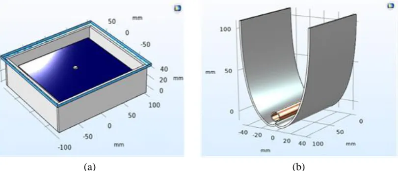
To validate the numerical apparatus an experimental set-up has been adopted. It consists of a stainless steel high-vacuum chamber, closed in the upper side by a clear glass, which can place a flat absorber suspended by four springs of negligible conductive thermal loss [11]. The light power is provided by a LED system. In figure 1 are depicted the sketches of the experimental arrangement (figure 1a: flat absorber in the vacuum chamber) and of the CPC under investigation (figure 1b: parabolic mirrors and the round tube).
2.1 Solar range: Ray Optics simulations
Ray Tracing technique has been employed to evaluate sunlight incident power distribution on the CPC walls (i.e. parabolic mirrors, pipe and glass) on the 2D model. To compare the results with flat absorber, the copper pipe was assumed to be coated with a selective solar absorber having the same optical characteristics of the flat absorber (solar absorptance, α: 0.95; thermal emissivity ε: 0.05 @ 100°C in air). A ray grid was placed at the CPC entry aperture and the incident angle for the incoming rays was changed from 0° to 30° of incidence angle. The optical efficiency of the CPC is calculated as fractions of the power incident on
0 5 10 15 20 25 30
0.0 0.2 0.4 0.6 0.8 1.0
Optical E
ff
iciency
Angle of Incidence (°)
(a) (b) (c)
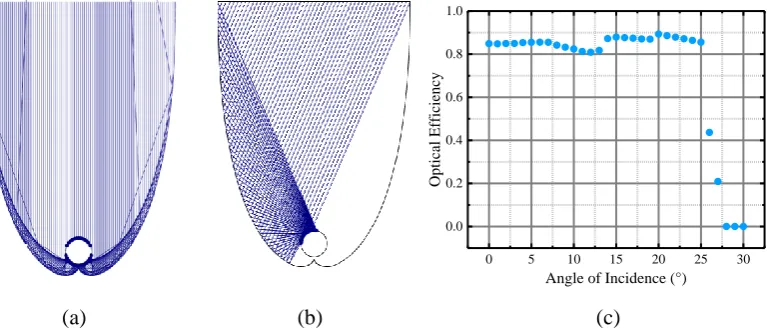
pipe divided by the power incident on the mirror aperture. It is reported in figure 2c as function of the incident angle (θi). It is worth to note that optical efficiency is almost constant
from 0 up to acceptance angle. This behaviour is not surprising because near the normal most rays undergo multiple reflections (see figure 2a) whereas close to the acceptance angle a single reflection is sufficient to focalize the rays on the central tube (see figure 2b); however, at high angle the effective impinged area is reduced by cosine of θi leading to the behaviour
reported in figure 2c.
The power fraction absorbed from various CPC components have been calculated up to the acceptance angle in the case of normal incidence (table 2) and they are normalized to the power entering the vessel (the glass transmittance has to be taken into account).
It is worth to note that the rays reflected by the absorber and by the mirror reaching the glass are mainly transmitted to the ambient (only a small fraction is reflected back to the vessel according to Fresnel law) whereas the fraction absorbed by the pipe can be calculated by the optical efficiency times the absorptance (0.95 in our case).
2.2 IR range: thermal radiation simulations
CPC components that reach high temperatures in operating conditions, can easily be modelled as bodies which emit energy uniformly in all directions according to the emission laws. When we aredealing with specular reflective surface, the thermal radiations should be treated with ray optics tool. Hence, the emitted power can be treated as a group of rays leaving the emitting surface in a hemispherical way. According to this perfectly specular approach the rays leaving the absorber are specularly reflected and distributed on the other CPC elements (figure 3c) and most of them are directed through the glass where they are absorbed due to the high glass emissivity in this IR region (ε = 0.89). The diffuse model (figure 3 b), instead assumes that the rays, emitted hemispherically from the surface, are diffused from the surfaces and therefore they are equally distributed on the CPC component.
The same approach should be used for all the panel elements that reach high temperatures, as their thermal radiation is not negligible. A tool offered by Comsol Multiphysics allows to define the fraction of diffuse and reflected energy from a surface. We performed numerical simulations imposing on all surface a 100% diffuse surface in one case and a 0.98 specular reflection in the other to highlight the possible differences between the two approaches. Geometry of the numerical model mimics a real panel configuration with parabolic mirrors suspended inside the vessel. A real panel can accommodate at least 6 CPC in its interior. Simulations have been conducted in 2D domain neglecting the finite size of the panel. Only the central mirror has been simulated: in this case on each side of the mirror there is another mirror having the same temperature of the central one. The back side of the parabolic mirrors and the vessel have their typical emissivity (ε = 0.05 for aluminium and ε = 0.15 for stainless steel).
Table 2. Ray optics analysis: absorbed fraction of solar incoming power for every CPC component.
CPC part Absorber Parabolic
Mirrors
Glass
Absorbed fraction of solar incoming power
On the glass and vessel external surface natural convection is imposed as a boundary condition. Sunlight incoming power is modelled as heat flux boundary condition: every CPC component receives the power fraction calculated by the ray optics analysis in visible range. Heat exchange with the heat transfer fluid is modelled with a heat flux boundary condition too. The efficiency curve is obtained changing the power subtracted from the circulating fluid in the pipe from 0 W up to available power. The same approach was used also for the flat panel: in this case we have an experimental set-up to verify our simulations and we performed the simulation using in the actual experimental conditions.
3. Results
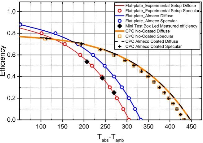
Our results are summarized in Figure 4. The efficiency has been calculated respect to the power incident on the glass (1000 W/m2) and the area has been assumed to be the absorber
area for flat absorber and the mirror aperture for the CPC. The model of the flat absorber is in agreement with experimental data (Black diamonds) for both, specular (red circles) and diffuse (red line) models. Since the glass is an extra-clear without anti-reflective (AR) coating, in this simulation we used a glass transmittance of 0.91 and the total efficiency is slightly lower than in the other cases where the glass is assumed to have a double AR coating with a transmittance of 0.95. The experimental data were obtained illuminating the absorber with different light power using a calibrated LED illumination system and recording the absorber stagnation temperature. In such configuration the power losses are equal to absorbed power and efficiency can be calculated, as reported in equation (1):
𝜂(𝑇𝐴𝑏𝑠) = 𝜏𝑔𝑙𝑎𝑠𝑠𝛼𝑆𝑢𝑛−
𝑃𝐿𝐸𝐷𝜏𝑔𝑙𝑎𝑠𝑠𝛼𝑆𝑢𝑛
𝑃𝑖𝑛𝑐 (1)
where Pinc = 1000 W/m2, τ
glass = 0.91 is the glass transparency, αSun = 0.95, PLED is the light
power provided by the calibrated LED System and Tabs is the stagnation temperature at a
given LED power .
The agreement between the two simulation models and between the models and the experimental data is satisfactory and we proceeded to analyse other configurations.
In the case of flat absorber, the use of double AR coating (transmittance 0.95) combined with a low emissivity material (ε = 0.02) on the inner side of the vacuum vessel can improve the performance of more than 10% at temperature higher than 200 °C (blue circles specular, blue line diffuse model). The slightly large power impinging on the absorber are responsible for
(a) (b) (c)
the 0.04 increase which is temperature independent. The temperature dependent improvement is due to low emittance surface on the vacuum vessel: the radiation emitted by the lower absorber face facing the vessel is reflected to the absorber and partially re-absorbed by it increasing performances. Due to the planar geometries the difference between diffuse and specular models are negligible.
In figure 4 we report also the results obtained by CPC simulations to compare them with the flat absorber.
100 150 200 250 300 350 400 450
0.0 0.2 0.4 0.6 0.8 1.0
Flat-plate_Experimental Setup Diffuse Flat-plate_Experimental Setup Specular Flat-plate_Almeco Diffuse
Flat-plate_Almeco Specular Mini Test Box Led Measured efficiency CPC No-Coated Diffuse
CPC No-Coated Specular CPC Almeco Coated Diffuse CPC Almeco Coated Specular
Efficienc
y
Tabs-Tamb
Figure 4. Thermal efficiency as function of the difference between the absorber and ambient temperature: simulation results for our planar experimental set-up (red line diffuse, red circle specular model); experimental efficiency of planar absorber in a vacuum box (black diamonds); simulation results for our experimental set-up equipped with double AR coating on glass and high reflectivity mirror on the internal surface (blue line diffuse, blue circle specular model); simulation results for a CPC inserted in the high vacuum collector (orange line diffuse, orange open square specular); simulation results of a CPC inserted in the high vacuum collector with all internal surfaces covered by high reflectivity mirror (black dashed line diffuse, black cross specular)
we have previously said we expect the specular model to be closer to the reality, however an experimental model is needed to validate our simulations in the CPC case.
4. Conclusions
We have simulated the behaviour of a flat solar absorber and a CPC inserted in a high vacuum vessel.
The simulations of the flat absorber reproduce the experimental results obtained by illuminating, with different known powers, the flat absorber using a calibrated LED system. Thermal efficiency was simulated assuming diffuse and specular reflections of the thermal emitted power and the results show no significant differences for the two models in the case of a planar absorber.
The efficiency is quite high already for our experimental set-up, however it can be improved by using a high reflectivity mirror on the vessel internal surfaces and glasses with double AR coating.
A further substantial improvement can be achieved inserting a CPC in the high vacuum vessel. In this case due to the presence of the high reflectivity mirror and its geometry, the two approaches, diffuse and specular, are no more equivalent and the diffuse model predicts an efficiency higher than the specular. Moreover, the use of high reflecting surfaces on the vacuum vessel does not produce any significant change in the thermal efficiency. The results were obtained using a commercial coating as selective solar absorber not optimized to work at high temperature. The use of a special designed coating, optimized to work at high temperature could further improve the performances.
Our simulations indicate that a CPC insert in a high vacuum panel can be an interesting solution to obtain high efficiency at temperature around 300°C.
5. References
[1] Buonomano A, Calise F, d’Accadia M D, Ferruzzi G, Frascogna S, Palombo A, Russo R and Scarpellino M 2016 Experimental analysis and dynamic simulation of a novel high- temperature solar cooling system Energy Convers. Manag. 109 19-39
[2] Tian M, Su Y, Zheng H, Pei G, Li G and Riffat S 2018 A review on the recent research progress in the compound parabolic concentrator (CPC) for solar energy applications Renew. Sustain Energy 82 1272-96
[3] Viebahn P, Lechon Y and Trieb F 2011 The potential role of concentrated solar power (CSP) in Africa and Europe—A dynamic assessment of technology development, cost development and life cycle inventories until 2050 Ener. Policy39 4420-30
[4] Ilic O, Bermel P, Chen G, Joannopoulos J D, Celanovic I and Soljacic M 2016 Tailoring high- temperature radiation and the resurrection of the incandescent source Nature Nanotech. 11 320-26
[5] Gu X 2014 Analysis of a New Compound Parabolic Concentrator-Based Solar Collector Designed for Methanol Reforming J Solar Energy Engin.136 041012-1 [6] Colina-Màrquez J, Lòpez-Vàsquez A and Machuca-Martìnez F 2010 Modeling of
direct solar radiation in a compound parabolic collector (CPC) with the ray tracing technique Dyna 77 132-40
[7] Carvalho M J, Collares-Pereira M, Gordon J M and Rabl A 1985 Truncation of CPC Solar Collectors and its Effect on Energy Collection Sol. Energy35 393-9 [8] De Witt D P and Richmond J C 1988 Theory and Practice of Radiation Thermometry
(New York: DeWitt and Nutter)
[9] Wen C D. Mudawar I 2006 Modeling the effects of surface roughness on the emissivity of aluminum alloys Int. J. Heat Mass Transfer49 4279-89
[10] Information on http://www.almecogroup.com/it