Aerospace Applications. (Under the direction of Dr. Abdel-Fattah M. Seyam).
High performance fibers are characterized by their high strength to weight ratio, and ability to withstand extreme temperatures and chemical exposure. These properties make high performance fibers excellent for use in applications requiring high tensile strength, high modulus, low weight, flexibility, and ability to withstand extreme temperatures. However, many high performance fibers lose strength and degrade when exposed to ultraviolet (UV) light.
Previously, 48,000 denier braids were sheathed with an approximate thickness of 0.40 mm using TiO2 at 3 levels (0, 5 and 10%) to be used as tendons for NASA Ultra Long Duration
Balloon (ULDB) missions. This experiment was successful in providing protection to the tendons, but further improvement in protection is needed in order to ensure that missions could be prolonged.
This research examines the use of industrially available sheathing methods to cover high performance braids to protect them from UV degradation. Polymeric sheaths extruded from Low Density Polyethylene (LDPE) with 3 different thicknesses (0.24, 0.33 and 0.42 mm) were developed with 3 levels % add-on (6%/6%, 10% and 13%) of 2 UV stabilizers (White CC® and nano-scale TiO2). The three levels of % add-on were 6% White CC®/6% TiO2,
UV stabilizer particulate in the LDPE, pellets were examined using TEM imaging. The pellets were also TGA tested to measure the UV stabilizer % add-on to ensure that the levels met the experimental guideline specifications. These braids and unsheathed braid were exposed to UV-B light for 6 days and analyzed for strength retention.
From the results, it was determined that reducing the sheathing thickness provides a way to reduce weight % add-on without damaging strength retention when sheathing has high % add-on of UV stabilizer. In this experiment, samples with 0.24 mm sheaths made from LDPE with 10% White CC® maintained strength best with 97.47% average strength retention. This is 29.12% greater than samples exposed to UV-B with no protective sheathing. Samples with 0.24 mm sheaths made from LDPE compounded with 13% TiO2 were also extremely effective in preserving strength during UV-B exposure with average strength retention of 97.27%. Though samples with 10% White CC® and 13% TiO2 offered comparable strength retention, samples with 13% TiO2 possessed higher weight add-on. This
was caused by the actual thickness of the samples with 13% TiO2 having an average
by
Courtney Anne Bolin
A thesis submitted to the Graduate Faculty of North Carolina State University
in partial fulfillment of the requirements for the degree of
Master of Science
Textiles
Raleigh, North Carolina 2013
APPROVED BY:
_______________________________ ______________________________ Dr. Yingjiao Xu Dr. Trevor Little
Committee Member Committee member
________________________________ Dr. Abdel-Fattah M. Seyam
DEDICATION
"Keep away from those who try to belittle your ambitions. Small people always do that, but
the really great make you believe that you too can become great."
- Mark Twain
BIOGRAPHY
Courtney Anne Bolin, whose middle name was chosen because of her mother’s love for Anne of Green Gables, was born in Kings Mountain, North Carolina on June 8th of 1989. Courtney was raised on her family’s small farm, which has been in her family since her Great Grandpa Bolin was forced out of Smyrna, South Carolina for being a moonshiner during prohibition. As a child she loved playing outside with her pets: 63 Black Angus cows and 1 Limousine bull, 17 Pigmy goats (her favorite one was named Scruffy), 31 chickens, 2 hound dogs and 1 grumpy cat (her least favorite pet).
After a high school career as a homeschooler, she decided to leave Kings Mountain in order to pursue an education at the College of Textiles at North Carolina State University in Raleigh. Here, she met many inspirational people and learned from an outstanding faculty. After an action-packed four years, she graduated with a Bachelor’s of Science in Textile Technology with a Concentration in Design. She believed that she had more to learn though and all it took was a comment from Dr. Tushar Ghosh (one of those outstanding faculty members) for her to discover that she was graduate school material.
ACKNOWLEDGMENTS
TABLE OF CONTENTS
LIST OF TABLES ... vii
LIST OF FIGURES ... viii
1. Introduction ... 1
2. Literature Review ... 3
2.1. NASA Balloon Project ... 3
2.1.1. Brief History of the NASA Balloon Project ... 3
2.1.2. NASA Scientific Balloon Program ... 4
2.1.3. Balloon Launch and Operation ... 7
2.2. High Performance Fibers, Photodegradation, Comparison ... 10
2.2.1. Aramid Fibers ... 11
2.2.2. Ultra High Molecular Weight Polyethylene ... 13
2.2.3. Thermotropic Liquid Crystal Polymers ... 15
2.2.4. Aromatic Heterocyclic Polymers ... 18
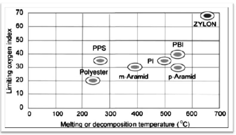
2.2.5. Comparison of High Performance Fibers ... 21
2.2.6. Photo Degradation in High Performance Fibers ... 22
2.2.7. Photo degradation of High Performance Fibers ... 23
2.3 Methods of UV Protection ... 30
2.3.1. Loading ... 30
2.3.2. Coating ... 31
2.3.3. Sheathing ... 34
2.3.3.1. Sheaths from Aluminum Foil, Teflon, Thin Flexible Films with Carbon Black ... 35
2.3.3.2. Sheathing with a Porous Membrane Made by Film Casting Technique ... 38
2.3.3.3. Electrospun Polyurethane Sheaths ... 43
2.3.3.4. Woven Sheathing ... 49
2.3.3.5. Extruded LDPE Sheaths ... 49
3. Research Objective ... 52
4. Experimental ... 54
4.1. Protection of High Performance Fibers Using Extruded Sheathing ... 54
4.1.1. Materials ... 54
4.1.2. Compounding and Sheathing Extrusion ... 55
4.1.3. Experimental Design ... 56
4.2. Testing and Evaluation ... 58
4.2.1. TEM imaging of the sheath material loaded with TiO2 ... 58
4.2.2. TGA analysis ... 58
4.2.3. Weathering (UVB only) ... 59
4.2.4. Tensile Properties Testing ... 61
4.2.5. Sheath Thickness and weight measurements ... 64
5. Results and Discussion... 66
5.1. TEM analysis of LDPE pellets ... 66
5.2. TGA Analysis of LDPE pellets ... 68
5.4. Analysis the effect of UV stabilizer type, % content and sheath thickness on
tensile strength retention for 72K braids ... 75
5.5. Analysis the effect of UV stabilizer type, % content and sheath thickness on tensile strength retention for yarns unraveled from 72K denier braids ... 77
5.6. Comparison of 48,000 denier braids to 72,000 denier braids... 80
6. Conclusion and Future Work ... 85
APPENDICES ... 91
Appendix A ... 92
Appendix B ... 107
Appendix C ... 123
Appendix D ... 139
LIST OF TABLES
Table 1. Properties of Various Grades of Kevlar® (14) ... 12
Table 2. Tensile properties of Various Grades of Nomex® (15) ... 13
Table 3. Physical Properties of Spectra® fiber 900 (17) ... 14
Table 4. Physical Properties of Spectra® fiber 1000 (18) ... 14
Table 5. Physical Properties of Spectra® fiber 2000 (19) ... 15
Table 6. Mechanical properties of different types of UHMWPE (22) ... 17
Table 7. Properties of Zylon® PBO Fiber (23) ... 18
Table 8.Comparison of high performance fibers (22) (25) (26) ... 22
Table 9. Fibers selected for study (32) ... 32
Table 10. Fibers selected for study ... 35
Table 11. Combinations of fibers and coatings, and results of tensile testing ... 37
Table 12. Tensile strength loss of the PBO braids before and after UV exposure (13) ... 51
Table 13. Experimental Design of Extruded Sheathing ... 57
Table 14. Average Content and Add-On of UV Stabilizers of TiO2 in LDPE Pellets with TGA ... 69
Table 15. Average Content and Add-On of UV Stabilizers of TiO2 in LDPE Pellets with muffle Furnace ... 72
Table 16. Thicknesses and Weights of 72,000 Denier Tendons ... 75
Table 17. Strength Retention of Yarns Removed from 72,000 Denier Braids After 6 Days Exposure ... 79
LIST OF FIGURES
Figure 19. UV-VIS light transmittances of blank PU membrane in terms of number (37) .... 42
Figure 20. UV-VIS light transmittances of PU membrane containing 4% TiO2 (37) ... 42
Figure 21. Schematic of Electrospinning Method (40) ... 43
Figure 22. UV transmission of layered fabric systems and control fabric (41) ... 45
Figure 23. Schematic of electrospun sample used for testing UV resistance (32) ... 46
Figure 24. Group I sample after 6 days UV exposure (32) ... 47
Figure 25. Tensile strength of the PBO yarns with no protection and sheathed by group I, II, III after 6 days of UV exposure (12) ... 48
Figure 26. Structure of the 2x2 Construction PBO Braid ... 54
Figure 27. QUV/se Accelerated Weathering Tester at BRDL ... 60
Figure 28. Tendons Ready for Exposure in QUV/se Accelerated Weathering Tester ... 61
Figure 29. NASA splicing measurements ... 62
Figure 30. Instron 8800 Used at BRDL for Tensile Testing of Braids ... 63
Figure 31. MTS Q-Test/5 Used at NCSU for Tensile Testing of Yarns ... 64
Figure 32. TEM images of LDPE with 13% TiO2 before reworking ... 67
Figure 33. TEM images of LDPE with 6% White CC and 6% TiO2 ... 67
Figure 34. TEM images of LDPE with 13% TiO2 after reworking ... 68
Figure 35. TGA % Add-On Weight Analysis of LDPE Pellet with 13% TiO2 ... 70
Figure 36. TGA % Add-On Weight Analysis of LDPE Pellet with 13% TiO2 and 6% White CC®/6% TiO2 pellets ... 71
Figure 37. Weight % Add-On of Sheathing to 72,000 Denier Braids ... 74
Figure 38. Strength Retention of Tendons after being exposed to UV-B Light for 6 Days ... 77
1.
Introduction
High performance fibers are characterized by high strength and the ability to withstand extreme temperatures and chemical exposure. These properties make high performance fibers excellent for use in applications requiring high tensile strength, high modulus, low weight, flexibility, and ability to withstand extreme temperatures. Examples of high performance fibers commercially available include Kevlar®, Spectra®, Nomex®, Vectran®, Dyneema®, and Zylon®. Current applications of these fibers include bulletproof vests, firemen’s turnout jackets, ropes and cables, and lightweight preforms for composites to replace heavy metals.
Many high performance fibers lose strength and degrade with exposure to ultraviolet (UV) light. UV degradation is currently a limiting factor for these fibers and their usage is limited to applications where existing protective measures provide adequate UV protection. It is critical to improve methods of protection from solar damage, especially UV radiation to allow utilization of the outstanding characteristics in settings where they will come into contact with both visible and UV light. The development and implementation of more efficient methods of UV protection will maintain the exceptional qualities of high performance fibers and allow them to be used much more widely.
research fields as an effective way to collect data in support of space and earth research. Scientific balloon missions are currently limited in duration by tendons, which are made from high performance fibers, failure due to UV degradation. Stabilizing the tendons so that the missions can achieve longer orbit times before failure will allow the collection of data over longer periods of time. Due to its low creep, high strength to weight ratio, and relatively low cost, NASA has been investigating the use of p-phenylene-2,6-benzobisoxazole (PBO), which is commercially known as Zylon® in tendons for balloon applications. Literature disclosed that Zylon® fiber loses substantial strength upon exposure to UV light. Attempts, which will be addressed later, to protect the fibers from UV radiation revealed some success, but more improvements are needed in order for the Zylon® fibers to be used as tendons for scientific balloon and other industrial applications where UV exposure is an issue with current protection methods.
2.
Literature Review
2.1.NASA Balloon Project
2.1.1. Brief History of the NASA Balloon Project
The National Science Foundation established the Columbia Scientific Balloon Facility (CSBF) in Boulder, Colorado in 1961. The facility was moved to Palestine, Texas in 1963 and was designated as the National Scientific Balloon Facility in January of 1973 (1). The sponsorship of the facility was transferred to the National Aeronautics and Space Administration (NASA) in 1982 (2) and it became a separate entity under the University Corporation for Atmospheric Research.
2.1.2. NASA Scientific Balloon Program
The NASA Scientific Balloon Program is a suborbital space flight program that serves primarily to support the space and earth sciences and research activities. They have contributed to scientific discoveries by acting as carriers for scientific instruments. The scientific balloons function in the same way as an orbiting satellite or the Space Shuttle, but at a much lower cost (4). Balloons’ added benefits include the ability to carry large heavy payloads with a lead time as short as six months after approval for mission support, and the recovery of balloon instruments can be recovered after missions and flown again within a few days or weeks (4). Balloons can be launched from many locations around the world, making them an effective method for performing scientific investigations in the near space environment above 99.5% of the Earth’s atmosphere (4). Data collected during missions includes information that has been used to answer questions about the universe, atmosphere, the Sun and space environment (3). Current and historical payloads include telescopes that cover a wide range of the light spectrum. These balloon borne spectrometers are flown to provide information about the atmosphere, the universe, the Sun, and the near-Earth space environment (4). Balloons also serve as high altitude platforms for drop tests to study aerodynamic characteristics of future space and terrestrial vehicles and decelerators, and as a test platform to qualify and calibrate new instruments and subsystems prior to their use in more complex or expensive missions (4).
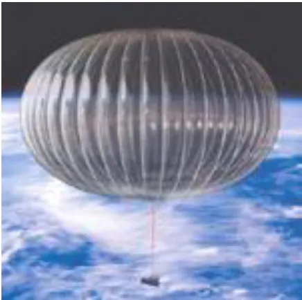
ultra-long duration (ULDB) (3). Conventional ballooning utilizes a zero pressure (ZP) type balloons where the differential pressure at the base of the balloon is zero. Mid-latitude missions with this type of balloons are typically short, 18 to 48 hours. However, when these balloons are flown at the poles, where the day/night excursion is minimized, they can last for several weeks at altitude, and hence are called LDB missions. On the other hand, ULDB at mid-latitudes requires a super pressure balloon (SPB) (See Figure 1) design that maintains a constant volume throughout the mission. The SPB has a distinct pumpkin shape, which comes from pressure on the load carrying members (tendons) and gas barrier (Polyethylene) film (See Figure 2). The flight time for the SPB is intended to reach 100 days at mid-latitude with minimized variation in altitude (See Figure 2).
Figure 2. Contrast of altitude consistency for Super-Pressure and Zero-Pressure Balloons (5)
instrument or experiment (4). The total suspended load from a scientific balloon can weigh as much as 3,629 kilograms (8,000 lbs) and can be lifted to an altitude of 35,966 meters (118,000 ft); however, balloons can achieve higher altitudes with lighter payloads. While the basics of ballooning remain unchanged over the decades that they have been used to conduct scientific studies, balloons have increased in size and their dependability has greatly improved (4).
NASA missions have provided tremendous contributions in many scientific fields, which include cosmic microwave background (CMB) anisotropy measurements, studies of antiprotons in the cosmic rays, gamma-ray lines from the Supernova and many others (6). Therefore, continued research and improvement to ballooning remains critical to ongoing and future projects in many scientific fields.
2.1.3. Balloon Launch and Operation
minimize impact and it is recovered. The balloon is disposed of after recovery, but the payload can be used in future missions.
NASA normally supports 15 to 20 scientific balloon flights annually and the demand is rising. Balloons allow payloads to be flown without the vibrations and G-forces associated with rockets, and the payload is recoverable, which allows for multiple flights of the same instruments. Antarctica is a premier flight location because LDB flights have flown for over 41 days during the Antarctic Austral Summer. During this time, the balloons experience less severe diurnal changes than those encountered at mid-latitudes. The constant sunlight allows observation of the Sun for a full solar rotation, and the orientation of Earth in space allows valuable celestial observations.
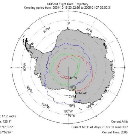
To date, NASA has launched six Cosmic-Ray Energetics And Mass (CREAM) missions from the National Science Foundation’s McMurdo Station located in Antarctica. CREAM-I launched on December 14 of 2004 (7) and travelled for 41 days and 22 hours before landing, which makes CREAM-I the longest orbiting LDB mission to date (the record length of an ULDB mission using a SPB is held by Super-TIGER at 55 days, 1 hours and 34 minutes). During this time CREAM circled the South Pole 3 times (See Figure 3) (7).
launched December 19 of 2007 and orbited 29 days; CREAM-IV launched December 19 of 2008 and orbited 19 days and 13 hours; CREAM-V launched December 1 of 2009 and orbited 37 days and 10 hours; and CREAM-VI launched December 21 of 2010 and orbited 5 days and 16 hours (8).
Figure 3. CREAM Track of South Pole (8)
was not recovered until January 11, 2011 meaning that it was left subject to environmental exposure for approximately 15 days before retrieval (2).
Previous BLAST missions include: BLAST 2003 (New Mexico Campaign) which was the engineering flight that orbited for 27 hours, BLAST 2005 (Sweden Campaign) which was the first successful long duration flight launched from Kiruna, Sweden and flew 4 days, and BLAST 2006 (Antarctica Campaign) which was launched from McMurdo Station and orbited for 11 days (9).
Some of the other LDB missions carried out include Balloon Array for Radiation-belt Relativistic Electron Losses (BARREL), Antarctic Impulsive Transient Antenna (ANITA) and Balloon Experiment with a Superconducting Spectrometer (BESS).
2.2.High Performance Fibers, Photodegradation, Comparison
2.2.1. Aramid Fibers Kevlar
Kevlar® is a registered trademark of DuPont™ for a para-aramid synthetic fiber that is comparable to Technora® made by Teijin™. The fiber’s strength comes from its structure of long polymeric chains that are parallel in orientation with intra-molecular bonds and phenyl stacking interactions (10). It is highly crystalline, lightweight, flexible and dimensionally stable, which makes it desirable for high strength ropes and cables (11). Kevlar® is five to eight times stronger than steel when compared weight for weight (11) and has an elastic modulus four times higher than nylon (12). The fiber’s high strength and high heat resistance extends its life span by reducing breaks, and reduces the cost of maintenance over its service lifetime. Kevlar® also maintains its properties at cryogenic temperatures and does not become brittle in extreme cold (13), which allows the fiber to be used in dry and cold conditions.
Kevlar® is best known for its application in bullet proof vests, but it has also been used to reinforce landing cushions of the Mars Pathfinder, and in space shuttles to help protect them from orbital debris (11).
offers the highest strength to weight ratio and lowest elongation. Properties of the various grades of Kevlar are listed in Table 1.
Table 1. Properties of Various Grades of Kevlar® (14)
Kevlar® Grade 29 49 68 149
Density (g/cc) 1.44 1.44 1.44 1.47
Tensile Modulus (g/ den) 555 774 715-780 1100
Tenacity (g/den) 22 22 24 19
Tensile Elongation (%) 4 2.5 2.9 1.5
Nomex®
Table 2. Tensile properties of Various Grades of Nomex® (15)
Product Type 430 Type 430 Type 450 Type
455/462
Density (g/cc) 1.38 1.38 1.37 -
Initial Modulus (g/den) 94 85 - -
Tenacity (g/den) 5 4.9 2.9 2.6
Elongation at break (%) 30.5 31 22 21
2.2.2. Ultra High Molecular Weight Polyethylene Spectra®
Table 3. Physical Properties of Spectra® fiber 900 (17)
Physical Properties
Spectra® fiber 900
Denier/ Filaments 650/ 60 1200/120 2400/240 4800/480
Density (g/cc) 0.97 0.97 0.97 0.97
Modulus (g/den) 920 850 915 885
Tenacity (g/den) 30.5 30 29.5 25.5
Elongation (%) 3.6 3.9 3.9 3.6
Applications of Spectra® 1000 include ballistic vests and helmets used in military and police applications, composite armor for aircrafts and vehicles, marine lines and nets, industrial cordage and slings, sailcloth and cut-protection products. Table 4, summarizes the physical properties of Spectra® 1000.
Table 4. Physical Properties of Spectra® fiber 1000 (18)
Physical Properties
Spectra® fiber 1000
Denier/ Filaments 650/120 1300/240 1600/240 2600/480
Density (g/cc) 0.97 0.97 0.97 0.97
Modulus (g/den) 1175 1150 1170 1135
Tenacity (g/den) 36 35 35.5 34
Spectra® 2000 applications include flexible and ultra-lightweight panels for police and military ballistic vests, specialty aerospace applications, superfine fishing line and kite string. Table 5, summarizes the physical properties of Spectra® 1000.
Table 5. Physical Properties of Spectra® fiber 2000 (19)
Physical Properties
Spectra® fiber 2000
Denier/Filaments 100/ 40 130/ 40 180/50
Density (g/cc) 0.97 0.97 0.97
Modulus (g/den) 1450 1320 1350
Tenacity (g/den) 39 38 38
Elongation (%) 3 2.8 2.9
2.2.3. Thermotropic Liquid Crystal Polymers Vectran®
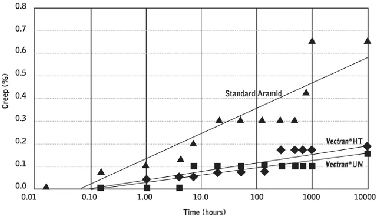
Vectran® also exhibits good creep resistance when exposed to long-term static loading (20), which is critical for long-term load bearing. Figure 4 contrasts creep percentage of Vectran® HT and Vectran® UM with a standard aramid.
Figure 4. Creep Behavior at Ambient Temperature (30% of Break Load) (20)
Dyneema
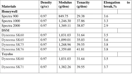
various types of Dyneema® are compared to various Spectra® fiber classes. The comparison shows that Dyneema® fibers share the same density, but have a higher modulus and tenacity when compared to a similar class of Spectra®. This means that Dyneema® could offer the same strength as Spectra® with lower weight add-on.
Table 6. Mechanical properties of different types of UHMWPE (22)
Materials Density (g/cc) Modulus (g/den) Tenacity (g/den)
Elongation to break,%
Honeywell
Spectra 900 0.97 849.75 29.38 3.6
Spectra 1000 0.97 1,246.30 37.86 3.3
Spectra 2000 0.97 1,369.11 38.87 2.9
DSM
Dyneema SK60 0.97 1,031.03 31.64 3.5 Dyneema SK65 0.97 1,099.01 35.03 3.6 Dyneema SK75 0.97 1,268.96 39.55 3.8 Dyneema SK76 0.97 1,359.60 41.81 3.8
Toyobo
2.2.4. Aromatic Heterocyclic Polymers Zylon® (PBO)
Zylon® is the trade name used to represent poly(p-phenylene-2,6-benzobisoxazole (PBO) produced by Toyobo Corporation™. The fiber is commercially available in As Spun (AS) and High Modulus (HM) forms. HM Zylon® is made by heating and drawing AS Zylon® to create a slightly denser fiber with a higher tensile modulus and lower elongation. PBO has a rigid chain molecular structure, which results in its high tensile strength. Other characteristics of the fiber include excellent impact absorption and good thermal stability. The properties of Zylon® are listed in Table 7.
Table 7. Properties of Zylon® PBO Fiber (23) Zylon® PBO Fiber
As Spun High Modulus
Denier 1.5 1.5
Density (g/cc) 1.54 1.56
Tensile Modulus (g/den) 130.18 194.70
Tenacity (g/den) 4.18 4.18
Elongation at Break (%) 3.5 2.5
of its breaking load. It was found that the non-recoverable strain of HM Zylon® was less than 0.03% (23). Results from testing can be seen in Figure 5.
Figure 5. HM Zylon® creep parameter under 50% of breaking strength (23)
Figure 6. Comparison of Zylon® and other high performance fibers in tenacity and modulus (24)
2.2.5. Comparison of High Performance Fibers
Table 8.Comparison of high performance fibers (22) (25) (26)
2.2.6. Photo Degradation in High Performance Fibers
Photo degradation is a naturally occurring problem with many high performance fibers. It is caused when fibers are exposed to solar radiation, which results in weakening of the fiber due to cross-linking and chain scission reactions.
UV radiation occurs at wavelengths between 290-400 nm and makes up 6% of total solar radiation (27). The stratospheric ozone blocks radiation with wavelengths of 290 nm or less leaving visible (52%) and infrared (42%) radiation. Many polymers' bonds begin to
Fiber type Density (g/cc)
Elongation at break (%) Breaking tenacity (g/den) Inital modulus (g/den) Moisture regain (%) Melting point (°C)
Nylon 1.14 17 to 45 4.0 to 7.2 45 2.8 to 5.0 NA
Kevlar® 29 1.44 3.6 23 555 7 427
Kevlar® 49 1.44 2.4 23.6 885 3.5 427
Nomex® 1.38 28 4.9 95 4.5 371
Spectra® 0.97 2.7 to 3.5 26 to 34 1200 < 0.1 147
Zylon® AS 1.54 3.5 42 1303 0.6 650
Zylon® HM 1.56 2.5 42 1949 0.6 650
Vectran®
breakdown under radiation (100-400 nm), which results in a change of chemical and mechanical properties such as the reduction of tenacity. The physical changes that occur depend on a combination of UV radiation, oxygen, moisture, wind-borne abrasives and other environmental components (28). Solar radiation, air and pollutants usually initiate photo degradation and the process is often enhanced by organic solvents, extreme temperatures and mechanical stress (29). Photo degradation causes a reduction in molecular weight of the polymer with bond scission, which further alters the mechanical properties of the fibers (28).
The deterioration of the fibers increases the chance of failure during use. This can be prevented by adding UV stabilizers to a polymer or using a sheath to cover the braid to absorb the UV radiation and dissipate the energy as a low level of heat. UV exposure, particularly UV-B exposure, is an increasing concern in Antarctica due to a forming hole in the ozone (30). The following sections deal the degree of photo degradation in various high performance fibers.
2.2.7. Photo degradation of High Performance Fibers
Kevlar®
(31). The degradation of Kevlar® is not dependent on moisture or atmospheric contaminants; however oxygen is required for the fiber to degrade (13). Kevlar® is especially sensitive between 300-450 nm (See Figure 8), which means Kevlar® also degrades under some wavelengths of visible light.
Figure 8.Overlap of the Absorption Spectrum of Kevlar® with the Solar Spectrum (13)
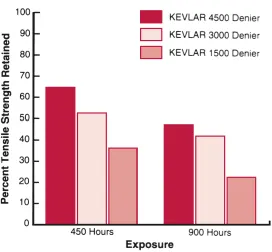
larger cords or braids where damaged fibers make up a only small fraction of the total denier. Figure 9 shows the tensile strength retention of Kevlar® at 1500, 3000, and 4500 denier after exposure to 450 and 900 hours of exposure. After 900 hours of exposure, 4500 denier Kevlar® retained roughly twice the strength compared to 1500 denier Kevlar®.
Nomex®
Nomex® is also impacted by prolonged exposure to both UV and visible light. During exposure to visible light Nomex® begins to discolor and lose its mechanical properties. The degree to which mechanical properties are lost depends on wavelength, exposure time, radiation intensity and the geometry of the fiber (15). In order for degradation to occur the fiber must be exposed to light at a wavelength that can be absorbed into the fiber (most damaging to Nomex® is 360 nm) and the radiation must have energy capable of breaking bonds.
Figure 10. Strength Retained by 200 Denier Nomex® Yarn after Exposure in Weather-O-Meter (15)
Vectran®
Vectran® fibers lose a large percentage of their strength when exposed to UV light. When the fiber was exposed to xenon light in a “Weather-O-Meter” tester, it retained 69% of its strength after 24 hours, 22% after 96 hours and 13% after 144 hours (32).
Zylon® (PBO)
Figure 12. Strength loss in Zylon® and other high performance fibers due to UV exposure (35)
Other studies of Zylon® show more accelerated aging using a “Weather-O-Meter" for testing. In one study (32), unprotected PBO retained 37% of its strength after 24 hours of UV exposure, 15% of its strength after 96 hours and 12% after 144 hours of exposure (32).
2.3 Methods of UV Protection
2.3.1. Loading
a UV stabilizer (often antioxidants or pigments) is to reduce the damage caused by UV radiation to the fiber by absorbing or scattering the radiation. However, loading high performance fibers with UV stabilizer is often difficult because of the harsh conditions of spinning processes. Compounding the polymers with UV stabilizers can also result in loss of strength and reduction in elongation at break. Polyester loses 6% of its elongation at break with just 1% of TiO2 (a commonly used UV stabilizer) added to the fiber (36). TiO2 also
causes the formation of solid crystals, which result in development of weak points within the fibers (12).
2.3.2. Coating
The photostability of fibers can also be improved by coating with chemicals containing UV stabilizers. This coating process is performed by feeding the yarn or fabric through a finish application system, after the coated yarns or fabric are then passed over a heated drum to heat-set the outer surface.
Table 9. Fibers selected for study (32)
Fiber Tex/ Number of Filaments Manufacturer
Zylon® HM 166.67/996 Toyobo
Vectran® T-97 166.67/300 Celanese Corporation
Kevlar® 49 157.78/1000 DuPont Textile Fibers
Figure 13. Process used for chemical coating (32)
Lowilite® samples) lost 50-60% tensile strength after 24 hours and 70-90% tensile strength after 96 hours. Zylon® treated with carbon black and Tinuvin® 234 lost 35 and 37% respectively. The poor strength retention was associated to the seeping of the chemical coating into the braids and not remaining on the outer surfaces of the braid (32).
Another study (12) showed that a Kevlar® braid with TiO2 maintained its strength better than
an uncoated braid; however, the coated braid only retained 64% of its strength after 150 hours of exposure (Figure 14).
2.3.3. Sheathing
Sheathing is another method that has been investigated to reduce the damage that occurs to high performance fibers when they are exposed to UV light. Sheaths made of various materials have been used to form a protective cover around braids (2, 12, 32, 37). In previous works (13, 33, 38) materials like aluminum foil, Teflon, thin flexible films containing carbon black, and UV stabilizers have been used to sheath high performance fibers to protect them from UV radiation. In addition to the various materials used for sheathing, different methods of sheathing have also been investigated including extrusion, film casting (porous membranes), electrospinning and woven sheathing (12, 32, 36, 37, 38).
2.3.3.1. Sheaths from Aluminum Foil, Teflon, Thin Flexible Films with Carbon Black
Three high performance (See Table 10) fibers were selected for comparison of performance after exposure to UV light (32). , film casted coverings containing UV blockers were used to reduce damage.
Table 10. Fibers selected for study
Fiber Tex/ Number of Filaments Manufacturer
Zylon® HM 166.67/996 Toyobo
Vectran® T-97 166.67/300 Celanese Corporation
Kevlar® 49 157.78/1000 DuPont Textile Fibers
and sheathings can be seen in Table 11 with the tensile strength results after exposure to UV light.
Table 11. Combinations of fibers and coatings, and results of tensile testing Yarn and Finish
Type/Protection System
Tensile Strength (g/denier)/% Tensile Strength Loss 24 Hours 96 Hours 144 Hours 168 Hours Zylon®Untreated 12.21/62.64 4.89/85.04 3.87/88.16 --
Zylon®BP I (1 Layer) 27.85/14.78 -- -- --
Zylon®BP I (2 Layers) 30.45/6.82 -- -- --
Zylon®BP I (3 Layers) 30.65/6.21 -- -- --
Zylon®BP II (1 Layer) 31.92/2.33 31.57/3.40 -- 31.53/3.52 Zylon®BP III (1 Layer) 31.45/3.76 32.99/-0.95 -- 31.97/2.17
Zylon®Teflon (1 Layer) 18.01/44.89 -- -- --
Zylon®Teflon (2 Layers) 17.19/47.39 -- -- --
Zylon®Al foil (1 Layer) 28.45/12.94 -- -- --
Zylon®Al foil (2 Layers) 32.07/1.86 -- -- --
Zylon®Al foil (3 Layers) 30.06/8.02 -- -- --
Zylon®BP I + Al foil 31.57/3.39 32.26/1.29 -- 31.56/3.42 Zylon®BP I + Teflon 31.25/4.38 30.75/5.91 -- 30.40/6.98 Zylon®Teflon + BP I 31.67/3.09 29.52/9.67 -- 26.06/20.26
2.3.3.2. Sheathing with a Porous Membrane Made by Film Casting Technique
Protective porous membranes made from polyurethane loaded with TiO2 nanoparticles have
been used to protect PBO braids from photo degradation (37). Porous membranes covering individual polymer fibers are traditionally used in textiles (e.g. nylon and polyester) to offer UV protection (39), but to create an effective and lightweight sheathing the process can be performed on braids rather than individual yarns to decrease added weight while still providing efficient UV protection
Figure 15. FESEM cross-section image of blank PU membrane prepared by evaporation technique (37)
The higher porosity in the case of membranes formed using the coagulation method decreased the transmittance of UV and visible light as shown in Figure 17.
Figure 17. UV-VIS light transmittances of blank PU membrane (37)
The higher porosity achieved using the coagulation method also results in a lighter sheath covering. .The coagulation method was further investigated by evaluating the effect of adding TiO2 nanoparticles to the membrane. Figure 18 shows that adding TiO2 nanoparticles
resulted in a decrease in membrane density (or increase in porosity). When the TiO2 was
Figure 18. Density of coagulated PU membrane loaded with different % TiO2 nanoparticles as compared to membrane prepared by evaporation method of membrane layers (37)
Increasing the number of layers of the coagulated sheath with no TiO2 decreases
transmittance of both UV and visible light. When 4%TiO2 was used in the coagulated
sheathing material the decrease of transmittance was far greater (Figure 19 and Figure 20). Figure 20 also shows near complete blocking of UV light and also the low impact of number of layers when using 4% TiO2. Therefore, the numbers of layers used for protection could be
Figure 19. UV-VIS light transmittances of blank PU membrane in terms of number (37)
Though this technique provides promising results the technique is not commercially available for large-scale production.
2.3.3.3. Electrospun Polyurethane Sheaths
Nanofiber webs which are produced using electrospinning process, have also been used as protective sheath. Electrospinning process uses electrostatic forces to spin fibers by charging the polymer solution at an increasing voltage until it exceeds the surface tension at the tip of the spinneret and the polymer solution is ejected to form nanofiber web with random fiber orientation. A schematic of the electrospinning process is shown in Figure 21. The large surface area provided by the nanofiber web along with its light weight, small thickness, and flexibility, makes it an excellent material for UV protection of high performance fibers (40, 41).
Figure 22. UV transmission of layered fabric systems and control fabric (41)
Another study (12) examined the UV protection performance of high performance fiber (PBO) braids covered with electrospun layers of polyurethane containing UV blocker (TiO2
nanoparticles). For the electrospinning process several polymer solutions were prepared by dissolving the polymer in N, N-Dimethylacetamide until 11% concentrate by weight was achieved. Polymer solutions containing three levels of TiO2 (0, 1, 2 % by polymer by
g/m of braid (group A, group B, and group C respectively). Electrospun layers were created and then secured to braid with tape (See Figure 23).
Figure 23. Schematic of electrospun sample used for testing UV resistance (32)
After UV exposure the samples were tested for tensile strength retention (12), and it was found that group A (1.10g/m of braid) had the highest transmittance, group B (2.29 g/m of braid had slightly lower retention than group A, and group C (3.00 of braid) had the lowest retention of all. This confirms that increasing the fiberweb density of electrospun polyurethane layers provides better protection and increases strength retention.
exposure. In addition to brittleness and yellowing, the electrospun polyurethane layers used in Group I also became transparent after 6 days of exposure (See Figure 24).
Figure 24. Group I sample after 6 days UV exposure (32)
In order to investigate the strength loss caused due to the UV_VIS exposure, 1% TiO2
Figure 25. Tensile strength of the PBO yarns with no protection and sheathed by group I, II, III after 6 days of UV exposure (12)
applications further studies are required improvement in thickness uniformity and development of viable commercial production method.
2.3.3.4. Woven Sheathing
Woven sheaths have been applied using a woven fabric sheath to protect high performance fiber braids from UV degradation. It was found that the woven sheathing method did not offer adequate coverage and allowed high UV transmittance which causes damage to the braid (37). Research on this method of sheathing was discontinued in favor of other sheathing methods, which offered better protection (37).
2.3.3.5. Extruded LDPE Sheaths
Various extruded polymeric film to coat PBO braids intended for use as load-bearing tendons of scientific balloons have been studied to evaluate their UV-VIS protection performance (12). The study involved extrusion of sheath from polyethylene compounded with different levels of UV stabilizers like TiO2 and White PE CC®. The polyethylene was chosen because
its properties are suitable for high altitudes and its inherent resistance to UV degradation. The content levels of UV blockers used in the study included 0%TiO2, 5% TiO2, 10% TiO2
and 12% White PE CC®. The sheathed and unsheathed braids were exposed to UV light for 0,1,2,3,4 and 6 days.
The results of UV-VIS transmittance testing of four types of polymeric films showed that in all the polymeric films samples that were loaded with a UV blocker transmission of UV-A, UV-B and UV-C was less than 1%. The study also found that the lowest transmittance was the in case of polyethylene film loaded with 12 % White PE CC® which indicated that the polyethylene extruded film loaded with 12% White PE CC® would provide highest protection against the UV-VIS radiation.
The study also investigated the strength loss in sheathed and unsheathed PBO braids after incremental UV-VIS exposure durations from 1 to 6 days. The strength loss results (
Table 12) show that after 6days of UV-VIS exposure maximum tensile strength was retained by the PBO braid sample using sheathed with polyethylene film loaded with 10% TiO2,
Table 12. Tensile strength loss of the PBO braids before and after UV exposure (13)
Exposure Time (Day)
Tensile Strength Loss (%) No
Protection
Unloaded PE
12% White PE CC®
5% TiO2
10% TiO2
0 0.00 0.00 0.00 0.00 0.00
1 48.23 35.25 10.35 12.98 14.01
2 56.88 40.16 26.79 22.65 15.25
3 63.05 47.25 26.67 29.90 21.62
4 65.86 50.41 29.82 36.37 22.81
6 72.44 59.07 36.75 42.56 29.35
The study also found that increasing the amount of TiO2 from 5% to 10% in the sheathing
material increases the strength retention by about 13% after 6 days of exposure. Samples with White PE CC® provided lowest transmittance of visible light, but samples retained less tensile strength than with samples with TiO2. Higher levels of TiO2 in sheathing should be
3. Research Objective
High performance fibers have characteristically superior mechanical properties and high resistance to extreme conditions. As a result, they have been used in countless applications, including bulletproof vests, firemen’s turnout jackets, ropes and cables, and lightweight preforms for composites to replace heavy metals.
However, it is also known that high performance fibers undergo severe degradation when exposed to UV radiation, which makes these fibers underperform in applications that involve exposure to UV radiations. By further developing UV protective coverings the desirable properties of high performance fibers that are depleted by UV radiation would be maintained when exposed to spectral radiation.
sheathing method remains unexplored. Sheath thickness and weight add-on of UV stabilizer can be manipulated in order to achieve better results. Research has been inspired by NASA’s need to improve tendons used in the Scientific Balloon Program to achieve their goal of 100 or more days of orbit time; however, findings are of paramount importance to many other applications where high performance fibers are exposed to light. In recognition of this research is required to investigate the various materials and structures involved in the sheath extrusion method to obtain a clear understanding of its UV protective performance.
Recognizing the need for continued research and improvement of UV resistant coverings for high performance fibers, an investigation was conducted to:
1. Understand the effects of braid structural properties in maintaining the strength of high performance fibers in applications where degradation from light may occur.
4. Experimental
4.1.Protection of High Performance Fibers Using Extruded Sheathing
4.1.1. Materials
Braid
In this research, braids of 48,000 denier (16 carriers, 2 strands per carrier, 1500 denier/996 filaments per strand, HM Zylon® (PBO) fiber) and 72,000 denier (16 carriers, 3 strands per carrier, 1500 denier/996 filaments per strand, HM Zylon® (PBO) fiber) hollow braids with a 2x2 construction were manufactured at Cortland Cable Company in Cortland, New York. For ULDB applications, these braids act as the load bearing tendons in ballooning missions. There are 290 tendons per balloon and each tendon is required to load 725 kg (1,600 lbs) evenly for a goal of 100 days. Figure 26 shows the braid structure.
Sheathing Material
A low density polyethylene (LDPE) in pellet form was selected to form the sheathing of the braids. Sheathing was extruded at three thicknesses around the braids: 0.24mm, 0.33mm and 0.42 mm.
UV Stabilizers
Rutile TiO2 nanoparticles (supplied by Nanostructure and Amorphous Materials, Inc.) and
PE White CC® (Supplied by PolyOne Co.) were used as the UV stabilizers and were compounded with LDPE to form the sheathing material. Stabilizers were used individually and in combination at different levels (by weight add-on %). The material safety data sheets for TiO2 from Nanostructure and Amorphous Materials, Inc. and White CC® from PolyOne
Co. are provided in Appendix A.
4.1.2. Compounding and Sheathing Extrusion
the braid to prevent polymer from entering the braid, which would increase weight, decrease flexibility and decrease coverage to the braid.
4.1.3. Experimental Design
Physically covering high performance braids with an extruded polymeric sheathing is an effective method for protecting against UV degradation that is commercially available. This process is well established in industry and has been traditionally used to manufacture electrical cable jacketing. The variables for this experiment are the UV stabilizer, stabilizer content, and sheath thickness.
The control used for benchmarking for the experiment was a bare braid with no UV exposure. Three sheath thicknesses were developed with different levels of UV blocker content.
Table 13. Experimental Design of Extruded Sheathing
Variable Levels
Braid Count 2 (48,000, 72,000 denier)
Sheathing Thickness 4 (0.24, 0.33, 0.40 and 0.42 mm)
Type of UV Stabilizer
2 (TiO
2 nanoparticles, White PE CC®)
UV Stabilizer Add-On
5 (0, 6/6 TiO
2/White PE CC®, 5% TiO2, 10%TiO2,10% White PE
CC® and 13%TiO
2)
Exposure Time 2 (0, 6 days) Total Number of
Treatments
16 (72,000 denier- present trial) + 8 (48,000 denier- previous trial) = 24 total treatments
4.2.Testing and Evaluation
4.2.1. TEM imaging of the sheath material loaded with TiO2
To determine the dispersion of TiO2 to check the effectiveness of the compounding process
an evaluation was done with a transmission electron microscope (TEM). TEM images with 8000x magnification were attained from 200 nm thick samples using a JEOL TEM 6400F using an accelerating voltage of 200.0 kV.
Obtained images were analyzed by observing the agglomeration of the TiO2 particulate in the
compounded sheathing material. Large groups of TiO2 particulate were considered
undesirable and if seen consistently in sample images, then recompounding needed to be performed.
4.2.2. TGA analysis
To find add-on weight, the pellet’s original weight before testing and the UV stabilizer weight after testing were recorded and the following formula was used to calculate add-on weight:
UVstabilizerweight
(
g
)
TotalPelletweight
(
g
)
UVstabilizerweight
(
g
)
x
100
4.2.3. Weathering (UVB only)
Figure 28. Tendons Ready for Exposure in QUV/se Accelerated Weathering Tester
4.2.4. Tensile Properties Testing
Figure 29. NASA splicing measurements
Splice
Splice
Figure 30. Instron 8800 Used at BRDL for Tensile Testing of Braids
and grip to prevent slippage. Grip pressure was set to 60 psi and a 1000 pound load cell was used. Gauge length was 10 inches and cross head speed was 12 in/min.
Figure 31. MTS Q-Test/5 Used at NCSU for Tensile Testing of Yarns
4.2.5. Sheath Thickness and weight measurements
was flattened and a single layer of the sheath was measured. Special care was taken to insure that the caliper didn’t add pressure and decrease the sheath thickness when measuring.
5. Results and Discussion
5.1.TEM analysis of LDPE pellets
Compounded pellets were examined with transmission electron microscope (TEM) imaging to observe evenness of the UV particulate dispersion in the LDPE. Samples observed using TEM imaging included LDPE pellets with 13% TiO2 and LDPE pellets with 6% White
CC®/6% TiO2. It was discovered that the samples compounded with 13% TiO2 had large
groupings of UV stabilizer that were not dispersed in the LDPE (Figure 32). Sheathing made with poorly dispersed UV stabilizers would not offer equal protection to the braids, which means that samples showing aggregation of UV nano particles should not be considered for use in the final product. Images showing poor UV particulate distribution of 13% TiO2
samples are shown in Figure 32. Samples containing 6% White CC®/6% TiO2 were found
Figure 32. TEM images of LDPE with 13% TiO2 before reworking
Figure 33. TEM images of LDPE with 6% White CC and 6% TiO2
compounding suitable for use in final sheathed tendon. Figure 34 shows the 13% TiO2 samples after recompounding. Additional TEM images from study are provided in Appendix B.
Figure 34. TEM images of LDPE with 13% TiO2 after reworking
5.2.TGA Analysis of LDPE pellets
A thermal gravimetric analysis (TGA) was done using a Perkin Elmer Pyris 1 instrument at North Carolina State University (NCSU). The analysis was done by raising the temperature to 1000ºC to burn away the PE and White CC® leaving only TiO2 particulate. The initial
pellet weight and weight of the TiO2 remaining after testing was used to calculate the weight
gram samples of each level pellet were tested to measure the UV stabilizer content. It was determined that the content was consistently lower than intended for the 13% TiO2 samples.
The results from TGA testing are shown in Table 14. Figure 35 and Figure 36 show graphs of the samples tested with the TGA device. These graphs show that the burn off rate was uniform and similar for the samples tested with no outliers.
Table 14. Average Content and Add-On of UV Stabilizers of TiO2 in LDPE Pellets with
TGA
Sample 1 2 3
Average % Content
Average % Add-on 13% TiO
2 8.03 9.42 9.83 9.09 10.00
6%/6%
WhiteCC®/TiO2
Figure 36. TGA % Add-On Weight Analysis of LDPE Pellet with 13% TiO2 and 6% White
CC®/6% TiO2 pellets
TGA testing found that the % add-on was lower than the desired amount for the 13% TiO2
samples. Since the pellets with 13% TiO2 were found to have poor dispersion of the UV
PPG Industries was contacted to retest samples for UV stabilizer content. A muffle furnace with a capability of testing 2 gram samples was used for retesting. In addition to the samples tested initially (13% TiO2 and 6% White CC®/6% TiO2 pellets) a recompounded sample
containing 13% TiO2 was tested for UV stabilizer % add-on. The results from testing
indicated that the % add-on in the initial 13% TiO2 samples was low and that the actual
content of the sample was 10.17%. The recompounded 13% TiO2 samples were found to
contain 12.95% add-on on average, and the 6% White CC®/6% TiO2 pellets samples tested
were found to have 8.41% average add-on. The results of testing done on 6% White CC®/6% TiO2 pellets is reasonable because the White CC® contains TiO2 which does not
burn off using TGA testing. Results from testing done at PPG Industries are given in Table 15. Additional data from results can be found in the Appendix D.
Table 15. Average Content and Add-On of UV Stabilizers of TiO2 in LDPE Pellets with
muffle Furnace
Sample 1 2 3 Average %
Content
Average % Add-On
6%/6% White CC®/TiO2 7.73 7.90 7.65 7.76 8.41
13% TiO2 after recompounding 11.5 0 11.5 1 11.3 9
11.46 12.95
13% TiO2 before recompounding
5.3.Weight and thickness analysis of Sheathing on 72,000 Denier Braids
Weight add-on of the sheathing to the braid was an important factor in selecting a tendon with adequate protection and minimal weight. Though protection was important to the tendon, minimizing weight allows for a larger payload to be carried and is important to the mission. To measure the added weight of the sheathing to the tendon one meter long samples were stripped of their sheath, and the weights of the sheath and braid were recorded. From this, the % sheath add-on could be calculated.
Of the samples tested, tendons covered with a 0.24 mm sheath made with 10% WhiteCC® offered the lowest add-on at 32.43% and tendons covered with a 0.42 mm sheath made with 6%WhiteCC/ 6% TiO2 had the highest add-on at 59.19%. Sheath weight add-on should be
Figure 37. Weight % Add-On of Sheathing to 72,000 Denier Braid 0
10 20 30 40 50 60 70 80 90 100
6%/6%
0.33mm 0.42mm6%/6% CC, 0.24mm10%WhiteCC, 0.33mm10% WhiteCC, 0.42mm10% White 13% TiO2,0.24mm 13% TiO2,0.33mm
W
ei
ght
Add
-On
(%)
Table 16. Thicknesses and Weights of 72,000 Denier Tendons
Type
Thickne ss (mm)
Average Weight of Sheathing (g/m braid)
Average Weight of Braid (g/m braid)
Average % Add-On of Sheath to Braid
10% White CC®
0.24 2.4 7.4 32.43
10%
WhiteCC®
0.33 3.3 7.4 44.59
10%
WhiteCC®
0.42 4.3 7.4 58.11
6%WhiteC C®/ 6% TiO2
0.33 3.5 7.4 47.30
6%WhiteC C®/ 6% TiO2
0.42 4.4 7.4 59.19
13% TiO2
0.24 3.1 7.4 41.89
13% TiO2
0.33 3.5 7.4 47.30
5.4.Analysis the effect of UV stabilizer type, % content and sheath thickness on tensile strength retention for 72K braids
CC® samples at 0.24 mm offered 97.47% average strength retention, which is 29.12% greater than samples exposed to UV-B with no protective sheathing. Samples with 13% TiO2 were also extremely effective in preserving strength during UV-B exposure with
average strength retention of 97.27%.
Figure 38. Strength Retention of Tendons after being exposed to UV-B Light for 6 Days
5.5.Analysis the effect of UV stabilizer type, % content and sheath thickness on tensile strength retention for yarns unraveled from 72K denier braids
To infer the effect of sheathing on yarns of tendons exposed to UV light, testing was done on yarns unraveled from sheathed braids. This was done by tendons being stripped of their sheathing and the 12 strands being unbraided (each strand contains 3 yarns of 1500 denier each). The yarns were not separated into strands because there was not a clear way to differentiate between the individual yarns. The tensile testing results of the strands show that the samples had little variability between each other. In some cases the strength of the yarns increased with UV-B exposure, which we know to be false.
0 10 20 30 40 50 60 70 80 90 100 Bare
Tendon 0.33mm6%/6% 0.42mm6%/6% 10%WhiteCC, 0.24mm 10% White, CC 0.33mm 10% White CC, 0.42mm 13% TiO2,
0.24mm 13% TiO2,0.33mm
Stre ngth R ete nti on (%)
When removing the sheathing from the tendon samples there was some difficulty separating the sheathing from the braids. To remove sheath, a razor blade was used to slit 3 inches of the sheath open lengthwise and the braid was then pulled from the sheath. Another method that was tried was slitting the entire length of the tendon tested. This method was abandoned after several attempts because the yarns had small cuts in some places. When removing the sheath by pulling the braid it was sometimes very difficult with a high resistance making the sheathing hard to separate from the braid. These issues may have caused damage to the braid, which would explain the yarn tenacity results maintaining or gaining strength. To remedy the issues with apparently inaccurate readings, a new way of removing the sheath would need to be developed to insure that braids were not being damaged.
From the test results, tendons with a 0.33 mm thick sheath containing 6%White CC®/ 6% TiO2 possessed the highest strength retention at 104.54%. The increase in strength comes
from testing error from the results from the exposed samples being close to the control group. Following 6%White CC®/ 6% TiO2 with 0.33 mm sheaths, 10% White CC with 0.33 mm
thick sheathing retained 100.71% of its strength. The results show a decrease in strength retention as sheathing thickness increases for samples with 10% TiO2. This may come from
Table 17. Strength Retention of Yarns Removed from 72,000 Denier Braids After 6 Days Exposure
Group Strength Retention (%)
Bare Tendon 72.68
6%/6% 0.33mm 104.54
6%/6% 0.42mm 99.97
10%White CC, 0.24mm 93.90
10% White, CC 0.33mm 100.71
10% White CC, 0.42mm 96.48
13% TiO2, 0.24mm 88.72
13% TiO2, 0.33mm 95.06
Figure 39. Strength Retention of Yarns after being exposed to UV-B Light for 6 Days 0.00 10.00 20.00 30.00 40.00 50.00 60.00 70.00 80.00 90.00 100.00 Bare
Tendon 0.33mm6%/6% 0.42mm6%/6% 10%WhiteCC, 0.24mm 10% White, CC 0.33mm 10% White CC, 0.42mm 13% tio2,
0.24mm 13% tio2,0.33mm
Stre ngth R ete nti on (%)
5.6.Comparison of 48,000 denier braids to 72,000 denier braids
Previous trials (12, 32, 37) have been conducted to observe the strength offered with 48,000 denier braids to scientific balloon applications. With 48,000 denier braids, the unexposed breaking load was 3,046.16 lbf, and with 72,000 denier braids the breaking load is 4,513.12 lbf. By increasing the denier of the braid used, the tendons will increase 33.33% in weight, and the breaking load increases 32.50%, which is proportional. Table 18 provides a comparison between the two braids.
Table 18. Comparison of 48,000 and 72,000 denier braids
Previously, the 48,000 denier braid used in scientific balloon applications have been protected with a sheath loaded with UV stabilizers (12, 32, 37). Some of the trials leading up
to the tendons used today have examined the use of polyethylene sheathing with 5% TiO2 and 10% TiO2 extruded to create a sheath of approximately 0.40 mm. See Figure 40.
Braid Denier Average Breaking Load, lbf (N)
Weight Increase, %
Breaking Load Increase, %
48,000 3,046.16 (13549.98) - -
These trials examined the effect of increasing UV stabilizer, but did not examine the effect of thickness of the extruded sheath. The current trial examines 6%White CC®/6% TiO2, 10% White CC®, and 13% TiO2 at three different thicknesses: 0.24, 0.33 and 0.42 mm. This allows for the level of UV stabilizer to be assessed in terms of sheath thickness. Figure 41 shows sheathing thickness and % add-on of UV stabilizer used on 72,000 denier braids.
Figure 41. Thickness of different PE sheathing materials used on 72,000 denier braids
The role of sheathing to the tendon is to protect the braid from UV degradation. The tendons bare the weight of the payload and if they suffer from strength loss the mission is at risk of premature failure. The 48,000 denier braids were all covered in a sheath of approximately 0.40 mm with the variable being the % add-on of the UV stabilizer in the polyethylene layer. In Figure 43, it can be seen that the strength retention increases with the % add-on of TiO2.
This means that when UV stabilizer content is increased that the strength retention is also increased. This trial only examines two levels of UV stabilizer and the effects of increasing the % add-on should be explored more.
0.00 0.05 0.10 0.15 0.20 0.25 0.30 0.35 0.40 0.45 6%/6%
0.33mm 0.42mm6%/6% CC, 0.24mm10%White CC, 0.33mm10% White CC, 0.42mm10% White 13% TiO2,0.24mm 13% TiO2,0.33mm
Measure d Th icknes s (mm )
Figure 42. Strength retention of 48,000 denier braids after 6 days of exposure to UV-B light (37)
In the current trial, two types of UV stabilizer were examined at different levels and sheath thicknesses. It was found that decreasing the thickness of the sheath from 0.42 mm to 0.24 mm had almost no effect on samples with 10% TiO2. Also, by increasing the % add-on of
Figure 43. Strength retention of 72,000 denier braids after 6 days of exposure to UV-B light 0 10 20 30 40 50 60 70 80 90 100 Bare
Tendon 0.33mm6%/6% 0.42mm6%/6% 10%WhiteCC, 0.24mm 10% White, CC 0.33mm 10% White CC, 0.42mm 13% TiO2,
0.24mm 13% TiO2,0.33mm
Stre ngth R ete nti on (%)
6.
Conclusion and Future Work
High performance fibers are applied in many different applications, and many of those include UV exposure. Since high performance fibers are sensitive to UV light, research in UV protection is critical to ensure they can be used safely and effectively. The short comings of using a physical covering include added weight and limited protection.
Previously, the physical coverings applied to high performance braids have examined the method of covering and type of UV stabilizer. These studies found that using a polymer sheathing material compounded with UV stabilizers was an effective method commercially available. This research, unlike previous, contrasted the effects of using different sheathing thicknesses on strength retention of PBO braids and yarns when exposed to UV light. In addition, this research examined the effects of increasing the % add-on of UV stabilizers (White CC® and TiO2 nanoparticulate) on effectiveness of sheath in providing protection.
It was found that with an increasing UV stabilizer content that a thinner sheath could be used with comparable effectiveness to a thicker sheath. For ballooning applications, this means that the weight % add-on could be significantly reduced while maintaining the current level of protection. This research discovered that sheaths made at 0.24 mm thickness and 10% TiO2 offered the highest strength retention (97.47%) and lowest weight % add-on (32.43%)