Performance Analysis of DFIG based Wind
Turbine using Back to Back Converter
Baljit Singh 1, Dr. A.K Bhardwaj 2
PG Student [PS], Dept. of EE, SHIATS University, Allahabad, Utter Pradesh, India1
Associate Professor, Dept. of EE, SHIATS University, Allahabad, Utter Pradesh, India2
ABSTRACT: Wind energy is one of the fastest growing renewable energies in the world today. During the last decades, the concept of a variable-speed wind turbine (WT) has been receiving increasing attention due to the fact that it is more controllable and efficient, and has good power quality. As the demand of controllability of variable speed WTs increases, it is therefore important and necessary to investigate the modelling for wind turbine-generator systems (WTGS) that are capable of accurately simulating the behaviour of each component in the WTGS. Therefore, this paper will provide detailed models of a grid-connected wind turbine system equipped with a doubly-fed induction generator (DFIG). The DFIG is variable speed induction machine. It is standard, wound rotor induction machine with its stator windings direct connected to the grid and its rotor windings connected to the grid through an AC/DC/AC pulse width modulated (PWM) converter. The AC/DC/AC converter usually consists of a rotor side converter and a grid-side converter. By means of the bi-directional converter in the rotor circuit, the DFIG is capable to work as a generator in both sub-synchronous and over-synchronous operating area. Depending on the operating condition of the drive, the power is feed in or out of the rotor. This paper deals with the development and simulation of PI controller based pitch angle controlled DFIG system for wind turbines. Since the power generated by the wind turbine system is totally based on the speed of the wind, most of time the power generated is suffers (fluctuations in generated power) from the variation in the wind speed; one possible solution of this problem is to appropriately control the pitch angle to maintain constant power. Hence the basic idea behind the proposed work is the control of pitch angle to maintain constant power across the lines.
KEYWORDS: Wind Turbine, Doubly Fed Induction Generator, Pulse Width Modulation, Control of Pitch Angle.
I.INTRODUCTION
In recent years, the environmental pollution has become a major concern in people daily life and a possible energy crisis has led people to develop new technologies for generating clean and renewable energy. Wind power along with solar energy, hydropower and tidal energy are possible solutions for an environmentally friendly energy production. Among these renewable energy sources, wind power has the fastest growing speed (approximately 20% annually) in the power industry.
II. MODEL OF WIND TURBINE
The static characteristic of the turbine (output as a function of wind speed) can be described by the relationship between the total power and mechanical energy of the wind:
Pwind= ½ ρπR2turbine v3wind (2.1)
where ρ is the air density (1,225 kg/m3), Rturbine is then rotor radius (m), vwind is the wind speed (m/s). It is impossible to extract all the kinetic energy of wind, so it extracts a fraction of the power of wind as shown in (2.2) as the power coefficient Cp.
Pm = ½CpρπR2turbine v3wind (2.2) Pm is the mechanical power of the wind (Nm/s). The maximum power coefficient CpM is 0.59. This coefficient is also known as Betz limit. It can be expressed in terms of reduced velocity λ and angle of light θ: Cp = Cp (λ, θ).
If W is the rotor speed, the reduced speed λ is defined:
λ = ΩRturbine / vwind (2.3)
Assuming a constant wind speed vwind, the reduced speed λ varies proportionally to the rotor speed. The maximum value of Cp is generally obtained for values of λ around 8 to 9 (when the tip of the movements of blade is 8 to 9 times faster than the wind). On modern wind turbines, it is possible to adjust the angle of the blades through a control mechanism. If Cp-λ curve is known for a specific wind with a radius of turbine rotor Rturbine, it is easy to construct the curve of Cp as a function of rotational speed Ω for a wind speed vwind. The output torque of the turbine is calculated:
Tm = Pm / Ω = ½CpρπR2turbine v3wind / Ω (2.4)
If the speed ratio λ is maintained at its optimal value λopt, the power coefficient is at its maximum value CpM=Cp(λopt), the maximum power of the wind turbine will be:
Poptm = ½CpMρπR2turbine v3wind (2.5)
On the other hand, the speed ratio assumed to be maintained at the optimum value, we obtain the optimum speed rotor:
λopt = ΩRturbine / vwind (2.6)
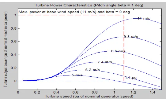
Thus, the wind power turbine characteristic is shown in figure 2.1.
In this paper, a wind turbine is simulated by using a look-up table, where inputs are wind speed and rotor speed and output is the mechanical torque.
III.
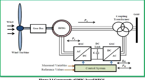
MODEL OF DOUBLY FED INDUCTION GENERATOR WIND TURBINEThe doubly-fed induction generator is widely used in wind power generation due to its high energy efficiency and controllability. This generator converts the wind energy into useful electrical power through wound rotor induction machine. As shown in figure 3.1, the DFIG-based WECS basically consists of a wound rotor induction machine, wind turbine with drive train system, rotor side converter (RSC), grid side converter (GSC), DC-link capacitor, and coupling transformer. The wound rotor induction machine stator winding is connected to the grid directly through a three-phase power transformer while the rotor winding is connected to the grid via AC/DC/AC IGBT power converter and a three-phase power transformer by slip rings and brushes, hence the term ‘doubly-fed’. The stator side of the DFIG is connected to the grid with fixed frequency ( fs ) and voltage, whereas the rotor side supplies a variable frequency which is controlled by the power converters before connecting to the grid. Because only part of the real power flows through the rotor circuit, these power converters are used to handle a fraction (25-30%) of the total power to accomplish independently full control of the real and the reactive power of generator. Thus, the losses in the power converters can be reduced because these converters handle less than 30% of the generator rated power. The control system controls the real and reactive power by changing the current flowing in the rotor winding to extract the maximum possible power from the wind. Therefore, the power of the rotor can be connected to the grid at the rated frequency by interposing the converters.
Figure 3.1 Components of DFIG-based WECS.
The active power of the stator is always flowing to the grid, independently of the operation state, whereas the machine operates as motor (sub-synchronism operation) when absorbing power, while the machine operates as a generator (hyper-synchronism or super synchronous operation) when supplying power. By neglecting the power losses, the relation between the rotor power (Pr ) and the stator power ( Ps ) through the slip ( S ) is given by:
where S is defined as the slip of the machine which is given by:
Therefore, the net power ( Pnet ) that is generated from both stator and rotor side can be expressed as :
Pnet = Ps + Pr = Ps – SPs = (1-S)Ps (3.2)
When the slip ( S ) is negative, the machine will operate in the hyper-synchronous (super synchronous) operation state (as a generator), while the machine will operate in the sub synchronous operation state (as a motor) when the slip ( S ) is positive, i.e. the rotor speed is slower than the synchronous speed. By this configuration, the wound rotor induction generator delivers directly the 2/3 of its rated power to the grid through the stator windings, while it delivers 1/3 of its rated power through the rotor windings via the converters.
IV. CONTROL MEACHNISM OF WIND TURBINE
In this scheme, each node with message searches for possible path nodes to copy its message. Hence, possible path The control system in the wind turbines plays an important role to control and extract the maximum energy from available wind while protecting the wind turbine components. Overall the power can be controlled by the following methods; the generator speed, blade angle adjustment, and yaw adjustment. The generator speed control is the most effective way to extract the maximum power from a low wind speed by using the power electronic converters as it will be discussed in the next section. For blade angle adjustment control, the pitch angle
adjustment is used to stall and furl the wind turbines as shown in figure 4.1 (A). By stalling a wind turbine, this will increase the angle of attack, which causes the flat side of the blade to face further into the wind. In contrast, Furling works by decreasing the angle of attack, causing the edge of the blade to face into the wind. Therefore, when fully furl turbine blades is made, this will stop the wind turbine completely. Pitch angle adjustment is a very effective way to limit output power by changing aerodynamic force on the blade at high wind speeds. For the yaw control, it is used to rotate the entire wind turbine to face the wind direction as shown in figure 4.1 (B).
A) Pitch adjustment (B) Yaw adjustment
In other words, the pitch angle control and controlling the synchronous speed of the generator are the most effective in the wind turbines control system as shown in figure 4.2, which is depicted a system-level layout of a wind energy conversion system.
Figure 4.2 System-level layout of a wind energy system.
V. RESULT AND DISCUSSION
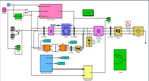
The proposed system having Wind turbines using a doubly-fed induction generator (DFIG) consist of a wound rotor induction generator and an AC/DC/AC IGBT-based PWM back to back converter. The stator winding is directly connected to the 50 Hz grid while the rotor is fed at variable frequency through the AC/DC/AC converter. Figure 5.1 shows the simulation model developed for the proposed work in MATLAB.
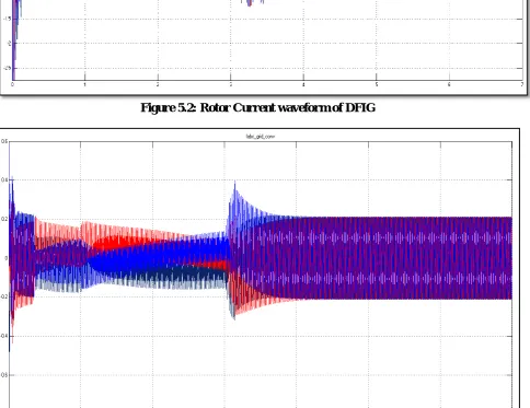
Figure 5.2: Rotor Current waveform of DFIG
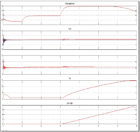
Figure 5.4: Waveform of (i) Rotor Speed (ii) Active and reactive power (iii) Electromagnetic torque (iv) DC voltage (v) Pitch angle.
VI. CONCLUSION
A detailed simulation model of a DFIG-based wind turbine system is developed for the wind turbine connected to the power grid. All of the primary components are modelled including the aerodynamic system of wind turbine, DFIG, rotor mechanical system, the overall control system, and the power grid. The stator side flux estimator is designed using a PLL system is embedded with the DFIG model which gives the reference angle to align the stator side voltage along the q-axis.
system equipped with a doubly-fed induction generator was developed in a Matlab/Simulink environment, which simulates the dynamics of the system from the turbine rotor, where the kinetic wind energy is converted to the mechanical energy, to the generator, which transforms the mechanical power to electrical power, and then to the grid connection point, where the electric power is fed into the grid. The model of the wind turbine system includes the aerodynamic models of the wind turbine, the drive train system models, the back-to-back converter models, and the doubly-fed induction generator models. Four control schemes were implemented in the wind turbine system, which are, the generator-side converter control, the grid-side converter control, the pitch angle control and the maximum power point tracking control, respectively.
The objective of the control scheme for the grid-side converter controller is used to maintain the constant voltage across the capacitor and produce a unity power factor operation of the grid. It also controls the pitch angle to maintain constant power. Hence the basic idea behind the proposed work is the control of pitch angle to maintain constant power across the lines. In last, the result of the test helps in determining the control of constant power output when the DFIG system equipped with the PI controller using pitch angle control method and also achieved maximum point power output. In the result section it has been shown that, the developed system can able to provide approximate constant power output at the steady state but also provides some oscillation in the power generated by DFIG during the wind speed variation.
REFERENCES
[1]. Mullane, G. Lightbody, R. Yacamini, “Adaptive control of variable speed wind turbines”, n proceedings of 36th Universities Power Engineering Conference, Swansea, 2001
[2]. Petersson, "Analysis, modeling and control of doubly-fed induction generators for wind turbines", Technical report no. 464L, School of Electrical Engineering, Chalmers University of Technology, Goteborg, Sweden, 2003
[3]. Yazdani, R. Iravani, “Voltage-Source Converters in Power Systems”, Wiley, IEEE press 2010 pp 25-150. applications,” IEEE Trans. Power Del., vol. 24, no. 4, pp. 2079-2089, 2009.
[4]. Chee-Mun Ong, Dynamic simulation of electric machinary using Matlab/Simulink, Prentice Hall, 1998
[5]. Dr. John Schonberger, Plexim Gmbh “Modeling a DFIG Wind Turbine System using PLECS” Technoparkstrasse Zurich, December 2008 pp. 2-3
[6]. Erich Hau, “Wind Turbines - Fundamentals, Technologies, Applications, Economics”, Springer Publishing, pp. 319-347, Second Edition, Year 2005.
[7]. Fthenakis, V. and Kim, H. C. (2009). "Land use and electricity generation: A lifecycle analysis". Renewable and Sustainable Energy Reviews 13 (6–7): 1465
[8]. J. Zhao, W. Zhang, Yikang He, J.HuI, “Modeling and control of a wind turbine- driven DFIG incorporating core saturation during grid voltage dips” International Conference on Electrical Machines and Systems (ICEMS 2008), pp. 2438 – 2442, 2008
[9]. M. Zhao, Z. Chen, F. Blaabjerg, “Load flow analysis for variable speed offshore Wind farms”, IET Renewable Power Generation, volume 3. Iss. 2, 2009, pp. 120-132.
[10]. S. Abourida, C. Dufour, J. Bélanger, V. Lapointe, “Real-Time, PC-Based Simulator of Electric Systems and Drives,” Proc. IPST, New Orleans, USA, 2003
BIOGRAPHY
Baljit Singh belongs to Allahabad, UP Received his Bachelor of Technology degree from Shree
Ganpati Institute of Technology, Ghaziabad. His working experience is at Medhaj Techno Concept