Low Complexity Linear Precoder Design For Mimo-Ofdm System
D. Swathi, Dr. K Amit Bindaj, Dr. J. Narendra Babu
P.G SCHOLAR, DEPT. of ECE, SAI TIRUMALA NVR ENGINEERING COLLEGE, JONNALAGADDA, GUNTUR PROFESSOR, DEPT. of ECE, SAI TIRUMALA NVR ENGINEERING COLLEGE, GUNTUR
, PROFESSOR & H.O.D, DEPT. of ECE, SAI TIRUMALA NVR ENGINEERING COLLEGE, GUNTUR
ABSTRACT: Orthogonal frequency division multiplexing (OFDM) is a well-known method for high data rate wireless transmission. OFDM may be combined with antenna arrays at the transmitter and receiver to increase the diversity gain and/or to enhance the system capacity on time-varying and frequency-selective channels, resulting in a multiple-input multiple-output (MIMO) configuration. This paper inspects different physical layer research challenges in MIMO-OFDM system design. It includes physical channel measurements and modeling, analog beam forming techniques using adaptive antenna arrays, space-time techniques for MIMO-OFDM, error control coding techniques, OFDM preamble and packet design, and signal processing algorithms used to perform time and frequency synchronization, channel estimation, and channel tracking in MIMO-OFDM systems. Finally, the paper examines a software radio implementation of MIMO-OFDM.
Keywords: Orthogonal frequency division multiplexing [OFDM], input multiple-output [MIMO].
I. INTRODUCTION
MIMO means multiple input, multiple
output. In 1998 Bell Laboratories
successfully revealed the MIMO system under laboratory conditions. In the following years Gigabit wireless Inc. and Stanford University developed a transmission scheme and jointly held the first prototype demonstration of MIMO. MIMO is an antenna technology.
This antenna technology includes multiple antennas which are used at both the source (transmitter) and the destination (receiver). The antennas at each end of the communications circuit are combined to minimize errors and optimize data speed. It is one of varied forms of smart antenna technology. The others being MISO (multiple input, single output) and SIMO (single input, multiple output). For example a 2*2 MIMO will have 2 antennas for transmitting signals (from base station) and 2 antennas to receive signals (mobile terminal).This is also known as downlink MIMO.
It is found that the signal can take many paths between a transmitter and a receiver. Moreover, by moving the antennas even a small distance the paths used will change. The diversity of paths available occurs as a result of the number of objects that appear to the side or even in the direct path between
the transmitter and receiver. These
additional paths can be used to advantage using MIMO. They can be used to give additional robustness to the radio link by improving the signal to noise ratio, or by increasing the link data capacity. The two main formats are:
Spatial multiplexing: This spatial
different paths to carry additional traffic, i.e. increasing the data throughput capability.
Spatial diversity: It is used in this narrower sense often mentioned to transmit and receive diversity. These two methodologies are utilized to give improvements in the signal to noise ratio and they are characterized by developing the reliability of the system with respect to the various forms of fading.
The wireless technology MIMO is able to significantly increase the capacity of a given channel while still obeying Shannon's law. It is possible to linearly increase in the throughput of the channel with every pair of antennas added to the system by increasing the number of receiving and transmitting antennas. This makes MIMO wireless technology one of the most significant wireless techniques to be employed in recent years. For the radio communications systems the spectral bandwidth becomes a
more precious commodity. Therefore,
techniques are needed for using the available bandwidth more efficiently. MIMO wireless technology is one of these techniques. Two important advantages of MIMO over SISO/ MISO are as given below:-
1. In MIMO, there is a significant increase in the capacity of the system and spectral efficiency. The capacity of a wireless link is increasing linearly with the minimum of the number of transmitter or receiver antennas. The data rate can be improved by spatial multiplexing without consuming more
resources of frequency and without
increasing the total transmit power.
2. In MIMO, due to the increased diversity there is a dramatic reduction of the effects of fading. This is particularly beneficial when the different channels fade independently.
II.UPLINK MIMO
Uplink MIMO schemes for LTE will vary from downlink MIMO schemes to which consider into account terminal complexity issues. MU-MIMO can be used for the uplink scheme. Multiple user terminals may transmit simultaneously on the same resource block. This is also referred as spatial domain multiple access (SDMA). The scheme needs only one transmit antenna at user equipment (UE) side which is a big advantage. The UEs sharing the same resource block have to utilize mutually orthogonal pilot patterns. To make use of the advantage of two or more transmit antennas but still keep the UE cost low, antenna subset selection can be used. In the starting, this technique will be used. For e.g. an UE will have two transmit antennas but only one transmits chain and amplifier. A switch will then choose the antenna that produces the best channel to transmit from user equipment to base terminal.
III. WORKING PRINCIPLE OF MIMO
Fig 1. Frame structure of MIMO TDS-OFDM.
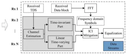
Fig 2. Receiver side of MIMO TDS-OFDM with ICI mitigation.
TDS-OFDM adopts known sequences as the guard interval, serving the purpose of both channel estimation and synchronization. MIMO TDS-OFDM utilizes pseudo-noise (PN) sequences as the guard interval. In
time-varying channels, the channel
estimation results from the PN sequences prior and posteriori to the OFDM data block which are kept to evaluate the channel variation model. In Fig. 1 and Fig. 2, the frame structure and receiver structure of MIMO TDS-OFDM using the proposed ICI mitigation algorithm are illustrated.
Frame structure of MIMO TDS-OFDM consists of transmitters from 1 to n and TDS, data block. These are transmitted to the Time varying MIMO channels. In Receiver structure of MIMO TDS-OFDM channel estimation is classified into time invariant part and linear time variant part. These are given to the ICI mitigation.
Received data is given to the FFT. Then this is performing operation of frequency domain symbols. Finally, the data is equalized.
All techniques assume that the multipath signal is harmful and attempt it to limit the harm. On the contrary MIMO takes advantage of multipath propagation (direct and reflected signals). MIMO uses multiple antennas to transmit multiple parallel signals. In an urban environment, signals will bounce off trees, high rise buildings and reach the receiver through different path. Receiver end uses an algorithm / DSP to sort out the multiple signals to produce one signal having originally transmitted data. Multiple data streams are transmitted in a single channel at the same time and at the receiver multiple radios collect the multipath signal. MIMO OFDM uses IFFT in the transmitter and FFT in the receiver. MIMO
can increase range, throughput and
reliability.
Orthogonal Frequency- Division
Multiplexing (OFDM) has appeared as a successful air-interface. The techniques of OFDM are also called as Discrete Multi-Tone (DMT) transmissions in the wired schemes and being utilized in Asymmetric Digital Subscriber Line (ADSL), High-bit-rate Digital Subscriber Line (HDSL), and Very-high-speed Digital Subscriber Line (VDSL).
Digital Video Broadcasting for Terrestrial
television (DVB-T), Digital Video
Broadcasting for Handheld terminals
(DVB-H), Wireless Local Area Networks
(WLANs) and Wireless Broadband Access Networks. Moreover, OFDM has been ratified as a standard by a number of standardization groups of the Institute of Electrical and Electronics Engineers (IEEE), such as the IEEE 802.11 and the IEEE 802.16 standard families.
There are many benefits in OFDM technique. They are Time-Division Multiple
Access (TDMA), Frequency-Division
Multiple Access (FDMA) and Code-Division Multiple Access (CDMA). The main benefit of OFDM is that the radio channel is divided into many narrow band,
low-rate, frequency-nonselective sub
channels or subcarriers. Hence, the multiple symbols can be transmitted in parallel, while maintaining a high spectral efficiency.
Each subcarrier may convey the information for a different user, which results in a simple
multiple-access scheme known as
Orthogonal Frequency-Division Multiple Access (OFDMA). This allows various media such as video, graphics, speech, text or other data to be transmitted within the same radio link, depends on the specific types of services and their Quality-of-Service (QOS) requirements.
Furthermore, in OFDM systems different modulation schemes can be employed for different subcarriers or even for different users. For example, the users which are close to the Base Station (BS) may have a
relatively good channel quality. Thus they can use high-order modulation schemes to increase their data rates. By contrast, for those users that are far from the BS or are serviced in highly loaded urban areas, where the subcarriers quality is expected to be poor, low-order modulation schemes can be invoked. OFDM uses IFFT in transmitter and FFT in receiver.
IV. PROPOSED MIMO – OFDM
The combination MIMO-OFDM is
advantageous. Hence, it simplifies
equalization dramatically in MIMO systems. Multiple-Input Multiple-Output (MIMO)
and Orthogonal Frequency-Division
Multiplexing (OFDM) technologies, indoor wireless systems could gain the data rates up to several hundreds of Mbits/s and achieve spectral efficiencies of several tens of bits/Hz/s, which are unattainable for
conventional single-input single-output
systems. The improvements of data rate and spectral efficiency which comes from the certainty that MIMO and OFDM methods
are certainly parallel transmission
Fig 3. System model of single user MIMO-OFDM system.
The MIMO-OFDM system performance is depends on the Fast Fourier Transform (FFT / IFFT) algorithm and MIMO encoding, such as Alamouti Space Time Block coding (STBC), the Vertical Bell-Labs layered Space Time Block code VBLASTSTBC, and Golden Space-Time Trellis Code (Golden STTC). OFDM has been acquired for various transmission systems. They are
Wireless Fidelity (WIFI), Worldwide
Interoperability for Microwave Access (WIMAX), Digital Video Broadcasting (DVB) and Long Term Evolution (LTE).
The OFDM system assigns subgroups of subcarriers to each user. With thousands of subcarriers, each user would obtain a small percentage of the carriers. In a modern system like the 4G LTE cellular system, each user could be allotted from one to many subcarriers. In LTE, subcarrier spacing is 15 kHz. Using a 10-MHz band, the total achievable number of subcarriers would be 666. In practice, a smaller number like 512 would be utilized. If each subscriber is considering six subcarriers, we can place 85 users in the band. The number
of subcarriers allotted will depends on the user’s bandwidth and speed needs.
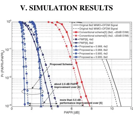
V. SIMULATION RESULTS
Fig 4. PAPR performance of the proposed scheme, conventional scheme and PMP.
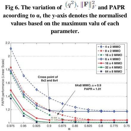
Fig 6. The variation of and PAPR acoording to α, the y-axis denotes the normalised
values based on the maximum valu of each parameter.
Fig 7.PAPR performance of the proposed scheme according to α with various MIMO
configurations.
VI. CONCLUSION
We have proposed a MIMO precoding scheme. It contains a sum of two matrices; one is made to MIMO precoding gain
associated with the cost factor α, the other of
which is designed to minimize PAPR by using redundant spatial dimensions at the
transmitter. When α is close to 1, we could
guarantee the effective data rate while
improving PAPR performance. It is
expected that a decision criterion of α can be
made by finding a connection point between our study and the related theoretical work which is left in the future work. Also, the joint consideration of the transmit and the receive PAPR is worthy of further study.
VII. REFERENCES
[1] H. Ochiai and H. Imai, “Performance analysis of deliberately clipped OFDM signals,”
IEEE Trans. Commun., vol. 50, no. 1, pp. 89– 101, Jan. 2002.
[2] J. Armstrong, “Peak-to-average power reduction for OFDM by repeated clipping and
frequency domain filtering,” Electron. Lett., vol.
38, no. 5, pp. 246–247, Feb. 2002.
[3] Y. C. Wang and Z. Q. Luo, “Optimized iterative clipping and filtering for PAPR
reduction of OFDM signals,” IEEE Trans.
Commun., vol. 59, no. 1, pp. 33–37, Jan. 2011. [4] A. Aggarwal and T. H. Meng, “Minimizing the peak-to-average power ratio of OFDM
signals using convex optimization,” IEEE Trans.
Signal Process., vol. 54, no. 8, pp. 3099–3110, Aug. 2006.
[5] A. Aggarwal, E. Stauffer, and T. Meng, “Optimal peak-to-average power ratio reduction
inMIMO-OFDM systems,” in Proc. IEEE ICC,
Jun. 2006, pp. 3094–3099.
[6] C. Studer and E. G. Larsson, “PAR-aware
large-scale multi-user MIMO-OFDM
downlink,” IEEE J. Sel. Areas Commun., vol.
31, no. 2, pp. 303–313, Feb. 2013.
[7] D. J. Love and R. W. Heath, “Multimode
precoding for MIMO wireless systems,” IEEE
Trans. Signal Process., vol. 53, no. 10, pp. 3674–3687, Oct. 2005.
[8] A. Wiesel, Y. C. Eldar, and S. Shamai,
“Zero-forcing precoding and generalized
inverses,” IEEE Trans. Signal Process., vol. 56,
no. 9, pp. 4409–4418, Sep. 2008.
[9] M. Grant and S. Boyd, CVX: Matlab Software for Disciplined Convex Programming, version 2.1, Mar. 2014.
[10] S. J. Wright, Primal-Dual Interior-Point