ISSN 2348 – 7968
An Overview of Virtual Router Redundancy Protocol Techniques and
Implementation for Enterprise Networks
Dr. P. Rajamohan
Senior Lecturer, School of Information Technology, SEGi University Kota Damansara, PJU 5, 47810 PJ, Selangor, Malaysia
Abstract
The needs of network in most of the enterprise companies/campus as increase day by day depends on the demands of resources sharing. In order to have smooth and suitable as well as good availability of networks resources 24/7. In VRRP there are a three advantages that are found, first is one is high availability, load balancing and business continuity. VRRP is a popular protocol for providing device redundancy, for connecting redundant WAN gateway routers or server access switches. It allows a backup router or switch to automatically take over if the primary (master) router or switch fails. This paper presents the VRRP techniques, performance, advantages and implementation approach by the way of how the VRRP uses dynamic failover to ensure the availability of an end node’s default router.
.
Keywords: VRRP- Virtual Routing Redundancy Protocol, VLAN- Virtual Local Area Network, VR- Virtual Router, VRID- Virtual Router Identification, MAC - Media Access Control.
1. INTRODUCTION
In many networks, edge devices are often configured to send packets to a statically configured default router. If this router becomes unavailable, the devices that use it as their first-hop router become isolated from the network. VRRP is a popular protocol for providing device redundancy, for connecting redundant WAN gateway routers or server access switches. It allows a backup router or switch to automatically take over if the primary (master) router or switch fails.
VRRP works by grouping the redundant routers together into a single virtual router. That virtual router entity has an IP address of its own. Instead of sending traffic to an individual router, PCs etc send traffic to the virtual router address (for example, by using the virtual router address as their gateway address). The master router processes traffic that is addressed to the virtual router address and forwards it appropriately. The master router also sends out regular advertisements to the backup router. If the master router goes down, the backup router stops receiving these advertisements. In that case, the backup router takes over as the master router and starts processing
traffic. When the original master router comes back up, it takes over as the master router again[1]-[3].
VRRP uses dynamic failover to ensure the availability of an end node’s default router. This is done by assigning the IP address used as the default route to a “Virtual Router”, or VR. The VR includes:
• An Owner router assigned to forward traffic designated for the virtual router (If the Owner is forwarding traffic for the VR, it is the Master
router for that VR.)
• One or more prioritized Backup routers (If a Backup is forwarding traffic for the VR, it has replaced the Owner as the Master router for that VR.)
This redundancy provides a backup for gateway IP addresses (first- hop routers) so that if a VR’s Master router becomes unavailable, the traffic it supports will be transferred to a Backup router without major delays or operator intervention. This operation can eliminate single-point-of-failure problems and provide dynamic failover (and failback) support. As long as one physical router in a VR configuration is available, the IP addresses assigned to the VR are always available, and the edge devices can send packets to these IP addresses without interruption[1]-[4].
1.1 Advantages of using VRRP
• Minimizing failover time and bandwidth overhead if a primary router becomes unavailable
• Mminimizing service disruptions during a failover • Providing backup for a load-balanced routing
solution
• Addressing failover problems at the router level instead of on the network edge
• Avoiding the need to make configuration changes in the end nodes if a gateway router fails
• Eliminating the need for router discovery
ISSN 2348 – 7968
1.2 Backup
A router configured in a VR as a Backup to the Owner configured for the same VR. There must be a minimum of one Backup in a VR to support VRRP operation if the Owner fails. Every backup is created with a configurable priority (default: 100) that determines the precedence for becoming the Master of the VR if the Owner or another Backup operating as the Master becomes unavailable.
1.3 Master
The Owner or Backup router that is currently the physical forwarding agent for routed traffic using the VR as a gateway. There can be only one router operating as the Master for a network or (in the case of a multinetted VLAN) a subnet. If the router configured as the Owner for a VR is available to the network, it will also be the Master. If the Owner fails or loses availability to the network, the highest-priority Backup becomes the Master.
1.4 Owner
The router configured in a VR to “own” the “virtual” IP address associated with the VR.(The virtual IP address for the VR must be configured as a real IP address on the VLAN on which the VR is configured. The Owner is automatically configured with the highest VRRP router priority in the VR (255) and operates as the Master router for the VR unless it becomes unavailable to the network.
1.5 VR (Virtual Router)
Consists of one Owner router and one or more Backup routers, all of which belong to the same network or (in the case of a multinetted VLAN, the same subnet). The Owner is the router that owns the IP address(es) associated with the VR. The VR has one virtual IP address (or, in the case of a multinetted VLAN, multiple, virtual IP addresses) that corresponds to a real IP address on the Owner, and is assigned an identification number termed the VRID.
1.6 VRID
The identifier for a specific VR configured on a specific VLAN interface. On a given router, a VRID can be used for only one VR in a given VLAN, but can be used again for a different VR in a different VLAN.
This paper presents about the performances of VRRP techniques and efficient way of installation through
using of multiple gateway so as avoid single point failure and make the availability of network to be constant[2]-[6].
2. VRRP TECHNIQUES AND GENERAL
OPERATION
VRRP supports router redundancy through a prioritized election process among routers configured as members of the same virtual router (VR). On a given VLAN, a VR includes two or more member routers configured with a virtual IP address that is also configured as a real IP address on one of the routers, plus a virtual router MAC address. The router that owns the IP address is configured to operate as the Owner of the VR for traffic-forwarding purposes, and by default has the highest VRRP priority in the VR. The other router(s) in the VR have a lower priority and are configured to operate as Backups in case the Owner router becomes unavailable[2][3][8]-[10].
The Owner normally operates as the Master for a VR. But if it becomes unavailable, then a failover to a Backup router belonging to the same VR occurs, and this Backup becomes the current Master. If the Owner recovers, a failback occurs, and “Master” status reverts to the Owner. (Note that using more than one Backup provides additional redundancy, meaning that if both the Owner and the highest-priority Backup fail, then another, lower-priority Backup can take over as Master.) 3][8]-[10].
• The virtual IP address used by all VRRP routers in a VR instance is a real IP address that is also configured on the applicable VLAN interface on the VR’s Owner router.
• The same MAC and virtual IP addresses are
included in the VRRP configuration for the Owner and all Backup routers belonging to the same VR, and are used as the source addresses for all traffic forwarded by the VR.
2.1 Virtual Router (VR)
A Virtual Router (VR) instance consists of one Owner router and one or more Backup routers belonging to the same network. Any VR instance exists within a specific VLAN, and all members of a given VR must belong to the same subnet. In a multinetted VLAN, multiple VRs can be configured. The Owner operates as the VR’s Master unless it becomes unavailable, in which case the highest-priority backup becomes the VR’s Master.
ISSN 2348 – 7968 • A virtual router identification (VRID) configured
on all VRRP routers in the same network or, in the case of a multinetted VLAN, on all routers in the same subnet.
• The same virtual IP address configured on each instance of the same VR.
• A status of either Owner or Backup configured on each instance of the same VR (On a given VR there can be one Owner and One or more Backups.)
• A priority level configured on each instance of the VR (On the Owner router the highest priority setting, 255, is automatically fixed. On Backups, the default priority setting is 100 and is
configurable.)
• A VR MAC address (not configurable)
Where a VLAN is configured with only one network (IP address), one VR is allowed in that VLAN. In a multinetted VLAN, there can be one VR per subnet, with a maximum of 32 VRs in any combination of Masters and Backups.[3][9]
2.2 Virtual IP Address
The virtual IP address associated with a VR must be a real IP address already configured in the associated VLAN interface on the Owner router in the VR. Also, the Owner and all other (Backup) routers belonging to the VR have this IP address configured in their VRID contexts as the virtual IP address. If the configured Owner in a VR becomes unavailable, then it is no longer the Master for the VR and a Backup router in the VR is elected to assume the role of Master, as described under “Backup Router”.
A subnetted VLAN allows multiple, virtual IP addresses. However, if there are 32 or fewer IP addresses in a VLAN interface and you want VRRP support on multiple subnets, then the recommended approach is to configure a separate VR instance for each IP address in the VLAN. In cases where VRRP support is needed for more than 32 IP addresses in the same VLAN, refer to “Associating More Than One Virtual IP Address With a VR”. [3][10]
2.3 Master Router
The current Master router in a VR operates as the “real”, or physical gateway router for the network or subnet for which a virtual IP address is configured .
2.3.1 Control of Master Selection.
Selection of the Master is controlled by the VRRP priority value configured in the VRID context of each router in the VR. The router configured as the Owner in the VR is automatically assigned the highest VRRP priority (255) and, as long as it remains available, operates as the Master router for the VR. (The other routers belonging to the VR as Backups are assigned the default priority value (100) and can be reconfigured to any priority value between 1 and 254, inclusive.) If the current Master becomes unavailable, the protocol uses the priority values configured on the other, available routers in the VR to select another router in the VR to take over the Master function.[3]
2.3.2 Function of the VRRP Advertisement.
The current Master router sends periodic advertisements to inform the other router(s) in the VR of its operational status. If the backup VR(s) fail to receive a Master advertisement within the timeout interval, the current Master is assumed to be unavailable and a new Master is elected from the existing Backups. The timeout interval for a VR is three times the advertisement interval configured on the VR(s) in the network or subnet. In the default VRRP configuration, the advertisement interval is one second and the resulting timeout interval is three seconds.[3][5]-[7]
2.4 Owner Router
An Owner router for a VR is the default Master router for the VR, and operates as the Owner for all subnets included in the VR. As mentioned earlier, the VRRP priority on an Owner router is always 255 (the highest). On a multinetted VLAN where multiple subnets are configured in the same VR, the router must be either the Owner for all subnets in the VR or a Backup for all subnets in the VR.[2][3]
2.5 Backup Router
There must be at least one Backup router. A given VR instance on a Backup router must be configured with the same virtual IP address as the Owner for that VR (and both routers must belong to the same network or subnet)[3]
2.5.1 VR Priority Operation.
ISSN 2348 – 7968
in which Backups will be reassigned as Master in the event of a failover from the Owner.[3]-[7]
2.5.2 Preempt Mode.
Where multiple Backup routers exist in a VR, if the current Master fails and the highest-priority Backup is not available, then VRRP selects the next-highest priority Backup to operate as Master. If the highest-priority Backup later becomes available, it pre-empts the lower-priority Backup and takes over the Master function. If you don’t want a Backup router to have this preemptive ability on a particular VR, you can disable this operation with the
no preempt-mode command.[3] (Note that Preempt Mode applies only to VRRP routers configured as Backups.)
2.6 Virtual Router MAC Address
When a VR instance is configured, the protocol automatically assigns a MAC address based on the standard MAC prefix for VRRP packets, plus the VRID number (as described in RFC 3768). The first five octets form the standard MAC prefix for VRRP, and the last octet is the configured VRID. That is:[2][3]
00-00-5E-00-01-< VRid >
For example, the virtual router MAC address for the VR in is 00-00-5E-00-01-01.
2.7 General Operating Rules
• IP routing must be enabled on the router before enabling VRRP.
• IP must be enabled on a VLAN before creating a VR instance on the VLAN.
• Virtual IP address:
• On an Owner: The virtual IP address configured in a VR instance must match one of the IP addresses configured in the VLAN interface on which the VR is configured.
• On a Backup: The virtual IP address configured in a VR instance cannot be a “real” IP address configured in a VLAN interface on that router. • Before changing a router from Owner to Backup,
or the reverse, the virtual IP address must be removed from the configuration.
• The priority configuration on an Owner can only be 255. The priority configuration on a Backup must be 254 or lower; the default being 100. • Advertisement intervals:
• A VRRP router must be configured as an Owner or Backup before configuring the advertisement interval.
• If a VRRP router has a different advertisement interval than a VRRP packet it receives, the router drops the packet. For this reason, the advertisement interval must be the same for the Owner and all Backups in the same VR.
• When a VR is active you cannot change any of the following on that VR:
• priority
• advertisement interval • preempt mode • virtual IP address
• A VR exists within a single VLAN interface. If the VLAN is multinetted, then a separate VR can be configured within the VLAN for each subnet. A VLAN allows up to 32 VRs and the switch allows up to 2048 VRs.
• All routers in the same VR must belong to the same network or subnet.
• The router supports the following maximums: • 32 VRs per VLAN in any combination of Masters and Backups
• 2048 VRs per router • 32 IP addresses per VR
• Each VR uses one MAC address as described
under “Virtual Router MAC Address”.
• If an IP address is deleted on a VLAN interface, one of the following occurs:
• VR Owner: If the VR uses the same IP address as a virtual IP address, then that IP address is deleted from the VR.
• VR Backup: If the VR has a virtual IP address in the same subnet as that of the deleted IP address, then that virtual IP address will be deleted from the VR.[2][4]-[7][10]
If the deleted virtual IP address was the last virtual IP address of an active VR, then the VR will be deactivated.
2.8 Steps for Provisioning VRRP Operation
2.8.1 Basic Configuration Process
This process assumes the following for VRRP operation:
• VLANs on the selected routers are already configured and IP-enabled.
• IP routing is enabled
ISSN 2348 – 7968
2.8.2. Configure the Owner for VRRP operation and a VR instance.
a. On the router intended as the Owner for a particular network or subnet, enter the global configuration context and enable VRRP.
router vrrp
b. Enter the desired VLAN context and configure a VR instance.
vlan < vid >
vrrp vrid < 1 - 255 >
Note that this step places the CLI in the context of the specified VR.
c. Configure the router as the Owner of the VR instance.
owner
Note that this step automatically fixes the router’s priority as 255 (the highest) for this VR instance. (The Owner priority cannot change.)
d. Configure the router’s real IP address and subnet mask for the current VLAN interface as the virtual IP address for the VR instance. You can use either of the following methods:
virtual-ip-address < ip-mask > virtual-ip-address/mask-bits
e. Activate the Owner VR instance.
enable
f. Inspect the configuration for the Owner VR.
show vrrp vlan < vid > vrid < vrid-# > config
Leave the Owner’s advertisement interval at its default (1 second). [2]-[5][10]
2.8.3 Configure a Backup for the same VR instance as for the Owner in step 2.8.2.
a. On another router with an interface in the same network or subnet as is the Owner (configured in step 2.8.2), enter the global configuration context and enable VRRP.
router vrrp
b. Configure (and enter) the same VR instance as was configured for the Owner in step 2.8.2.
vlan < vid >
vrrp vrid < 1 - 255 >
c. Configure the router as a Backup for the VR instance.
backup
Note that this step sets the Backup router’s priority as 100 for this VR instance.
d. Optional: If there is only one Backup router, or if you want the priority among backups to be determined by the lowest IP address among the Backups, leave the VR instance priority for the current backup router at the default of 100. If you want to control Backup router priority by creating a numeric hierarchy among the Backup routers in the VR, then set the priority on each accordingly.
priority < 1 - 254 >
e. Configure the virtual IP address for the current VR. Use the same address as you used for the Owner router’s instance of the VR. As mentioned earlier, you can use either of the following methods:
virtual-ip-address < ip-mask > virtual-ip-address/mask-bits
f. Activate the Backup VR instance.
enable
g. Inspect the configuration for the Owner VR.
show vrrp vlan < vid > vrid < vrid-# > config
Leave the advertisement interval for Backup routers at the default (1second). [2]-[5][10]
2.8.4. Repeat step 2.8.3 for each Backup router on the same VR. [2]-[5][10]
3. VRRP IMPLEMENTATION METHODS
AND SOLUTION
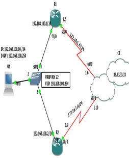
We are configure R1 and R2 are connected in the same LAN. We are going to configure HSRP for that case we will create a virtual router help of a virtual- IP. This Virtual IP used as the default-gateway of the all devices of the LAN. Using Cisco Packet Tracer Simulation software the following task has been done to show VRRP operations.[2]-[3][10]
Task 1: Configure R4 must be work as a host.
Task 2: Configure R3 with routing protocol Static Route.
Task 3: Configure R1 and R2 with static route & virtual IP 192.168.100.254 with standby group 22
ISSN 2348 – 7968
Task 1: Configure R4 must be work as a host.
Here we will make this router will work as a host Figure 1: VRRP Implementation Design Topology
3.1 Task 1: Configure R4 must be Work as a Host
R4 works as a PC/Host configuration
R4#configure terminal R4(config)#hostname PC10 PC10(config)#no ip routing PC10(config)#
PC10(config)#ip default-gateway 192.168.100.254 // Virtual IP Address
PC10(config)#interface fastEthernet 0/0
PC10(config-if)#ip address 192.168.100.10 255.255.255.0 PC10(config-if)#no shutdown
PC10(config-if)#exit
PC10(config)#do show ip interface brief
Interface IP-Address OK? Method Status Protocol FastEthernet0/0 192.168.100.10 YES NVRAM up up
PC10(config)#do write
Warning: Attempting to overwrite an NVRAM configuration previously written
by a different version of the system image.
Overwrite the previous NVRAM configuration?[confirm] Building configuration...
[OK]
PC10(config)#
Now R4 works as a PC/Host.
3.2 Task 2: Configure R3 with Static Route
R3 configuration
R3#configure terminal
Enter configuration commands, one per line. End with CNTL/Z.
R3(config)#interface loopback 0
R3(config-if)#ip address 33.33.33.33 255.255.255.255 R3(config-if)#no sh
R3(config-if)#exit R3(config)#
R3(config)#interface Serial0/0
R3(config-if)# description << Connected to the R- 1 >> R3(config-if)# ip address 172.16.1.6 255.255.255.252 R3(config-if)# clockrate 128000
R3(config-if)#exit R3(config)#
R3(config)#interface Serial0/1
R3(config-if)# description << Connected to the R- 2 >> R3(config-if)# ip address 172.16.1.10 255.255.255.252 R3(config-if)# clockrate 128000
R3(config-if)#exit R3(config)#
R3(config)# ip route 192.168.100.0 255.255.255.0 Serial0/0
R3(config)# ip route 192.168.100.0 255.255.255.0 Serial0/1
R3(config-router)#end
R3#copy running-config startup-config Destination filename [startup-config]? Warning: Attempting to overwrite an NVRAM configuration previously written
by a different version of the system image.
Overwrite the previous NVRAM configuration?[confirm] Building configuration...
[OK]
R3#
R3#show ip interface brief
ISSN 2348 – 7968
Serial0/1 172.16.1.10 YES NVRAM up up
Serial0/2 unassigned YES NVRAM administratively down down
Serial0/3 unassigned YES NVRAM administratively down down
Ethernet1/0 unassignedYES NVRAM administratively down down
Ethernet1/1 unassigned YES NVRAM administratively down down
Ethernet1/2 unassigned YES NVRAM administratively down down
Ethernet1/3 unassigned YES NVRAM administratively down down
FastEthernet2/0 unassigned YES NVRAM administratively down down
Loopback 0 33.33.33.33 YES NVRAM up up
3.3 Task 3: Configure R1 and R2 with Static
Route and Virtual IP 192.168.100.254
with
Standby Group 22
R1 Configuration
R1#configure terminal
Enter configuration commands, one per line. End with CNTL/Z.
R1(config)#interface serial 0/0
R1(config-if)#description <<Connected to the R-3>> R1(config-if)#ip address 172.16.1.5 255.255.255.252 R1(config-if)#clockrate 128000
R1(config-if)#no shutdown R1(config-if)# exit
R1(config)#interface FastEthernet1/0
R1(config-if)#ip address 192.168.100.1 255.255.255.0 R1(config-if)#no shutdown
R1(config-if)# vrrp 22 ip 192.168.100.254 // Group Number
R1(config-if)#vrrp 22 timers advertise 5 //Set the advertisement timers
R1(config-if)#exit
R1(config)# ip route 33.33.33.33 255.255.255.255 Serial0/0
R1(config-router)#end
R1#write
Warning: Attempting to overwrite an NVRAM configuration previously written
by a different version of the system image.
Overwrite the previous NVRAM configuration?[confirm] Building configuration...
[OK]
R2 Configuration
R2#configure terminal
Enter configuration commands, one per line. End with CNTL/Z.
R2(config)#interface serial 0/0
R2(config-if)#description <<Connected to the R-3>> R2(config-if)#ip address 172.16.1.9 255.255.255.252 R2(config-if)#clockrate 128000
R2(config-if)#no shutdown R2(config-if)# exit
R2(config)#interface FastEthernet1/0
R2(config-if)#ip address 192.168.100.2 255.255.255.0 R2(config-if)#no shutdown
R2(config-if)#vrrp 22 ip 192.168.100.254 // Group Number
R2(config-if)#vrrp 22 timer learn // Learn timer values from current Master.
R2(config-if)#exit
R2(config)# ip route 33.33.33.33 255.255.255.255 Serial0/0
R2(config-router)#end
R2#write
Warning: Attempting to overwrite an NVRAM configuration previously written
by a different version of the system image.
Overwrite the previous NVRAM configuration?[confirm] Building configuration...
[OK]
---
Here in VRRP Preemption is automatic enable. ---
3.4 Task 3: Verify Using Show command and
Trace Route
R4#ping 33.33.33.33
Type escape sequence to abort.
Sending 5, 100-byte ICMP Echos to 33.33.33.33, timeout is 2 seconds: !!!!!
Success rate is 100 percent (5/5), round-trip min/avg/max = 16/47/64 ms
R4#traceroute 33.33.33.33 Type escape sequence to abort. Tracing the route to 33.33.33.33
ISSN 2348 – 7968
Note: PC50 ping in the R-3 Loopback 33.33.33.33 packets are go via R-2 because R2 is Master here Now we shutdown the R-2 interface let see what will happen
Here we try to ping in the repeat at the same time we go to R2 fa1/0 and shutdown
R4#ping 33.33.33.33 repeat 666
Type escape sequence to abort.
Sending 666, 100-byte ICMP Echos to 33.33.33.33, timeout is 2 seconds:
!!!!!!!!!!!!!!!!!!!!!!!!!!!!!!!!!!!!!!!!!!!!!!!!!!!!!!!!!!!!!!!!!!!!!! Success rate is 99 percent (665/666), round-trip
min/avg/max = 8/47/136 ms R4#
--- R2(config)#int fa1/0
R2(config-if)#shutdown R2(config-if)#
*Mar 1 00:22:16.039: %VRRP-6-STATECHANGE: Fa1/0 Grp 22 state Master -> Init
R2(config-if)#
*Mar 1 00:22:18.039: %LINK-5-CHANGED: Interface FastEthernet1/0, changed state to administratively down *Mar 1 00:22:19.039: %LINEPROTO-5-UPDOWN: Line protocol on Interface FastEthernet1/0, changed state to down
R2(config-if)#
=========================================
Fantastic no any packet is not drop !!! Due to VRRP. ========================================= R1#show vrrp
FastEthernet1/0 - Group 22 State is Master
Virtual IP address is 192.168.100.254 Virtual MAC address is 0000.5e00.0116 Advertisement interval is 1.000 sec Preemption enabled
Priority is 100
Master Router is 192.168.100.1 (local), priority is 100 Master Advertisement interval is 1.000 sec
Master Down interval is 3.609 sec
R2#
R2#show vrrp
FastEthernet1/0 - Group 22 State is Init
Virtual IP address is 192.168.100.254 Virtual MAC address is 0000.5e00.0116 Advertisement interval is 1.000 sec Preemption enabled
Priority is 100
Master Router is unknown, priority is unknown Master Advertisement interval is unknown Master Down interval is unknown
--- When R-2 fa1/0 interface will comes up the R1 VRRS becomes Master
--- R2(config)#int fa1/0
R2(config-if)#no shutdown R2(config-if)#end
R2# R2# R2#write
Building configuration...
R2#show vrrp
FastEthernet1/0 - Group 22 State is Backup
Virtual IP address is 192.168.100.254 Virtual MAC address is 0000.5e00.0116 Advertisement interval is 1.000 sec Preemption enabled
Priority is 100
Master Router is 192.168.100.1, priority is 100 Master Advertisement interval is 1.000 sec
Master Down interval is 3.609 sec (expires in 2.745 sec)
R2#
R1#show vrrp
FastEthernet1/0 - Group 22 State is Master
Virtual IP address is 192.168.100.254 Virtual MAC address is 0000.5e00.0116 Advertisement interval is 1.000 sec Preemption enabled
Priority is 100
Master Router is 192.168.100.1 (local), priority is 100 Master Advertisement interval is 1.000 sec
Master Down interval is 3.609 sec PC50#traceroute 33.33.33.33
Type escape sequence to abort. Tracing the route to 33.33.33.33
1 192.168.100.1 124 msec 68 msec 80 msec 2 172.16.1.6 140 msec * 44 msec
PC50# PC50#
ISSN 2348 – 7968
4. CONCLUSION
VRRP promises enterprises networks with high level of services availability even any one networks router failure in that networks topology. VRRP works by grouping the redundant routers together into a single virtual router. That virtual router entity has an IP address of its own. Instead of sending traffic to an individual router, PCs etc send traffic to the virtual router address (for example, by using the virtual router address as their gateway address). The master router processes traffic that is addressed to the virtual router address and forwards it appropriately. The master router also sends out regular advertisements to the backup router. If the master router goes down, the backup router stops receiving these advertisements. In that case, the backup router takes over as the master router and starts processing traffic. When the original master router comes back up, it takes over as the master router again. From this fact VRRP is the best protocol to be applied to a enterprise networks environment hence provide load balancing, business continuity and redundancy network all the time.
5. REFERENCES
[1] Srivastava, A. (2009). Virtual Routing Redundacy Protocol. [e-book] Tech Mahindra,.Techmahindra.com, Chapter -VRRP [2] Cisco Press, Virtual Router Redundancy Protocol (VRRP), www.ciscopress.com, Chapter 6.1 - 6.35.
[3] Cisco press, Network Sales and Services Handbook ( Cisco Press Networking Technology - Chapter VRRP
[4] Controleng.com,(2011), Network redundancy reduces risk, downtime | Control Engineering. Article : Network Redundancy [5] Lluis, . et al. (2013). In-Network Redundancy Generation for Opportunistic Speedup of Backup.Future Generation Computer Systems, 29 (6), pp.1353-1362
[6] Nychis,et. al,(2012, August). On-chip networks from a networking perspective: Congestion and scalability in many-core interconnects.
[7] Radware.com (2013). An Introduction to Load Balancing Applications.[online] Resources -load balancing introduction. [8] Syme, M. and Goldie, P. (2004). Optimizing Network Performance with Content Switching: Server, Firewall, and Cache Load Balancing. paper Saddle River: Prentice Hall Professiona. pp.262
[9] Miki, T. and Hayasaka, M. (2013) A Network Architecture with High Availability for Real-time Premium Traffic over the Internet. Journal of Network and Systems Management, 16 ( 2), pp. 201 - 221.
[10] AlliedWare™ OS How To Note, www.alliedtelesis.com: How to VRRP Configure VRRP (Virtual Router Redundancy Protocol) pp:1-7.
Author