High Speed 128-bit BCD Adder Architecture
Using CLA
J.S.V.Sai Prasanthi 1, Y.Yamini Devi2
PG Student [VLSI&ES], Dept. of ECE, Swamy Vivekananda Engineering College, Kalavarai, Andhrapradesh, India1 Assistant Professor, Dept. of ECE, Swamy Vivekanada Engineering College, Kalavarai, Andhrapradesh, India2
ABSTRACT: Arithmetic and memory address computation are performed using adder operations. Hence, design of adders forms an important subset of electronic chip design functionality. BCD numbers play a prominent role in number system. To perform arithmetic operations on BCD numbers respective circuit has to be designed. To perform BCD addition, BCD adders are used. But the drawback with the BCD adder is low speed in operation due to delay in propagating carry output. This low speed operation will affect the operation of entire system in which it is used. As the technology is advancing day by day there is demand for chips with high speed. So to overcome this drawback, BCD adder using CLA is proposed in this paper. The proposed design is attempted here to reduce the delay and thereby increasing the speed of response. In existing BCD architecture, RCA is used to add numbers. The delay of RCA is high so it is effecting the speed of adder. So in the proposed design, CLA is used instead of RCA and also a parallel prefix network is to be used to produce the carry outputs for all stages. In this paper, a BCD adder using CLA is to be designed for 8, 16, 32, 64 and 128-bit size using VHDL with the help of ISE Xilinx design suite 14.1. The designed adder will be functionally verified by using ISIM simulator. Later, it will be synthesized using XST synthesizer to get the area (in terms of LUTS) and delay(ns). Finally, the designed BCD adders will be compared with conventional BCD adder in terms of delay(ns).
KEYWORDS: BCD Adder, RCA, CLA, parallel prefix network, ISE Xilinx design suite14.1, ISIM simulator, XST synthesizer
I.INTRODUCTION
Human beings have preferred decimal as their number base for all calculations done by hand, since the time when the man learned to count on his ten fingers. This fact has never changed, although binary has been selected as the default base for almost all computers due to the storage and the speed efficiency of binary hardware. The success of binary numbers was introduced in 1946, by the report of John von Neumann and his colleagues at the Institute for Advanced Study [1]. Afterwards, the designers have preferred binary computers due to the speed and the simplicity of binary arithmetic, but nowadays, there is an increasing demand for the decimal arithmetic hardware support in financial and commercial applications.
In all arithmetic units, whether binary or decimal, an adder is used [2]. Therefore, it is not surprising that various addition techniques have been invented up to now, even for the decimal addition, which is much less popular than the binary addition BCD is very common in electronic system where a numeric value is to be displayed, especially in systems consisting solely of digital logic, and not containing a microprocessor.
Enter inputs A, B, Cin
Start
Convert A, B into binary
Numbers
BCD Addition
Add correction
Factor 0 or 6
Result
Sum>9
NO
YES
This paper is structured in brief as Follows-Section II explains about the BCD addition algorithm and Section III describes the structure and working of conventional BCD adder (nothing but present existing BCD adder). Section IV discusses about the proposed BCD adder structure by using CLA. The results are explained in section V Finally, the paper ends with conclusion and future scope.
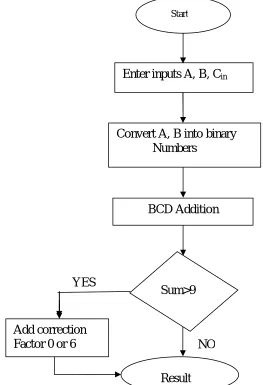
II.BCD ADDITION ALGORITHM
BCD or Binary Coded Decimal is the number system which has the binary numbers or digits to represent decimal number. A decimal number contains 10 digits (0-9). Now the equivalent binary numbers can be found out of these 10 decimal numbers. Like other number systems BCD operation may be required. BCD is a numerical code which has several rules for addition [6]. The rules are given below in three steps.
Fig. 1 Flowchart for BCD addition algorithm
If the sum of the two digits is smaller than 9 there is no carry even though there is a carry
SUM A
B
Cin
Carry
If the sum of the two digits is exactly 9 the input carry determines whether a correction is required and a carry Output is produced. Figure 1 represents the algorithm for BCD addition.
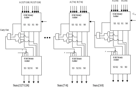
III.CONVENTIONAL BCD ARCHITECTURE
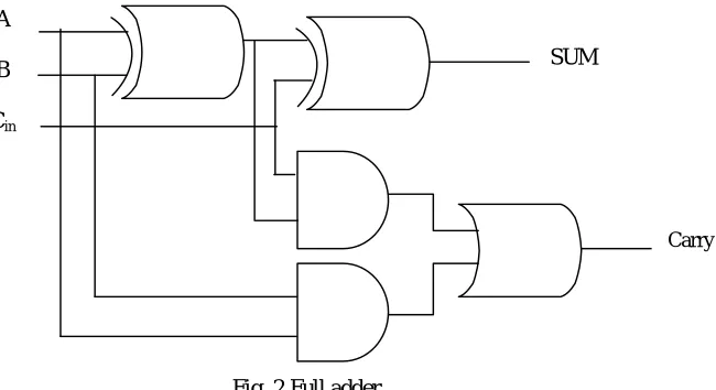
Figure 3 shows a conventional BCD adder consists of bit binary adder and carry out circuit. The top module of the 4-bit binary adder act as the ripple carry adder .it consists of series of full adder. The middle module of the carryout circuit consists of OR gate and 2 AND gates. The bottom module of the 4-bit binary adder act as ripple carry adder. Ripple Carry adder consist of series of one half adder and number of full adders. The carryout of one stage is fed directly to the carry-in of the next stage. Cout is used for the correction factor. The first four level BCD adders produce the binary addition. If the result is greater than ‘9’ a carry output is produced. The result of first level 4-bit adder is corrected by adding ‘6’ and also this carry output is used as carry input for the next digit. The 1-bit full adder is the building block of all the modules. The output of full adder is sum and carry output. The binary adder is made up from standard AND and OR gates and allow us to add together single bit binary numbers A and B produce the outputs the sum of the addition and a carry called the carry out (c out bit). The full adder gate level circuit is as shown in fig .3. The first four level BCD adders produce the binary addition. If the result is greater than ‘9’ a carry output is produced. The result of first level 4-bit adder is corrected by adding ‘6’ and also this carry output is used as carry input for the next digit.
Fig. 2 Full adder
The Boolean expression for S and Co is given As
i
C
B
A
S
=
A
B
C
i
A
B
C
i
A
B
C
i
ABC
iCo= AB + BC i + AC i
The 1-bit full adder is the building block of all the modules. The output of full adder is sum and carry output. The binary adder is made up from standard AND and OR gates and allow us to add together single bit binary numbers A and B produce the outputs the sum of the addition and a carry called the carry out (cout bit). Figure 2 shows the full
adder gate level circuit.The third level of CBCD architecture consists of a RCA. This RCA is used to correct the sum output by adding correction factor to sum output of first level RCA. This RCA doesn’t need any carry input, so the first block of this RCA is a half adder. The half adder can add two numbers and produce sum and carry output.
Sum [127:124] Sum [7:4] Sum [3:0]
C in
‘
0
A [3:0] B [3:0]
4-bit binary Adder S3 S2 S1 S0 4-bit binary Adder S3 S2 S1 S0
…
Carry Out
‘
0
A [127:124] B [127:124]
4-bit binary Adder S3 S2 S1 S0 4-bit binary Adder S3 S2 S1 S0
‘
0
A [7:4] B [7:4]
4-bit binary Adder S3 S2 S1 S0 4-bit binary Adder S3 S2 S1 S0
Fig. 3 Conventional BCD adders
The output of carry out circuit is used carry input for next BCD digit addition. Also the carry out circuit output used to generate 1st and 2nd bit of correction factor. The main drawback of in this architecture is very slow because of carry propagation which affecting the speed of the adder.
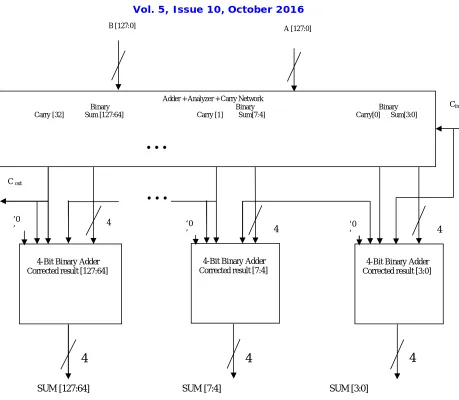
IV.BCD ADDER USING CLA ARCHITECTURE
In order to speed up the BCD adder operation, a new architecture is proposed in this paper. This architecture consists of CLA, analyzer unit to produce digit generate and propagate signals to form carry network. The carry look ahead adder determines whether that bit pair will generate a carry or propagate a carry. The carry network is a parallel prefix network [7], [8]. The carry valve for each digit is computed inside the carry network by using below equation. The network may be parallel prefix or two levels carry look ahead logic and is used for correction.
Output carry = DG+DP.INPUT CARRY …………. (1)
Figure4 shows the complete BCD adder including 4-bit adders for correction. Correction is done by adding 0 or 6 to the binary sum coming from the first level adder. The correction step must be fulfilling two requirements.
Cin
4
4
4
‘0’ 4
C out
B [127:0]
…
.
44-Bit Binary Adder Corrected result [3:0] ‘0
’
4
4-Bit Binary Adder Corrected result [7:4] ‘0
’
Adder + Analyzer + Carry Network
Binary Binary Binary Carry [32] Sum [127:64] Carry [1] Sum[7:4] Carry[0] Sum[3:0]
4-Bit Binary Adder Corrected result [127:64]
…
.
A [127:0]
SUM [127:64] SUM [7:4] SUM [3:0]
Fig. 4 128-bit BCD using CLA
When correction is required the carry input from the carry network and the input values given to the adder and the default value 0 is given as inputs to the first stage of the BCD adder using CLA and if carry produces then the carry from binary adder again acts as an input to the next stage along with usual inputs.
V. RESULT ANALYSIS
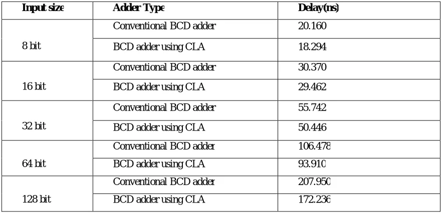
Table 1 Comparison of two BCD adders in terms of delay (ns)
From table 1, it is clear that the BCD adder using CLA is faster when compared with the CBCD Adder. As shown in table 1, BCD adder using CLA for 8, 16, 32, 64 and 128 bit has 1.866 ns,0.908 ns,5.296 ns, 12.568 ns and 35.714 ns delay less respectively when compared with CBCD Adder for respective bit size. So it can be said that the designed BCD adder using CLA is faster.
VI.CONCLUSION
In this paper, BCD adder using CLA is proposed. The BCD adder using CLA is designed for 8, 16, 32, 64 and 128 bit using VHDL and functionally simulated using Isim simulator. The designed adder is synthesized using Xilinx 14.2 ISE EDA tool. In order to compare the performance of designed adder with the existing adder, the existing adder i.e., CBCD adder also designed for the same bit sizes using VHDL, functionally simulated and synthesized using same tool mentioned above. Then the designed adders are compared with each other in terms of delay (ns). As shown in table 7.1, BCD adder using CLA for all bit sizes has minimum delay compared to conventional BCD adder. The BCD adder using CLA has a delay of 18.294 ns, 29.462 ns, 50.446 ns, 93.910 ns and 172.236 ns for 8, 16, 32, 64 and 128-bit size respectively where as CBCD has a delay of 20.160 ns, 30.370 ns, 55.742 ns, 106.478 ns and 207.950 ns for 8, 16, 32, 64 and 128-bit size respectively. So BCD adder using CLA for 8, 16, 32, 64 and 128 bit has 1.866 ns,0.908 ns,5.296 ns, 12.568 ns and 35.714 ns delay less respectively when compared with CBCD Adder for respective bit size. So it can be concluded that the designed adder i.e., BCD using CLA is having less delay when compared to CBCD adder. The BCD adder using CLA can be used for high speed applications.
VII.FUTURE SCOPE
In this paper a high speed BCD adder using CLA is designed. So this adder can be used in the design of high speed ALUs, computational units and processors. But there is a drawback with this adder. The area of adder is increasing with increase in the speed of the adder which in turn increases the power consumption of the adder. So, one can work to decrease the adder area without affecting the speed of the adder.
REFERENCES
[1] A. H. Burks, H. H. Goldstein, and J. von Neumann. Preliminary Discussion of theLogical Design of an Electronic Computing Instrument.
Technical report, Institute forAdvanced Study, June 1946.
[2] M. M. Mano. Digital Design, pages 129–131. Prentice Hall, third edition, 2002.
Input size Adder Type Delay(ns)
8 bit
Conventional BCD adder 20.160
BCD adder using CLA 18.294
16 bit
Conventional BCD adder 30.370
BCD adder using CLA 29.462
32 bit
Conventional BCD adder 55.742
BCD adder using CLA 50.446
64 bit
Conventional BCD adder 106.478
BCD adder using CLA 93.910
128 bit
Conventional BCD adder 207.950
[3] B. Shirazi, D. Y. Y. Young, and C. N. Zhang. RBCD: RedundantBinary Coded Decimal Adder. In IEE Proceedings, Part E, No. 2, volume 136, pages 156–160, March 1989.
[4] “Reduced delay BCD adder”, Alp Arslan Bayrakc¸i and Ahmet Akkas¸ ComputerEngineering Department, Koc University, 2007 IEEE
[5] M. F. Cowlishaw. Decimal Floating-Point: Algorism for Computers. In Proceedings ofIEEE Symposium on Computer Arithmetic, pages 104–
111, June 2003.
[6] M. F. Cowlishaw. Decimal Floating-Point: Algorism for Computers. In Proceedings ofIEEE Symposium on Computer Arithmetic, pages 104–
111, June 2003.
[7] J. D. Thompson, N. Karra, and M. J. SchulteB. A 64-Bit Decimal Floating-PointAdder. In Proceedings of the IEEE Computer Society Annual
Symposium on VLSI, pages297–298, February 2004.
[8] P. M. Kogge and H. S. Stone. A Parallel Algorithm for The Efficient Solution of aGeneral Class of Recurrence Equations. IEEE Trans. on
Computers, C-22(8), Aug. 1973.
[9] VHDL primer by J. Bhaskar
[10] Xilinx 14.2 user manual
[11] Digital design Principles & practices by John F. Wakerly