Optimal Location of UPFC to Optimize the Real
Power Losses and Voltage Stability Limit by Using
Modified Shuffled Frog Leap Algorithm
A.Hemasekhar
1, M.Chethan
2Associate professor, H.O.D Dept. of EEE, S.V.P.C.E.T, Puttur, Andhrapradesh, India 1 PG Student [EPS], Dept. of EEE, S.V.P.C.E.T, Puttur, Andhrapradesh, India 2
ABSTRACT: This paper deals with the Optimal location and control of a unified power flow controller (UPFC) along with transformer taps are tuned to simultaneously optimize the voltage stability limit (VSL) and real power losses of a radial power system network. This problem is deals with a nonlinear equality and inequality constrained optimization problem with an objective function incorporating both the real power loss and VSL. An Meta-Heauristic algorithm known as Modified shuffled frog leap is applied for solving the UPFC location, its injected voltages are in series, a tap positions of secondary side transformers as they are variables. The obtained results of MSFL Algorithm Compared with Bacteria foregoing algorithm using IEEE 39 bus.
KEYWORDS: Modified Shuffled frog leap, continuation power flow (CPF), optimal power flow (OPF).UPFC.
I.INTRODUCTION
The OPF methods are conventional and intelligent and solved by varieties of methods such as successive linear programming, the Newton raphson-based nonlinear programming method, and with varieties of recently proposed interior point methods. The Opf solution is used to optimize a selected objective function such as fuel cost with optimal adjustment of the power system control variables, at the same time satisfying various equity and inequality constraints. The drawback of the Optimal power flow is solved from different analysis, like the effects of load on voltage stability/power flow solvability, generation rescheduling for cost minimization of power generation, controls such as tap control on transformers, shunt devices, and other modern Var sources adjustments to minimize real power losses in the system. The advent of Flexible ac transmission systems (FACTS) system made the possibility for optimizing the power flow without the restoration of generation rescheduling or changes to topology. Unified power flow controller (UPFC) is the advanced in the controller’s family and can provide the OPF with significant flexibility by injecting compensation in series and shunt in controlled manner. The UPFC can provide simultaneous control of all basic power system parameters like (transmission voltages, impedance value and different phase angles).
UPFC is Carried out to establish the investment in putting a UPFC for the cause
II. STATEMENT OF THE PROBLEM
Problem: To solve a voltage secure real power loss minimization of the ten-machine New England power systems [15], connected with UPFC by using SLFA and BFA. Both the sequential and simultaneous allocation of transformer taps and UPFC are carried out for comparison,
A. Test System:
In this paper, the ten-machine, 39-bus power system shown in Fig. 1 is considered for study. The system details, including the 12 transformers nominal tap values, are given in [15].
B. Operating Principle of the UPFC and Its Model:
The UPFC is a unique device in the family of FACTs devices. It consists of a series and shunt connected converters as depicted in Fig. 2.
Fig.2. Basic arrangement of UPFC.
Fig. 3. UPFC injection model.
It can simultaneously control the real and reactive powers of the line and voltage of the bus at which it is connected, by injecting proper magnitude of voltage in series and shunt, respectively. In this paper, one UPFC, with injection model [6], is connected in the system at the suitable location. The UPFC injection model is presented in Fig. 3.
C. continuation power flow:
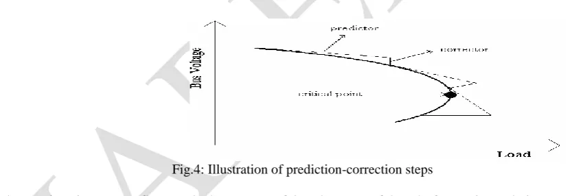
The Jacobin matrix of power flow equations becomes singular at the voltages stability limit. Cpl can overcomes this problem. It finds out successive load flow solutions according to a load scenario. cpl consists of prediction and correction steps. From a base solution, a tangent predictor is used so as to Analyse next solution for a specified pattern of load increase. The corrector step then determines the perfect solution using N-R technique employed by a cpl. After that a new prediction is made for a specified increase in load based upon the new tangent vector.
Fig.4: Illustration of prediction-correction steps
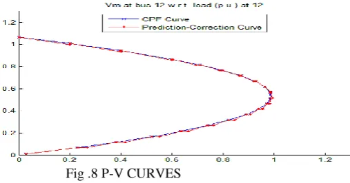
The continuation power flow methods are powerful and very useful tools for getting solution curves for general non-linear algebraic equation by automatically changing the value of a parameter. This solution curve indicates the critical point of voltage stability limit, which is at the nose of the curve. One of the popular CPF techniques is the one developed by Ajjarapu. This paper presents the development of modified continuation power flow (MCPF) to solve the failure in convergence experienced in the conventional power flow. The modified CPF technique was based on the technique proposed by Ajjarapu. The developed technique has also identified the nose point of Q-V curve, which was discovered to be the failure in the conventional power flow.
D. Optimal power flow problem
Algorithm is similar to Memetic Algorithm, which is based on group cooperative search .At the same time, it is also provided with the advantage similar to Particle Swarm Optimization Algorithm. Shuffled Frog Leaping Algorithm has a lot of strong points,such as few parameters, easy to implement and fast convergence Shuffled Frog Leaping Algorithm was applied by all kinds of intelligent optimization systems. For example, Mgmt made use of the Shuffled Frog Leaping Algorithm in the water distribution optimization system in 2003 and Alireza applied th e SFL algorithm in the mixed linear model series in 2007.
. The step by step algorithm are as follows: :
Step1: Create an initial population of P frogs generated randomly. SFLA Population =[X1,X2,…,Xp]p×n Where, P=m×n, N is the number of distributed generation , m is the no of memplexes and n is the number of frogs in memplex. . Step 2: Sort the population increasingly and divide the frogs into m memplexes each holding n frogs such that P=m×n.
Fig.5. Memeplex partitioning process
Step 3: Within each constructed memeplexes, the frogs are effected by other frogs' ideas; hence they experience a meta-heuristics evolution. Me-metic evolution improves the quality of the meme of an individual and enhances the individual frog’s performance towards a goals. Below which are details of me-metic evolution for each memeplexes:
FLOW CHART FOR MSFLA
1V. RESULT AND DISCUSSION
Fig.6. Voltage profile at all buses with MSFLA
In the fig 6, it shows the graph of Voltage with respect to buses Vs Bus numbers. Analysis of voltage levels in bus numbers within per unit value. It is observed that all the bus voltages remain within the limits, and the generator buses maintain their specified voltages when the optimized variables are used.
Fig. 7 Voltage profile at all buses with BFAM
In the fig 7, it shows the graph of Voltage with respect to buses Vs Bus numbers. Analysis of voltage levels in bus numbers within per unit value. The magnitude of voltage (with simultaneous optimization), obtained with MSFLA&BFAM optimization is shown in figure6&7. It is observed that all the bus voltages remain within the limits, and the generator buses maintain their specified voltages when the optimized variables are used.
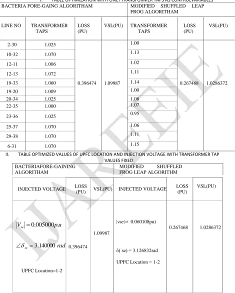
I. TABLE OPTIMIZATION WITH ONLY TRANSFORMER TAPS AS CONTROLVARIABLES
BACTERIA FORE-GAING ALGORITHAM MODIFIED SHUFFLED LEAP
FROG ALGORITHAM
LINE NO TRANSFORMER TAPS
LOSS (PU)
VSL(PU) TRANSFORMER TAPS
LOSS (PU)
VSL(PU)
2-30 1.025
0.396474 1.09987
1.00
0.267468 1.0286372
10-32 1.070 1.13
12-11 1.006 1.02
12-13 1.072 1.11
19-33 1.060 1.14
19-20 1.009 1.00
20-34 1.025 1.08
22-35 1.000 1.07
23-36 1.025 0.95
25-37 1.070 1.06
29-38 1.070 1.11
6-31 1.070 1.15
II. TABLE OPTIMIZED VALUES OF UPFC LOCATION AND INJECTION VOLTAGE WITH TRANSFORMER TAP VALUES FIXED
BACTERIAFORE-GAINING ALGORITHAM
MODIFIED SHUFFLED FROG LEAP ALGORITHM
INJECTED VOLTAGE LOSS
(PU) VSL(PU) INJECTED VOLTAGE
LOSS (PU)
VSL(PU)
u
p
V
se
0
.
005000
.
rad
se
3
.
140000
UPFC Location=1-2
0.396474
1.09987
|vse|=0. u 0.060108pu)
0.267468 1.0286372
δ( se) = 3.126832rad
stability limit (PU) stability limit (PU)
2-30 1.025
V
se
0
.
005000
p
.
u
rad
se
3
.
140000
UPFC Location=1-2
0.396474
1.09987
1.00 |Vse|=0.060108
δ( se) = 3.126832rad
UPFC Location = 1-2
0.267468
1.028637
10-32 1.070 1.13
12-11 1.006 1.02
12-13 1.072 1.11
19-33 1.060 1.14
19-20 1.009 1.00
20-34 1.025 1.08
22-35 1.000 1.07
23-36 1.025 0.95
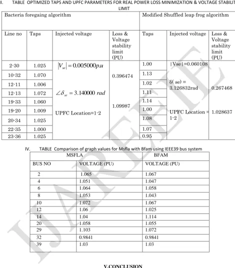
IV. TABLE Comparison of graph values for Msfla with Bfam using IEEE39 bus system
MSFLA BFAM
BUS NO VOLTAGE (PU) VOLTAGE (PU)
2 1.065 1.067
4 1.051 1.047
6 1.064 1.058
8 1.053 1.043
10 1.072 1.067
12 1.06 1.025
14 1.04 1.114
20 1.058 1.055
29 1.103 1.072
32 0.9841 0.9841
39 1.03 1.03
V.CONCLUSION
a view to simultaneously minimize the real power loss and maximize the Voltage stability Limit of the system. UPFC location and its variables along with the transformer taps are simultaneously optimized can even decrease the overall cost function. The results of the multi-objective solution show that the MSFLA technique has provided the better solution as compared to the BFAM.
REFERENCES
[1] P. Ristanovic, “Successive linear programming based OPF solution,” Optimal Power Flow: Solution Techniques, Requirements and Challenges,IEEE Power Eng. Soc., pp. 1–9, 1996.
[2] D. Sun et al., “Optimal power flow by newton approach,” IEEE Trans. Power App. Syst., vol. PAS-103, no. 10, pp. 2864–2875, Oct. 1984. [3] S. Granville, “Optimal power dispatch through interior pont methods,” IEEE Trans. Power Syst., vol. 9, no. 4, pp. 1780–1787, Nov. 1994. [4] G. Torres and V. Quintana, “An interior point method for non-linear optimal power flow using voltage rectangular coordinates,” IEEE Trans.Power Syst., vol. 13, no. 4, pp. 1211–1218, Nov. 1998.
[5] J. L. Martinez Ramos, A. G. Exposito, and V. Quintana, “Transmission loss reduction by interior point methods: implementation issues and practical experience,” Proc. Inst. Elect. Eng., Gen., Transm., Distrib., vol. 152, no. 1, pp. 90–98, Jan. 2005.
[6] M. Noroozian, L. Angquist, M. Ghandhari, and G. Anderson, “Use of UPFC for optimal power flow control,” IEEE Trans. Power Del., vol. 12, no. 4, pp. 1629–1634, Oct. 1997.
[7] G. Glanzmann and G. Andersson, “Coordinated control of FACTS devices based on optimal power flow,” in Proc. 37th Annu. North Amer.Power Symp., Ames, IA, Oct. 23–25, 2005.
[8] V. Ajjarapu and C. Christy, “The continuation power flow: a tool for steady state voltage stability analysis,” IEEE Trans. Power Syst., vol. 7, no. 1, pp. 416–423, Feb. 1992.
[9] F. Milano, C. A. Canizares, and A. J. Conejo, “Sensitivity-based security- constrained OPF market clearing model,” IEEE Trans. Power Syst., vol. 20, no. 4, pp. 2051–2060, Nov. 2005.
[10] J. Yuryevich and K. P. Wong, “Evolutionary programming based optimal power flow algorithm,” IEEE Trans. Power Syst., vol. 14, no. 4, pp. 1245–1250, Nov. 1999.
[11] A. A. A. Esmin, G. Torres, and A. C. Z. de Souza, “A hybrid particle swarm optimization applied to loss power minimization,” IEEE Trans.Power Syst., vol. 20, no. 2, pp. 859–866, May 2005.
[12] M. Eusuff, K. Lansey, F. Pasha; “Shuffled frog-leaping algorithm: a memetic meta-heuristic for discrete optimiza-tion”, Engineering Optimization, 2006, Vol. 38, No. 2, pp.129–154.
BIOGRAPHY
A.Hema sekhar He received his B.Tech (Electrical and Electronics Engineering) degree from JNTU,Hyderabad, at Sree Vidyaniketan Engineering College, Rangampet; M.Tech (PSOC) from the S.V.University college of Engineering,Tirupati.He is currently working as Associate Professor & Head of the Dept. of Electrical and Electronic Engineering, S.V.P.C.E.T,Puttur. His area of interest power systems, operation and control, distribution systems, electrical machines. ,Power Stability