ISSN (Print) : 2320 – 3765 ISSN (Online): 2278 – 8875
I
nternational
J
ournal of
A
dvanced
R
esearch in
E
lectrical,
E
lectronics and
I
nstrumentation
E
ngineering
(A High Impact Factor, Monthly, Peer Reviewed Journal)
Website: www.ijareeie.com
Vol. 8, Issue 3, March 2019
Implementation of Control Panel Using PLC
for 750 Ton Expander Hydraulic Press
K.Dhivya[1],P.Divahar[2],S.Manoharan[3],I.Marimuthu[4],S.Vignesh[5]
[1]
Assistant Professor, Department of Electrical and Electronics Engineering, Jai Shriram Engineering college,
Tiruppur, Tamilnadu, India
[2][3][4][5]
U.G Scholar, Department of Electrical and Electronics Engineering, Jai Shriram Engineering college,
Tiruppur, Tamilnadu, India.
ABSTRACT: Industries are grown drastically in now-a-days without influence of human being, this is achieved only through automation. In this project we designed a press for 750 Expander Hydraulic press integrated by induction motor. It can perform two operations that are cold molding and hot molding. The main advantage of using induction motor is to save the power consumption upto 30%. Linear Variable Displacement Transducer (LVDT) is mainly used to control the position of moving object. The total setup is controlled by the ladder logic, which is framed by PLC. It is real time system and suitable for flexible and accurate operation of the machine program is written through total integrated automation. PLC are available in the various models, but SIMATIC S7 1250 is used in the project. It will indicate the fault and overload condition. The control panel is designed for 750 ton expander. Machine is designed for making the vehicle rim structure. The panel consists of PLC Kit, Transformer, SMPS, protection and safety circuit. Main purpose of panel board wiring is to reduce the complexity of the system hardware. The induction motor is controlled by the Variable Frequency Driver (VFD) Circuit. The output terminal from the PLC is connected to valves and motor, alarm etc.
KEYWORDS: LVDT, induction Motor, PLC, HMI, E-PLAN
I. INTRODUCTION
The Industry does not run without machines which are invented by the man for reducing his work time and increase the production. In the starting point, the controlling the process of machine is done by the isolator which trip the circuit totally when the fault is occurs. This will stop the production and involve the manual operation to retain the normal condition in later this is overcome by the placing relay and the other protective device. This will increase the
complexity and the identification of the fault is difficult, usage of relay[1] is high because its operation is either open or
close. This will increase the cost and need more maintenance. To overcome this, we use the PLC and relay for reducing the cost and increase the production. The main advantage of using the PLC is the fault is easily identified and it can be easily modified the logics for the required specification. Power consumption is very less and operating frequency is high and the program is executed very fast.
1.1 Previous Method
ISSN (Print) : 2320 – 3765 ISSN (Online): 2278 – 8875
I
nternational
J
ournal of
A
dvanced
R
esearch in
E
lectrical,
E
lectronics and
I
nstrumentation
E
ngineering
(A High Impact Factor, Monthly, Peer Reviewed Journal)
Website: www.ijareeie.com
Vol. 8, Issue 3, March 2019
1.2 Proposed Method
Comparing the past method we can use induction motor instead of induction motor. The main advantage of the motor is it can operate any supply. It can operate in both the supply AC and DC but we use only AC induction motor. The induction motor is works on the induction mechanism. Position is send as feedback for the motor operation. This is controlled by VFD driver circuit. It can turn off when the curing time of the material is takes place, at this time the energy is saved up to 30%. It will reduce the power consumption and electricity bill. Proximity sensor is replaced by LVDT. It is easy to identify the movement of the bolster. The main advantage of the LVDT is it can control the production of the product and cost is low comparing to the previous setup. There is no need for the additional pump setup.
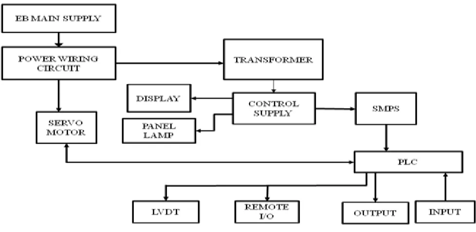
1.3 Architecture
The architecture for the setup is shown in Fig 1.0. Power wiring circuit contains mould case circuit breaker,
Miniature circuit breaker, Current transformer, Single phase preventer. The purpose of current transformer[6] is to sense
the current rating of each phase. Single phase preventer is used to prevent the circuit from the fault when over voltage is occur.
Fig 1.3.1 Architecture of the system
II. OPERATION TOOL
2.1 Induction motor
An induction motor or asynchronous motor is an AC electric motor in which the electric current in the rotor needed to produce torque is obtained by electromagnetic induction from the magnetic field of the stator winding.[1] An induction motor can therefore be made without electrical connections to the rotor.[a] An induction motor's rotor can be either wound type or squirrel-cage type.
Three-phase squirrel-cage induction motors are widely used as industrial drives because they are
self-starting, reliable and economical. Single-phase induction motor[4] are used extensively for smaller loads, such as
ISSN (Print) : 2320 – 3765 ISSN (Online): 2278 – 8875
I
nternational
J
ournal of
A
dvanced
R
esearch in
E
lectrical,
E
lectronics and
I
nstrumentation
E
ngineering
(A High Impact Factor, Monthly, Peer Reviewed Journal)
Website: www.ijareeie.com
Vol. 8, Issue 3, March 2019
compressor load applications. Squirrel cage induction motors are very widely used in both fixed-speed and variable-frequency drive (VFD) applications.
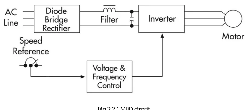
2.2 VFD Driver Circuit
Fig 2.2.1 VFD circuit
The driver circuit is shown in Fig 2.2.1 which is position is send as feedback, the AC supply is given to the bridge rectifier. The capacitor and inductor is act as filter circuit to eliminate the harmonics. And the output voltage is fed to the inverter which is used to invert the power supply to the motor the voltage and the frequency is controlled according to the operation. The efficiency of the driver circuit is about 92% - 98%, the remaining 2% is loss due to heat dissipated by the circuit.
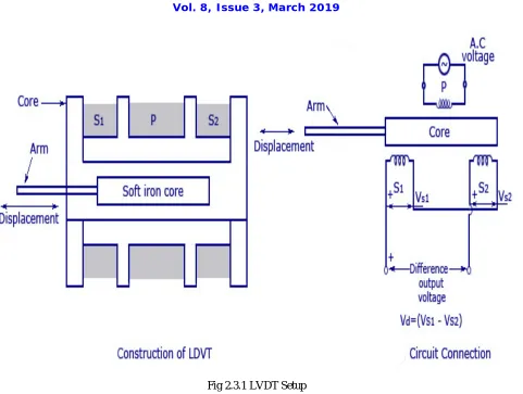
2.3 LVDT
The LVDT is used to monitor the position of the moving bolster. It consists of three solenoid coils which are faced opposite to each other. The core is placed between the coils. The movement of the core which causes induced voltage to change. The change in voltage will cause the changes in movement of bolster. It can operate up to high
temperature of 12000 F. The operating voltage for the LVDT is 24 V DC. It is mainly used in the induction motor for
the position feedback control. We use BALLUFF LVDT for this operation. It can withstand up to 850F.The over
ISSN (Print) : 2320 – 3765 ISSN (Online): 2278 – 8875
I
nternational
J
ournal of
A
dvanced
R
esearch in
E
lectrical,
E
lectronics and
I
nstrumentation
E
ngineering
(A High Impact Factor, Monthly, Peer Reviewed Journal)
Website: www.ijareeie.com
Vol. 8, Issue 3, March 2019
Fig 2.3.1 LVDT Setup
2.4 Relay
The relay is mainly used for the protective purpose either it may turn ON or turn OFF. In this we use the transistor module relay for the operation. The transistor relay consists of 8 individual relay which is called as set. The relay is available in open condition when the supply flows the switch is closed by the energisation of the coil.
2.5 SMPS
SMPS stands for Switched Mode Power Supply. Its operated frequency is 50/60 HZ. The current rating of the SMPS is 20A. The input supply voltage is AC up to 240V. The output voltage is constant 24V DC for the PLC inputs.
2.6 HMI
Human Machine Interface which is used for communication between the user and the CPU. It is operated on the 24V DC supply. The lower limit of the operating voltage is 19.2 V and the maximum operating limit of the voltage is about 28.8V DC. The current consumption of the HMI is about 0.5A. It can support the HTTP, HTML, CSS, XML, and JAVA Script. The CAN bus protocol is not supported here. Ethernet and MODBUS is suited for the communication. It contains the library files.
2.7 Solenoid Valve
ISSN (Print) : 2320 – 3765 ISSN (Online): 2278 – 8875
I
nternational
J
ournal of
A
dvanced
R
esearch in
E
lectrical,
E
lectronics and
I
nstrumentation
E
ngineering
(A High Impact Factor, Monthly, Peer Reviewed Journal)
Website: www.ijareeie.com
Vol. 8, Issue 3, March 2019
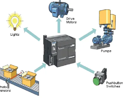
2.8 PLC
The PLC stands for Programming Logic Controller here we use Master as CPU SIMATIC S7-1250 PLC. This PLC consists of 14 pins input and 10 pins as output operating voltage is 24V DC supply and maximum permissible operating voltage (upper limit) is 28.8 V DC. The minimum permissible operating voltage (lower limit) is 20.4V DC. The rated current when the CPU alone is operated is 500mA. The maximum amount of current consumption is about 1500mA, when all the expansion modules are operated or connected. There is no expandable memory only 100 KB is
used for the program. Here we used only two analog modules[2] as an output. If we want more than two slave bits, we
must use the additional CPU.
Fig 2.8.1 Architecture of PLC
III. DRAWING TOOL
ISSN (Print) : 2320 – 3765 ISSN (Online): 2278 – 8875
I
nternational
J
ournal of
A
dvanced
R
esearch in
E
lectrical,
E
lectronics and
I
nstrumentation
E
ngineering
(A High Impact Factor, Monthly, Peer Reviewed Journal)
Website: www.ijareeie.com
Vol. 8, Issue 3, March 2019
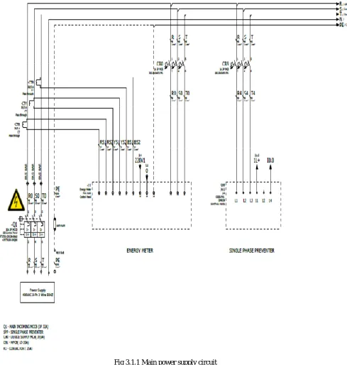
3.1 Main power supply circuit
The main power supply circuit consists of MCCB which is used to protect the device from the over current or over voltage the Amps rating of the MCCB is 32A, which is placed according to the connection of the load. CT is placed on every phase of the supply voltage to monitoring the current rating of incoming buses. The CB0 is provided
for protection of energy meter[5] another circuit breaker CB9 is connected for the protection for single phase preventer.
ISSN (Print) : 2320 – 3765 ISSN (Online): 2278 – 8875
I
nternational
J
ournal of
A
dvanced
R
esearch in
E
lectrical,
E
lectronics and
I
nstrumentation
E
ngineering
(A High Impact Factor, Monthly, Peer Reviewed Journal)
Website: www.ijareeie.com
Vol. 8, Issue 3, March 2019
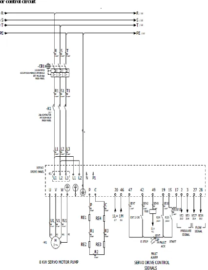
3.2 Motor control circuit
.
ISSN (Print) : 2320 – 3765 ISSN (Online): 2278 – 8875
I
nternational
J
ournal of
A
dvanced
R
esearch in
E
lectrical,
E
lectronics and
I
nstrumentation
E
ngineering
(A High Impact Factor, Monthly, Peer Reviewed Journal)
Website: www.ijareeie.com
Vol. 8, Issue 3, March 2019
The motor is connected with driver circuit[8] and device is protected with MPCB. Supply is fed for the induction motor
through circuit breaker 1 and contactor through star delta starter. The position of the motor is feed back through induction driver circuit signaling by LVDT. The fault alarm is connected to driver circuit.
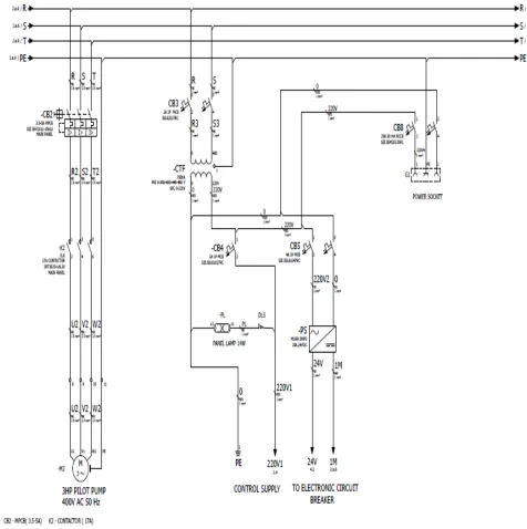
3.3 SMPS and PLC input circuit
ISSN (Print) : 2320 – 3765 ISSN (Online): 2278 – 8875
I
nternational
J
ournal of
A
dvanced
R
esearch in
E
lectrical,
E
lectronics and
I
nstrumentation
E
ngineering
(A High Impact Factor, Monthly, Peer Reviewed Journal)
Website: www.ijareeie.com
Vol. 8, Issue 3, March 2019
IV. PLC TIA AND FLOWCHART
4.1 TIA
The software used for the system is TIA –TOTAL INTEGRATED AUTOMATION. It is whole controlled
operating tool (which can control all the equipment which is mounted on the system which includes HMI, SCADA etc.). This is user friendly and innovative capability and efficient working steps or algorithm for TIA is below
Step 1: Start.
Step 2: Create a new project. Step 3: Add devices.
Step 4: Add Device configuration. Step 5: Communication through Ethernet. Step 6: Program downloading.
Step 7: Program execution in machine Step 8: Stop.
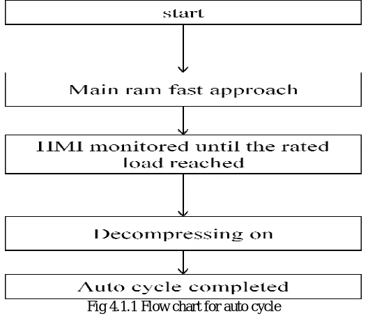
4.2 FLOWCHART
The flow path of Auto cycle is shown in below
Fig 4.1.1 Flow chart for auto cycle
V. CONCLUSION
Thus in all the industries the product manufacturing operation is done by manual which cause the accident due to his lack of concentration. To overcome this machines are introduced to perform the operation automatically. Here the machines are monitor by the way of PLC program. The PLC operation involves the operation with SCADA which is very easy to operate from the PC itself. Thus the operating time is get reduced with high production and saving of electricity up to 30% by using induction motor in the place of induction motor. The wiring complexity is reduced by connecting the relay. PLC program was designed for controlling the machine either automatic or manual. It is undergone to stress relief process. Designed frame is under gone to the floor boring section .After floor boring it is taken for the painting and assembled in the assemble section. The final inspection is performed in the assembly and production is checked according to the load arrangement. The machine is dismantled for repainting and ready for dispatch.
ISSN (Print) : 2320 – 3765 ISSN (Online): 2278 – 8875
I
nternational
J
ournal of
A
dvanced
R
esearch in
E
lectrical,
E
lectronics and
I
nstrumentation
E
ngineering
(A High Impact Factor, Monthly, Peer Reviewed Journal)
Website: www.ijareeie.com
Vol. 8, Issue 3, March 2019
REFERENCES
1.Avvaru Ravi Kiran,2013, ”THE PRINCIPLE OF PROGRAMMING LOGIC CONTROLLER AND ITS ROLE IN AUTOMATION”. International Journal Of Engineering Trends and Technology,Volume4.Issue3
2.Ms.V.Preetha,Mr.Nambirajan.P,April2016,”AUTOMATIC CONTROL OF HYRAULIC MACHINE USING PLC” ,International Journal Of Science Technology & Engineering ,Volume 2,Issue 10.
3 Rathod Balasahep .S , Sathis.M.Rajmane,April 2013,”A CASE STUDY ON DESIGEN OF A FLY WHEEL FOR PUNCHING PRESS OPERATION”, IJEAT,Volume 3.
4.A.Shivasankar,G.Prabhakaran,R.Dhanabal,A.Muthu Krishnan, ,”DASIGEN AND IMPLEMENTATION OF PLC BASED CONTROL PANEL FOR HYDRAULIC ASSEMBLY PRESS” in IJAREEIE, Volume 6, Issue 3 March 2017.
5. “Development of seal Pressing Arrangement in Front AxleAssembly”,Prithiviraj.B,Hemadri.C,VasaRamu,Velmurugan.V,Sanlkar.K, IJARMET Vol 2,Issue 2,(Apr-June 2016).
6. “OMRAN SELECTION GUIDE”, Vol.3-2013
7.” Flochova. J Auxt .F ,May 2007,”DECISION AND CONTROL”,IEEE transaction on automation desigen,Vol.46,no.pp.1874-1879.