Wind Energy Conversion System Integrated
with Grid under Variable Speed Scenario
Haroon Ashfaq
1, Surendra Kumar Tripathi
2Assistant Professor, Department of Electrical Engineering, Jamia Millia Islamia, New Delhi, India 1 Research Scholar, Department of Electrical Engineering, Jamia Millia Islamia, New Delhi, India 2
ABSTRACT: The recent sensitive issue of climate change is due to the extensive amount of carbon emission through the consumption of fossil fuel as the primary option for energy demand. Due to the negative impact of green house effect, the alternative and renewable energy options have received significant attention global scale. The two branched approach of renewable energy projects including the reduction in the global greenhouse gas emissions and encouragement to the development of alternate green energy options like wind energy. Wind energy has become one of most acceptable solution among the different renewable energy resources because of the application of power electronic based controllers that allows the wind energy conversion system (WECS) to generate quality electric power irrespective of variable wind profile. The continuous flow of quality power from WECS to grid is insured for wider range of wind speed. Doubly fed induction generator (DFIG) used in WECS having power electronic converter which requires very small friction of power in comparison to the total generation capacity. This paper brings out the analysis of a DFIG system in terms of its stator and rotor currents and real and reactive power balance when the machine is operating with varying wind velocity conditions. Various possible maximum power point tracking techniques are listed in the paper. The suitable Maximum power point tracking (MPPT) technique has also been suggested to harness maximum available power for a given wind velocity to ensure the continuous power flow from WECS to the power grid.
KEYWORDS: Wind Energy Conversion System (WECS), Double feed induction generator (DFIG), Matrix converter (MC), Back to back converter, Maximum power point tracking (MPPT), Wind turbines(WT), Wind generators(WG).
I. INTRODUCTION
With the development of wind power generation the green energy trend is being projected and flourished globally. Increased amount of electricity produced from WECS is one of the ways to reach the goal of lowering emissions of greenhouse gases from energy production. Installed wind turbines and wind power plants have increased both in size and number in recent years significantly. However, research is still required to ensure the reliability of grid connected wind energy conversion system. Many techniques have been proposed in various research work which discuss the smooth mechanical to quality electrical energy conversion can be realized, have been proposed and developed with commercial success [1]-[2].
ISSN (Print) : 2320 – 3765 ISSN (Online): 2278 – 8875
I
nternational
J
ournal of
A
dvanced
R
esearch in
E
lectrical,
E
lectronics and
I
nstrumentation
E
ngineering
(An ISO 3297: 2007 Certified Organization) Vol. 4, Issue 2, February 2015
Power System Stability
Rotor Angle Stability [7] Frequency Stability [3] Voltage Stability [6] Small Disturbance Angle Stability [4] Transient Stability [5] Short Term Long Term Large Disturbance Voltage Stability [8] Small Disturbance Voltage Stability [9] Short Term Long Term Short Term
Fig. 1 Classification of Power System Stability
The rotor angle stability governs the small disturbance angle stability and the transient stability. This is important to ensure the quality power during wind gusts. This has short term effect. Another important parameter is the frequency stability which is having short term as well as long term effect depending on the wind quality. Voltage stability is the compliment of small disturbance voltage stability and large disturbance voltage stability [6], [7]. This also has the short term and long term stability issues. The detailed comparison is shown in the above Fig. 1.
In case of renewable power generation the wind energy has been identified as the most swiftly growing technology with the development up to the megawatts capacity of wind turbines with the large power generators and power electronic converters.. Recently, voltage source converter (VSC) based doubly fed induction generator (DFIG) is considered to be highly reliable and efficient. To harness maximum amount of wind energy under varying wind velocity conditions, Doubly Fed Induction Generator (DFIG) seems to be one of the promising options, although various other generators such as Squirrel Cage Induction Generators (SCIG) and Permanent Magnet Synchronous Generators (PMSG) are also emerging as tough competitors to DFIG. Based on electrical topology, wind turbine generators are broadly grouped in to four categories namely (i) Fixed speed SCIG (ii) Variable slip (wound rotor) induction generator with variable rotor resistance (iii) Variable speed DFIG with partially rated converter interface (iv) Variable speed generators (either SCIG or PMSG) with full converter interface [8],[9].
It is very important to assure that the grid is capable of staying within the operational limits of voltage and frequency for all expected combination of WECS and consumer load and at the same time maintaining transient stability of connected grid.
II. POWER CHARACTERISTICS OF WIND TURBINE
Pwt = 0.5 Cp(λ, β) ρ A v3 (1)
where v is the wind speed, ρ is the air density, A is the area swept by the blades and Cp is the wind power coefficient (denotes power extraction efficiency which is a function of β and λ, β being the pitch angle and λ being the tip speed ratio – TSR given by R Ω / v where R is turbine radius, Ω is turbine shaft speed). Thus, power captured by the wind turbine is heavily dependent upon TSR when β is unchanged. The power conversion efficiency has a well determined maximum Cp,max for a specific tip speed ratio λ. The optimal control of active power in a variable-speed fixed-pitch WECS can therefore be easily achieved, if λ is controlled for attaining the Cp,max corresponding to a given wind velocity [10]-[12]. From equation (1) and expression for λ, it follows that
Pwt = 0.5 Cp(λ, β) ρ π R 2
v3
= 0.5 {Cp(λ) / λ3} ρ π R5 Ω3 (2) Thus the torque produced by the turbine is computed as
Twt = Pwt / Ω (3)
Hence the torque produced by the turbine is proportional to Ω2 and power is proportional to Ω3 . So, by the above equations it can be seen that for a particular TSR, the power extracted by the turbine is maximum for a given wind velocity.
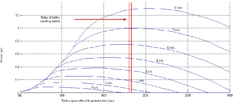
Fig. 2 Power curves of a typical wind turbine.
This is equivalent to maintaining the tip speed ratio at its optimal value λopt and can be achieved by operating the turbine at a variable speed, corresponding to the wind speed. Fig. 2 represents the power curves of a typical wind turbine of wind energy conversion system (WECS).
III. WIND GENERATORS
ISSN (Print) : 2320 – 3765 ISSN (Online): 2278 – 8875
I
nternational
J
ournal of
A
dvanced
R
esearch in
E
lectrical,
E
lectronics and
I
nstrumentation
E
ngineering
(An ISO 3297: 2007 Certified Organization) Vol. 4, Issue 2, February 2015
A. FIXED SPEED INDUCTION GENERATORS (FSIG)
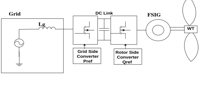
The fixed speed induction generator (FSIG) is consisting of squirrel cage induction generator that is coupled through a gearbox to the wind turbine rotor as shown in Fig. 3. This type of wind turbine is simple and cheap. The well-known advantages of FSIG are it is robust, easy and relatively cheap for mass production. In addition, it enables stall-regulated machines to operate at a constant speed when it is connected to a large grid, which provides a stable control frequency. Although the stall control method is usually used in combination with the fixed speed FSIG for power control, the active stall control or pitch control have also been applied.
But it has reported various disadvantages like lack of control possibilities of both active and reactive power, gearbox breakdown due to large mechanical loads (because of power fluctuations are converted to torque pulsations) and the large fluctuations in output power. Due to these reasons, wind turbine manufacturers are increasingly interested in variable speed devices.
WT
FSIG
Grid Side Converter
Pref
Lg Grid
Rotor Side Converter
Qref DC Link
Fig. 3 WECS using Fixed Speed Induction Generator
B. DOUBLY FED INDUCTION GENERATORS (DFIG)
The doubly fed induction generators (DFIG) are wound rotor induction generator. The DFIG is based on the concept, which corresponds to a variable speed wind turbine configuration with a wound rotor induction generator (WRIG) and a partial-scale power electronic converter on the rotor circuit, as illustrated in Fig. 4. The stator is directly connected to the grid, whereas the rotor is connected through a back to back power electronic converter. The power converter controls the rotor frequency and thus the rotor speed. This concept supports a wide speed range operation, depending on the size of the frequency converter. Typically, the variable speed range is +30% around the synchronous speed. The rating of the power electronic converter is only 25–30% of the generator capacity, which makes this concept attractive and popular from an economic point of view.
WT DFIG
T/F
DC Link
Grid Side Converter Lg
Grid
Rotor Side Converter
Fig. 4 WECS using Doubly Fed Induction Generator
C. SYNCHRONOUS GENERATORS (SG)
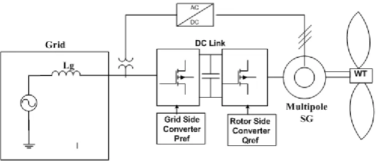
Synchronous generators (SG) are considered one of the most-promising technologies for multi- mega watt (MW) wind-energy conversion systems. The synchronous generators can be classified into the electrically excited synchronous generator (EESG) and the PMSG. Excitation is provided either with rotor windings or permanent magnets. Hence, full-scale power converters (FSCs) are needed, and a reduced full-scale converter for the excitation is required for synchronous machines without permanent magnets. Wind energy conversion system using synchronous generator with power control connected with power grid is shown in Fig. 5.
Fig. 5 WECS using Synchronous Generator
IV. MPPT FOR ENERGY CAPTURE
ISSN (Print) : 2320 – 3765 ISSN (Online): 2278 – 8875
I
nternational
J
ournal of
A
dvanced
R
esearch in
E
lectrical,
E
lectronics and
I
nstrumentation
E
ngineering
(An ISO 3297: 2007 Certified Organization) Vol. 4, Issue 2, February 2015
representing the power curve of a typical wind turbine, the operating condition for the optimum output can be obtained for various wind speed values. Intelligent control strategies for energy optimization include the data-mining methods, which also consider the power demand from the utility grid, as well as MPPT techniques. On the basis of literature survey the various possible MPPT techniques which are currently in practice are identified [16] - [21]. They are listed below-
Algorithms for searching optimum operating point.
Power system stabilizers (PSS) in DFIG system improves the damping of oscillations in the network.
Flux magnitude angle control (FMAC).
Hill climbing search (HCS).
Tip speed ratio (TSR) control.
Power Signal Feedback (PSF) control for dynamic stability control.
Optimal Torque (OT) control.
Mapping power technique in which maps/curves are used to find out the optimum point.
Anemometer method which uses the predetermined look up table.
MPPT by maximum efficiency control and a maximum torque control.
Advance hill climb search (AHCS) technique.
MPPT algorithm by directly adjusting the DC/DC converter duty cycle.
MPPT algorithms by changing the speed reference in the desired direction.
MPPT using two converters and by adjusting the switching frequencies of the two converters achieve maximum power tracking g and output voltage regulation.
Using matrix converter in DFIG.
Using MPPT algorithms with current feedback.
Sliding mode control using fuzzy for variable speed wind turbine.
Unity power factor and maximum power point tracking using loop control.
Maximum Power Point Tracking based on adaptive control strategy.
Adjustment of gear ratio with the change of wind speed to achieve the maximum power from the system.
Neural network techniques
The above mentioned MPPT techniques are also used to forecast the wind to achieve higher energy conversion efficiency to ensure the significant WECS contribution in power sector. The significant purpose of the MPPT is to ensure the tip speed ratio of the wind turbine as close as possible to optimal tip speed ratio. As the operation conditions are wind profile dependent therefore all the MPPT methods identified are not suitable for all kind of wind generators. Sliding mode control, P & O, adjustment of gear ratio, optimal torque control methods of MPPT are found to be suitable for small rating WECS. They have slow and sluggish response. MPPT techniques like HCS, AHCS, TSR, anemometer method, MPPT algorithms by changing the speed reference and mapping power technique in which the maps/curves are used to find out the optimum point of operation which works well in the smooth wind conditions only. They are complex and less reliable P&O, TSR, PSF, HCS and PSS MPPT techniques are widely employed in wind generators. As P & O does not require prior knowledge of maximum wind turbine power at different wind velocity and electric machine parameters. In TSR method the instantaneous tip speed ratio value is calculated on-line. PSF improves the dynamic stability control of WECS. HCS technique is most preferred in small capacity WECS for smooth wind speed. PSS technique improves the damping of oscillations in the network.
The suitable MPPT techniques enhance the net power capture. The basic and important advantage of the MPPT is to operate the WECS at variable wind profile with optimum output. This contributes significantly in the development and growth of WECS to increase its participation in the net global power generation.
V. PROPOSED CONVERTER CONTROL
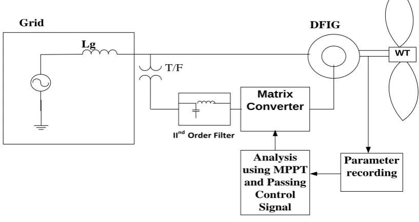
corresponding signals are fed to the control unit performing the maximum power point tracking operation. On the basis of the signals from the parameter recording unit and the MPPT control unit the corresponding signals are fed to the matrix converter unit as shown in Fig. 6. The slip value varies accordingly. The slip power flows from and to the rotor circuit through the Rotor Side Converter for the super and sub-synchronous operation modes of operations respectively.
WT DFIG
T/F Lg
Grid
IInd Order Filter
Matrix Converter
Parameter recording Analysis
using MPPT and Passing
Control Signal
Fig. 6 Proposed DFIG-based WECS Control
The sub-synchronous and the super-synchronous modes of operation are investigated separately during optimization process. Hence as per the mode of operation the controlling strategy is implemented accordingly as mentioned in table1.
Super-synchronous mode Sub-synchronous mode
-1 ≤ S ≤ 0 0° ≤ α1 ≤ 90°
90° ≤ α2 ≤ 180°
0 ≤ S ≤ 1 90° ≤ α1 ≤ 180°
0° ≤ α2 ≤ 90°
TABLE 1 Operation Condition of DFIG
Where α1 and α2 are the firing angles for converter1 (RSC) and converter2 (GSC). Under these constraints, the net
output power from the DFIG is maximised for different values of the wind speeds and the corresponding firing angles of the converters are determined.
Generator (Power Range)
Converter Options Device Count (Semiconductor Cost)
Control Schemes
Diode Bridge/SCR Inverter
DC-Link Capacitor 6 Controllable Switches
(Low)
Sliding Mode Control
ISSN (Print) : 2320 – 3765 ISSN (Online): 2278 – 8875
I
nternational
J
ournal of
A
dvanced
R
esearch in
E
lectrical,
E
lectronics and
I
nstrumentation
E
ngineering
(An ISO 3297: 2007 Certified Organization) Vol. 4, Issue 2, February 2015
DFIG (kW-MW)
Inverter 12 Controllable Switches (Moderate) Back-to-Back
Hard-Switching Inverters
DC-Link Capacitor 12 Controllable Switches
(Moderate)
Vector control of rotor and supply side Space Vector Modulation or PWM MPPT, Space Vector Control
Matrix Converter 18 Controllable Switches (High)
Vector control of rotor and supply side Double Space Vector PWM switching
TABLE 2 Summary of Wind Energy Conversion Systems using DFIG
Table2 gives the summary of wind energy conversion system using DFIG for various generator-converters topologies. The cost of the overall system increases as the complexity of the power electronic converter increases. The intricacy of the controller design also affects cost; for example the use of MPPT techniques would cost more than a simple look-up table method. However higher order control and converter designs may increase efficiency of the overall system. The inclusion of a DC-boost stage helps reduce the control complexity of the grid inverter at a small increase in cost. Likewise, replacing the diode rectifier with a controlled rectifier allows for a wider range of control of both the generator and grid real and reactive power transfer.
VI. SIMULATION STUDY AND RESULTS
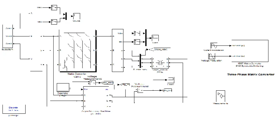
The proposed DFIG based WECS using matrix converter topology described above is simulated using MATLAB at variable wind velocities to operate the system at sub synchronous and super synchronous speed as shown in Fig. 7. The various parameters like stator current, rotor current, real power and reactive power were analysed.
Fig. 7 DFIG based WECS using Matrix Converter
Fig. 8Stator Current I_a (pu)
Stator current for phase ‗b‘ is shown in Fig. 9. The result shows that it stabilises before 0.2 sec and the quality current is achieved.
Fig. 9Stator Current I_b (pu)
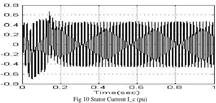
Stator current for phase ‗c‘ the stator current is shown in Fig. 10. It is observed that the stable operation is achieved.
Fig 10Stator Current I_c (pu)
ISSN (Print) : 2320 – 3765 ISSN (Online): 2278 – 8875
I
nternational
J
ournal of
A
dvanced
R
esearch in
E
lectrical,
E
lectronics and
I
nstrumentation
E
ngineering
(An ISO 3297: 2007 Certified Organization) Vol. 4, Issue 2, February 2015
Fig. 11 Rotor Current I_a (pu)
The rotor current for the phase ‗b‘ it is shown in Fig.12 below. It is observed that the rotor current is stable.
Fig. 12Rotor Current I_b (pu)
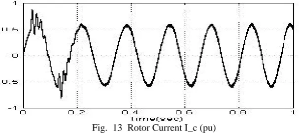
Fig. 13 represents the rotor current for phase ‗c‘. The stable and quality power is obtained.
Fig. 13 Rotor Current I_c (pu)
Fig. 14 Real power (MW)
The real power obtained from the proposed WECS is shown in Fig. 14. It is observed that the stable and quality power is generated at variable speed wind profile using matrix converter.
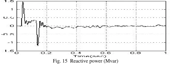
Fig. 15 Reactive power (Mvar)
The reactive power characteristic is shown in Fig. 15. From the results it is observed that the application of suitable filter with the matrix converter; the harmonic contents in the stator and rotor currents are mitigated this ensures the better power quality. The real power characteristic shows that it met the requirement which insures the grid integration of WECS. The reactive power characteristic ensures the smooth and satisfactory operation of WECS integrated with power grid. The use of DFIG with matrix converter in wind turbines is emerging rapidly and more and more research is being done in many areas of study relating to the use of such a system for extracting wind energy for electricity generation.
VII. CONCLUSION
It is concluded that the power-electronic technology plays a very important role in the integration of renewable energy sources into the power grid under variable wind scenario. The popularity of DFIG systems are due to its competitive advantages over other types of generators and hence are more widely being used in large power grids in order to add power to the grid. Smaller systems do not usually use DFIG systems due to the complexity involved in the use and control of power electronics involved. In the paper it is demonstrated that the suitable MPPT method for the wind energy conversion system including an MC ensures the maximum possible quality power generation at variable wind profile. The controller equipped with the MPPT algorithm controls to maximize the power captured from the wind turbine. This is possible by adjusting the MC control. The simulation results show that the performance of the grid connected WECS is better at variable wind profile using matrix converter.
REFERENCES
[1] Zhang, D., Zhang, X., He, J. , and Chai, Q. ,―Offshore wind energy development in China: Current status and future perspective,‖ Renew.
Sustain. Energy Rev., vol. 15, no. 9, pp. 4673–4684, 2011.
[2] Margaris, I. D., Hansen, A. D., and Cutululis, N. A. , ―Impact of wind power in autonomous power systems—Power fluctuations—Modelling and control issues,‖ Wind Energy, vol. 14, no. 1, pp. 133–153, 2011.
ISSN (Print) : 2320 – 3765 ISSN (Online): 2278 – 8875
I
nternational
J
ournal of
A
dvanced
R
esearch in
E
lectrical,
E
lectronics and
I
nstrumentation
E
ngineering
(An ISO 3297: 2007 Certified Organization) Vol. 4, Issue 2, February 2015
[4] Pal, B. C., and Mei, F., ―Modelling adequacy of the doubly fed induction generator for small-signal stability studies in power systems,‖ IET
Renew. Power Generat., vol. 2, no. 3, pp. 181–190, 2008.
[5] Meng, W. , Yang, Q. , Ying, Y. , Sun, Y. , Yang, Z. , and Sun, Y. , ―Adaptive power capture control of variable-speed wind energy conversion systems with guaranteed transient and steady-state performance,‖ IEEE Trans. Energy Convers., vol. 28, no. 3, pp. 716–725, 2013.
[6] Ashfaq, H., and Tripathi, S.K., ―Output Maximization of Grid Connected Wind Energy Conversion System using Doubly Fed Induction Generator‖, 6th International Conference on Advanced Computing and Communication Technologies(ICACCT-2012), Vol. 3, pp. 277-282, 2012. [7] Ashfaq, H., and Jamil Asghar, M.S., ―Performance improvement of grid-connected wound rotor induction generators‖, IEEE Power India Conference, 2006, pp. 1-5, 2006.
[8] Ashfaq, H., and Asghar, M.S.J., ―Optimum Input Volt-Ampere Control of Three-Phase Induction Motors Connected to Distributed Generating Systems‖, Power Electronics and Drives Systems, 2005. PEDS 2005. International Conference, Vol.1, pp.486-488, 2005.
[9] Chen Wang, Liming Wang, Libao Shi, and Yixin N, ― A Survey on Wind Power Technologies in Power Systems‖ IEEE Power Engineering Society General Meeting, 2007. , pp. 1 – 6, 2007.
[10] Patsios, C., Chaniotis, A., and Kladas, A., ―A Hybrid Maximum Power Point Tracking System For Grid-Connected Variable Speed Wind-Generators ―, IEEE Power Electronics Specialists Conference, 2008. PESC 2008, pp. 1749 - 1754, 2008.
[11] Smith, G.A. , and Nigim, K.A., ― Wind-Energy Recovery By A Static Scherbius Induction Generator ―, Generation, Transmission and Distribution, IEE Proceedings C Volume: 128 , Issue: 6, pp. 317 – 324, 1981.
[12] Ashfaq, H., Nahvi,. S.A., and Jamil Asghar, M.S., ― A Personal-Computer based Controller for Performance Improvement of Grid-Connected Wound-Rotor Induction Generators‖, Power and Energy Conference, 2006. PECon '06. IEEE International Conference, pp.432-436, 2006.
[13] Carrasco, J.M., Franquelo, L.G., Bialasiewicz, J.T., Galvan, E., Guisado, R.C.P., Prats, Ma.A.M., Leon, J.I., and Moreno-Alfonso, N., ―Power-Electronic Systems for the Grid Integration of Renewable Energy Sources: A Survey‖ Industrial ―Power-Electronics, IEEE Transactions, Volume:53, Issue:4, pp. 1002 - 1016, 2006.
[14] Fagiano, L., Milanese, M., and Piga, D., ― High-Altitude Wind Power Generation ― Energy Conversion, IEEE Transactions Volume:25, Issue:1, pp. 168 – 180, 2010.
[15] Cheng, L. , Lin, J. , and Sun, Y. Z. , ―A model for assessing the power variation of a wind farm considering the outages of wind turbines,‖ IEEE
Trans. Sustain. Energy, vol. 3, no. 3, pp. 432–444, 2012.
[16] Ashfaq, H., and Tripathi, S.K., ― Performance improvement of wind energy conversion system using matrix converter‖, Power Electronics (IICPE), 2012 IEEE 5th India International Conference, pp.1-5, 2012.
[17] Liserre, M. , Cardenas, R. , Molinas, M. , and Rodriguez, J. ,―Overview of multi-MW wind turbines and wind parks,‖ IEEE Trans. Ind.
Electron., vol. 58, no. 4, pp. 1081–1095, 2011.
[18] Zhang Xin-nfag, XU Da-ping, and LIU Yi-bing, ―Predictive Functional Control of a Doubly Fed Induction Generator for Variable Speed Wind Turbines‘‘, Proceedings of the 5th World Congress on Intelligent Control and Automation, Hangzhou. P.R. China , June 15-19, 2004.
[19] Moor, G.D., and Beukes, H.J., ―Maximum Power Point Trackers For Wind Turbines ― Power Electronics Specialists Conference,2004 .PESC04.2004 IEEE 35th Annual Volume: 3, pp. 2044 – 2049, 2004.
[20] Eftichios Koutroulis, and Kostas Kalaitzakis, ―Design of a Maximum Power Tracking System for Wind-Energy-Conversion Applications‖, IEEE Transactions On Industrial Electronics, Vol. 53, No. 2, pp. 486-494, 2006.