ISSN 2348 – 7968
240
Enhancement of load balancing for dynamic loads using D-STATCOM
Priyanka Upadhyay1, Baseem Khan2
1,2 Electrical and Electronics Department, SCOPE College of Engineering
Bhopal, M.P., India
Abstract
In this paper Distribution Static Compensator (D-STATCOM) is discussed which basically a compensating device using for load balancing, power factor-correction & voltage regulation. This paper also presents a comprehensive review on the Distribution Static Compensator (D-STATCOM) to enhance the electric power quality at distribution levels. The proposed control strategy is aimed to generate reference signals for D-STATCOM. An approach based on UTT is exploited to get reference current signals for the D-STATCOM by using PLL. The control strategy for D-STATCOM utilizes two closed loop PI controllers..
Keywords: Load balancing, D-STATCOM, Power Quality.
1. Introduction
The D-STATCOM is a shunt device. It should therefore be able to regulate the voltage of a bus to which it is connected. The operating principle of a D-STATCOM in this mode has been termed as the D-STATCOM in voltage control mode. This report shows that even though the structure of D-STATCOM used in both current control and voltage control modes is the same, its operating principle is different. In the current control mode it is required to follow a set of reference currents while in the voltage control mode it is required to follow a set of reference voltages. This paper discusses the reference voltage generation scheme and the control of D-STATCOM in the voltage control mode.
Electrical problems always occur regardless of time and place. This may cause an impact to the electric supply thus may affect the manufacturing industry and impede the economic development in a country. The major electric problems that always occur in power system are the power quality problems that have been discussed by the electrical engineering around the world , since problems have become a major issue due to the rapid development of sophisticated and sensitive equipment in the manufacturing and production industries. The increased concern for quality has resulted in measuring power quality variations, studying the characteristic of the power disturbances and providing solutions to the power quality problems. In distribution system, the power quality problems can reduce the power supplied to the customers from its nominal value. Voltage sag, harmonic, transient, overvoltage and under voltage are major impact to a distribution system. The utility and the users are
responsible in polluting the supply network due to operating of large loads.
There are many solutions in mitigating the power quality problems at a distribution system such as using surge arresters active power filters, Isolation transformer, uninterruptible power supply and static VAR compensator. The best equipment to solve this problem at distribution system at minimum cost is by using custom power family of D-STATCOM.
2. Impact of Power Quality Problems
Technically speaking, the ideal ac line supply by the utility system should be a pure sine wave of fundamental frequency 50 Hz. In addition, the peak of the voltage should be rated value. The causes of power quality problems are generally complex and difficult to detect. In addition, the peak of the voltage should be rated value.
The power quality standards vary between countries. However, it is needless to say that poor quality power affects almost all consumers. It is therefore important to list the terms and definition that are used with power quality.
2.1 Transients
These are sub cycle disturbances with a very fast voltage change. They typically have frequencies often up to hundreds of kilohertz and sometimes megahertz.
3. Short- Duration Voltage Variations
Short-duration variations encompass the voltage dips and short interruptions. Each type of variations can be designated as instantaneous, momentary, or temporary, depending on its duration these variations can be categorized as:
3.1 Interruptions:
ISSN 2348 – 7968
241 3.2 Sags (dips):
Sag is a decrease of value between 0.1 and 0.9 pu in rms voltage or current at power frequency for durations from 0.5 cycle to 1 min. Examples include system faults, energization of heavy loads, starting of large motors, etc.
3.3 Voltage Swells:
A swell is defined as an increase to between 1.1 pu and 1.8 pu in rms voltage or current at the power frequency duration from 0.5 to 1 minute.
4. Long- Duration Voltage Variations
Long-duration variations encompass root-mean-square (rms) deviations at power frequencies for longer than 1 min.
4.1 Over voltage:
An over voltage is a 10% or more increase in the rms voltage for more than 1 min. Examples include load switching, incorrect tap settings on transformers, etc.
4.2 Under voltage:
An under voltage is a 10% or more decrease in the rms ac voltage for duration longer than 1 min. Examples include load switching, capacitor bank switching off, overloaded circuits, etc.
4.3 Sustained interruptions:
These come about when the supply voltage stays at zero longer than 1 min. They are often permanent and require human intervention to repair the system restoration. Examples include system faults, protection maltrip, and operator.
5. Voltage and Current Imbalance
Unbalance, or three-phase unbalance, is the phenomenon in a three-phase system, in which the rms values of the voltages or the phase angles between consecutive phases are not equal. Examples include unbalanced load, large single-phase load, blown fuse in one phase of a three-phase capacitor bank, etc.
6. Voltage Fluctuation
The fast variation in voltage magnitude is called “voltage fluctuation”, or “light flicker”. Sometimes the term “voltage flicker” is also used. This voltage magnitude ranges from 0.9 to 1.1 Pu of nominal. One example is an arc furnace.
7. Power Frequency Variations
Power frequency variations are defined as deviation of the power system fundamental frequency from its specified nominal value (e.g. 50 or 60Hz). This frequency is directly related to the rotational speed of the generators supplying the system. There are slight variations in frequency as the dynamic balance between load and generation changes. Examples include faults on transmission system, disconnection of large load, disconnection of large generator, etc.
8. Waveform Distortion
Waveform distortion is defined as a steady-state deviation from an ideal sine wave of power frequency principally characterized by the spectral content of the deviation. Three types of waveform distortion are listed below:
8.1 Harmonics:
These are steady-state sinusoidal voltages or currents having frequencies that are integer multiples of the fundamental frequency. Harmonic distortion originates in the nonlinear characteristics of devices and loads on the power system. Examples include computers; fax machines, UPS systems, variable frequency drives (VFDs), etc.
8.2 Inter Harmonics:
These are voltages and currents having frequency components which are not integer multiples of the fundamental frequency. Examples include static frequency converters, cyclo-converters, induction motors and arcing devices.
8.3 Noise:
This is unwanted electrical signals with broadband spectral content lower than 200 kHz superimposed on system voltage or current in phase conductors, or found on neutral.
To overcome above problems no. of compensating devices used.
9. Compensating DEVICES
The compensating devices are used for active filtering; load balancing, power factor correction and voltage regulation. The compensating devices are:
9.1 D- STATCOM:
ISSN 2348 – 7968
242 connected at the load terminals. It can also perform
voltage regulation when connected to a distribution bus. In this mode it can hold the bus voltage constant against any unbalance or distortion in the distribution system. It is however to be noted that there is a substantial difference in the operating characteristic of a STATCOM and a DSTATCOM.
The operating principle of a D-STATCOM in this mode has been termed as the D-STATCOM in voltage control mode. This report shows that even though the structure of D-STATCOM used in both current control and voltage control modes is the same, its operating principle is different.
9.2 DYNAMIC VOLTAGE RESTORER (DVR) An alternative solution, instead of modifying each component in a plant to be tolerant against voltage sags, is to install a plant-wide uninterruptible power supply (UPS) system for longer power interruptions or a dynamic voltage restorer (DVR) on the incoming supply to mitigate voltage sags for shorter periods. DVRs can eliminate most of the sags, and minimize the risk of load tripping for very deep sags, but their main drawbacks are their standby losses, the equipment cost and also the protection scheme required for downstream short circuits.
9.3 UNIFIED power quality conditioner (UPQC) UPQC has two voltage-source inverters of three-phase four-wire or three-phase three-wire configuration. One inverter called the series inverter is connected through transformers between the source and the common connection point. The other inverter called the shunt inverter connected in parallel with the load. The series inverter operates as a voltage source, while the shunt inverter operates as a current source. UPQC can simultaneously mitigate the voltage disturbance in load side and the current disturbance in source side. UPQC can compensate voltage sag, voltage swell, harmonic current, and harmonic voltage, and control the power flow and the reactive power.
10. System Configuration
The system under consideration is shown in Fig.1.The DSTATCOM is connected before the load to protect the load from any voltage based distortions and at the same time, to make the source currents sinusoidal, balanced and in phase with the source voltages. Provisions are made to realize voltage imbalance and harmonics by switching on/off the three-phase dynamic load & R-L load.
Fig.1 shows three-phase three-wire DSTATCOM, which is connected in shunt with Distribution system. DSTATCOM is most widely used for power factor correction, to eliminate current based distortion and load balancing,
when connected at the load terminals. It can also perform voltage regulation when connected to a distribution bus. DSTATCOM is realized by using six Insulated Gate Bipolar Transistors (IGBT) switches. The (isa, isb,isc) ,(ila, ilb , ilc) and (ifa, ifb ,ifc,),represent the source currents, load currents and DSTATCOM Controller currents in phase a, b and c respectively. To evaluate the performance of DSTATCOM, the load under consideration is a combination of R-L linear shown in fig.1.
Fig.1 System under consideration
11. Control Strategy of DSTATCOM
The proposed control strategy is aimed to generate reference signals for DSTATCOM. An approach based on UTT is exploited to get reference current signals for the DSTATCOM by using PLL. The control strategy for DSTATCOM utilizes two closed loop PI controllers is shown in fig 2.
Fig.2 Control Strategy of DSTATCOM
11.1 Unit Template generator using PLL forDSTATCOM
Since, the supply voltage is distorted, a phase locked loop (PLL) is used to achieve synchronization with the supply voltage (Singh et al., 2010) .Three-phase distorted supply
ISSN 2348 – 7968
243 quadrature unit vectors (sinwt,coswt).The in-phase sine
and cosine outputs from the PLL are used to compute the supply in phase,120ο displaced three unit vectors (ua
,ubuclc) using eqn.(4) as:
Vt= {2/3(Vsa2 +Vsa2 + Vsa2)}1/2
Uva = Vsa/ Vt;Uvb = Vsb/ Vt; Uvc = Vsc/ Vt; Whereas Vtis the terminal voltage.
11.2 Reference Current Signal Generation for DSTATCOM
The control strategy for DSTATCOM utilizes two closed loop PI controllers. One controller is used to get the amplitude of the in-phase components of reference supply currents (Ispdr),while the other PI controller is exploited to calculate the amplitude of the quadrature components of reference supply currents (Ispqr).The first PI controller is realized on the sensed and reference values of DC bus voltage of VSI capacitor of DSTATCOM, while the second PI controller is realized on sensed and reference peak value of load voltage (Vt*). To regulate the load voltage, the three-phase reference supply currents have two components. The first component of reference supply currents in-phase with the source voltage. It is required to feed active power to the load and the losses of DSTATCOM. The second component is in quadrature with the source voltage. This component is used to feed reactive power of load and to compensate voltage regulation. The supply currents should lead the supply voltages for voltage regulation while the supply currents should be in-phase with the supply voltages for unity power-factor operation. Hence, two conditions, namely, voltage regulation at PCC and power–factor control to unity cannot be achieved simultaneously. Keeping in view the above mentioned constrained, the control algorithm of the DSTATCOM is made flexible to achieve either voltage regulation or unity power-factor operation. The multiplication of amplitude of the in-phase components of reference supply currents (Ispdr) with in-phase unit current vectors (Uva,Uvband Uvc) results in the in-phase components (Isadr, Isbdr and Iscdr) of three-phase reference supply currents. The quadrature components (Isaqr, Isbqrand Iscqr) of three-phase reference supply currents are obtained by multiplication of amplitude of the quadrature components of reference supply currents (Ispqr) with quadrature unit current vectors (Wa ,Wb
andWc) .The algebraic sum of these in-phase and quadrature components results in the three-phase reference supply currents (Isar, Isbrand iscr) of DSTATCOM for voltage regulation. While, for unity power-factor operation in-phase components (Isadr, Isbdr and Iscdr) are three-phase reference supply currents of the DSTATCOM.
11.3 Computation of in-phase Components of Reference Supply Currents
The amplitude of in-phase component of reference supply currents (Ispdr) is computed using PI controller over the average value of DC bus voltage of the back to back connected VSIs of the DSTATCOM and its reference counterpart.
Ispdr(n)=Ispdr(n-1)+Kpd{Vde(n)-Vde(n-1)}+KidVde(n)
where Vde(n)=Vdcr-Vdca(n) denotes the error in Vdc calculated over reference value of Vdc and average value of Vdc. Kpd and Kid are proportional and integral gains of the DC bus voltage PI controller. To obtain the three-phase in-phase components of the reference supply currents, (Ispdr) is multiplied with the in-phase unit current vectors derived from PLL. The amplitude of in-phase components of reference supply currents is computed as
Isadr=Ispdr x Uva Isbdr=Ispdr x Uvb Iscdr=Ispdr x Uvc
11.4 Computation of Quadrature Components of Reference Supply Currents
Another PI controller over the average value of amplitude of supply voltage and its reference counterpart is used to obtain the amplitude of quadrature component of reference supply
Currents (Ispqr) as per given eqn. below:-
Ispqr(n)= Ispqr(n-1)+Kpq{Vae(n)-Vae(n-1)}+KiqVae(n)
Where Vac(n)=Vtmnr-Vtmn(n) denotes the error in Vt* calculated over reference value of Vt* and average value of Vt*. Kpd and Kid are proportional and integral gains of the second PI controller. The quadrature unit vector current vectors are derived from in-phase unit current vectors as:
Wa = {-Uvb+Uvc}/{(3)1/2}
Wb = {Uva(3)1/2 +Uvb-Uvc}/{2(3)1/2} Wc= {-Uva(3)1/2+Uvb-Uvc}/{2(3)1/2}
The three-phase quadrature components of the reference supply currents are computed using (Ispqr) and quadrature unit current vectors as per eqn given below:-
ISSN 2348 – 7968
244 Isbqr=Ispqr x Wb
Iscqr=Ispqrx Wc
11.5 Computation of Total reference currents
Three-phase instantaneous reference supply currents are computed by algebraic sum of in-phase and quadrature components as per eqn. given below:-
Isar=Isadr+Isaqr Isbr=Isbdr + Isbqr Iscr=Iscdr+Iscqr
A carrier-less hysteresis current controller is employed over the reference and sensed supply currents to generate gating pulses of IGBT’s of shunt. In this control scheme, the current is applied over the fundamental components instead of the fast changing APF currents/voltages, thereby reducing the computational delay and the number of required sensors.
12. Result & Discussion
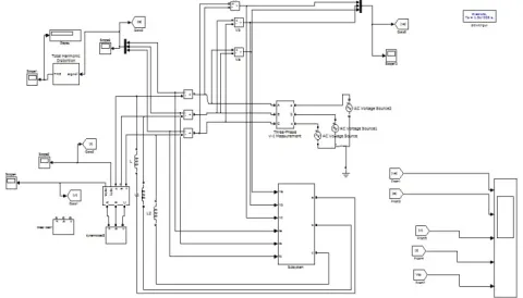
The developed model of three-phase DSTATCOM system and the proposed control scheme in the MATLAB/ SIMULINK environment is shown in Fig. 3 and Fig.4. The performance of DSTATCOM is evaluated in terms of voltage regulation, load balancing and power-factor correction under different load conditions. The load under consideration is a combination of balanced linear lagging power factor loads and a three-phase dynamic load. The unbalance has been created by opening the circuit breaker of phase ‘b’. The performance of the proposed control scheme of three-phase three-wire DSTATCOM is evaluated for sinusoidal supply voltages as well as distorted supply mains.
Fig.3 MATLAB model of DSTATCOM Controller
Fig. 4: Load Consider
12.1 Performance of DSTATCOM for Dynamic load balancing
The DSTATCOM was put into operation at 0.5 sec. At t=0.3 sec the load is changed from three phase to two phase to make the load unbalanced. The DSTATCOM compensates for the unbalanced load and source currents are still balanced and in phase with the source voltages. It is also observed from Fig.5 that during unbalanced load operation, the dc voltage increases and settles to its previous steady state value, once load is balanced.
In order to show the response of DSTATCOM for load balancing, when load under consideration is a combination of a three-phase diode bridge rectifier with resistive load on dc side. It is observed that the supply currents are balanced, sinusoidal and in-phase with the voltages as is shown in Fig.5.
Fig.5Performance of DSTATCOM for dynamic load balancing
13. Conclusion
In this paper authors presents a dynamic load balancing scheme by using D-STATCOM. For this purpose power locked loop based unit template technique is adopted. A result shows the comparison between voltage and currents with and without D-STATCOM. Results show that by using DSTATCOM all three phases are same for voltage and currents.
References
[1] Bhim Singh, Alka Adya, A.P. Mittal & J.R.P Gupta. “Power Quality Enhancement with DSTATCOM for Small Isolated Alternator feeding Distribution System,” IEEE PEDS 2005.
0.7 0.71 0.72 0.73 0.74 0.75 0.76 0.77 0.78 0.79 0.8 -1000
0 1000
Vs
0.7 0.71 0.72 0.73 0.74 0.75 0.76 0.77 0.78 0.79 0.8 -20
0 20
Is
0.5 0.51 0.52 0.53 0.54 0.55 0.56 0.57 0.58 0.59 0.6 -1000
0 1000
VL
0.5 0.51 0.52 0.53 0.54 0.55 0.56 0.57 0.58 0.59 0.6 -20
0 20
IL
0.5 0.52 0.54 0.56 0.58 0.6 0.62 0.64 0.66 0.68 0.7 0
500 1000
Time
Vd
ISSN 2348 – 7968
245 [2] Yash Pal, A.Swarup & Bhim Singh, ’’ A Review of Compensating
Type Custom Power Devices for Power Quality Improvement,” Annual IEEE India Conference (INDICON) ,2010.
[3] Bhim Singh and Jitendra Solanki,” An Improved Control Approach for DSTATCOM with Distorted and Unbalanced AC Mains,” JPE 8-2-3
[4] P. Jayaprakash, Bhim Singh & D. P. Kothari,Ambrish Chandra and Kamal-Al-Haddad,” Control of Reduced Rating Dynamic Voltage Restorer with Battery Energy Storage System,”IEEE,2010. [5] Bhim Singh and Jitendra Solanki,” A Comparison of Control
Algorithms for DSTATCOM,” IEEE Transactions On Industrial Electronics, VOL. 56, NO. 7, JULY 2009.
[6] Anshuman Shukla, Arindam Ghosh, and Avinash Joshi “Static Shunt and Series Compensations of an SMIB System Using Flying Capacitor Multilevel Inverter,” IEEE TRANSACTIONS ON POWER DELIVERY, VOL. 20, NO. 4, OCTOBER 2005.
[7] Anshuman Shukla, Arindam Ghosh, and Avinash Joshi “State Feedback Control of Multilevel Inverters for DSTATCOM Applications,”IEEE TRANSACTIONS ON POWER DELIVERY, VOL. 22, NO. 4, OCTOBER 2007.
[8] Anshuman Shukla, Arindam Ghosh, and Avinash Joshi “Hysteresis Current Control Operation of Flying Capacitor Multilevel Inverter and its Application in Shunt Compensation of Distribution Systems,“IEEE Transactions on Power Delivery, VOL. 22, NO. 1, JANUARY 2007.
[9] N.G.Hingorani and L.Gyugyi, “Understanding FACTS,” EEE
Press, Delhi, 2001.
[10] A.Ghosh and G.Ledwich, “Power Quality Enhancement Using Custom balancing Power Devices,” Kluwer Academic Publishers, London, 2002.
[11] B.N.Singh, A. Chandra and K. Al-Haddad, "DSP based indirect-current controlled STATCOM -1 Evaluation of indirect-current controlled techniques," IEE Proc. on Electric Power Applications, Vol. 147-2, March 2000, VII. pp. 107-112.
[12] Bhim Singh, P. Jayaprakash & D.P. Kothari,” New control approach for capacitor supported DSTATCOM in three-phase fourwire distribution system under non-ideal supply voltage conditions based onsynchronous reference frame theory,” 33 (2011) 1 109–1117 Received 13 February 2008 Accepted 5 December 2010Available online 12 March 2011.