PV Based Grid Connected System Based On
QZSI System
P. S. Bahirat1, U. B. Markad 2, S. A. Patil3, U. A. Chatte4
UG Students Dept. of EE, S. B. Patil College Engineering College, Indapur, Maharashtra, India1-3
Assistant Professor, Dept. of EE, S. B. Patil College Engineering College, Indapur, Maharashtra, India4
ABSTRACT: The quasi-Z-source inverter (QZSI) which originated from the Z-source inverter (ZSI) topology provides an alternative for the conventional two stages DC-DC/DC-AC PV based inverter system with less component number, simpler topology and overcomes some of the limitations and problem associated with the conventional inverter topology. In the application of grid-connected PV inverter system, power storage becomes a critical requirement as a backup to fulfill the power demand. In this context, the QZSI topology has the advantage of easy connection with the storage element with a very minimal modification. This paper presents the grid-connected PV inverter system based on the QZSI topology with a storage capability. The main elements required for the system; the MPPT, dc-link and current control, and the energy storage are detailed plus the analysis of the circuit operation. The simulation results demonstrate the system able to work accordingly.
KEYWORDS:quasi-Z source, grid-connected, PV inverter; battery storage.
I.INTRODUCTION
The use of photovoltaic (PV) energy as an alternative to generate electricity has becomes significant in the recent years. A PV inverter is widely used to convert the photovoltaic energy into usable electrical energy as most of the demands
are in the AC voltage, either for local loads or supplied into the grid. This in general requires an application of two stages conversion as shown in Fig.1; the DC-DC conversion stage to regulate the output voltage from the PV array to
certain required level, and the DC-AC conversion stage to produce the usable sinusoidal AC voltage. The mentioned conventional PV inverter topology however has several drawbacks such as the two conversion stages which lead to
more losses, noise and distortion; complexity in control and additional components that cause the cost to increase.
Fig:-1 PV based grid-connected inverter system
harvested from the PV array cannot fulfill the required demand. Considering the unique topology it has, the QZSI is able to have the storage element connected with a very minimal modification.
In this paper QZSI with continuous current input is applied PV power generation system, and a grid-connected pv system using QZSI is presented. Also QZSI works is presented based on the elaborate analysis and active current and reactive current decoupling control and improved PWM are suggested toss meet the great requirement.
II. LITERATURE SURVEY
Fang Zheng Peng [1], Shows Z-Source Inverter for fuel-cell applications. Through the example, the paper described the operating principle, analyzed the circuit characteristics, and demonstrated its concept and superiority. Analytical, simulation, and experimental results have been presented. The Z-Source Inverter can boost–buck voltage, minimizes component count, increase efficiency, and reduce cost. It should be noted again that the Z-source concept can be applied to the entire spectrum of power conversion. Based on the concept, it is apparent that many Z-source conversion circuits can be derived.
Yuan Li, Joel Anderson, Fang Z. Peng and Dichen Liu [2] presents a quasi-Z-Source Inverter (QZSI)that is a new topology derived from the traditional Z-Source Inverter(ZSI). The QZSI inherits all the advantages of the ZSI, which can realize buck/boost, inversion and power conditioning in a single stage with improved reliability. In addition, the proposed qZSI has the unique advantages of lower component ratings and constant dc current from the source. All of the boost control methods that have been developed for the ZSI can be used by the QZSI. The QZSI features a wide range of voltage gain which is suitable for applications in Photovoltaic (PV) systems due to the fact that the PV cell’s output varies widely with temperature and solar irradiation. Theoretical analysis of voltage boost, control methods and a system design guide for the QZSI in PV systems are investigated in this paper. A prototype has been built in the laboratory. Both simulations and experiments are presented to verify the proposed concept and theoretical analysis. Silver Ott, Indrek Roast, Dmitri Vinnikov [3],describes comparison of Voltage Gain and Voltage Stress of quasi-Impedance Source Inverter under\ given boost factor by using simple-, maximum-boost and maximum constant boost control methods. For each method modulation index, boost factor, voltage gain, shoot-through duty ratio and voltage stress across the switches are expressed and the relationships between them are analyzed. The presented relations will be confirmed in simulations. The three major pulse width modulation control methods for QZSI have been reviewed and compared under the same input voltage and boost factor. The comparison results show that the maximum constant boost PWM method is the most suitable method for QZSI as it has the lowest requirements to the passive components and almost as small voltage stress as the maximum boost control.
III. ANALYSIS OF CIRCUIT OPERATION
There are two states of operation in the conventional voltage source inverter (VSI); the active states when a non zero voltage exists across the bridges and the zero states when either all upper and lower transistors are in ON or OFF condition (Q1Q3Q5/Q4Q6Q2 = 000 or 111) to produce a zero voltage condition across the bridges. In the QZSI, a shoot through condition (short circuit) is purposely introduced during the zero states. The following Fig. 2 shows the equivalent circuit of the QZSI during the shoot-through and the non-shoot-through states. When the QZSI is in a shoot through condition for a duration of T0 from switching cycle of T, based on the circuit diagram of Fig. 2(a), the following equations can be defined.
Then when the QZSI is in an active states condition for duration of T1 from switching cycle of T, the following
Fig 2(a):- shoot through
Fig 2(b):- QZSI during non-shoot through state
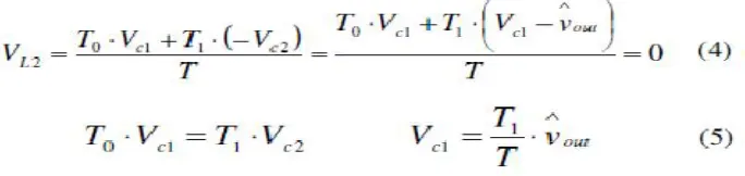
From the above (1), (2) and (3), for the whole one switching period of T, assuming the average voltage across the inductor L2, VL2 is zero in steady state, the following equations can be defined.
Same for the average voltage across the L1, VL1 over one switching period can be defined as follow.
Based on equations (5), (6) and (7), next the following is defined.
Then the average dc-link voltage across the inverter bridges can be found as follow.
Lastly, from (5), (8) and (9), the average voltage across the bridges can be defined as follow.
Defining shoot-through duty ratio D = T0/T and T0 + T1 = T, the following is obtained.
It can be shown that by varying the shoot through time over one switching cycle, the input voltage can be boosted accordingly. As for the case the input voltage comes from the output of PV arrays (Vin = Vpv), from equation (11), if the capacitor voltage Vc1 can be controlled to be constant, the input voltage Vpv increases when the shoot-through time is decreased, and decreases when the shoot-through time is increased as in equation (12).
IV. SYSTEM DESIGN
In the PV based grid connected inverter system, the multipoint power tracking (MPPT), DC link voltage and current control and the battery storage connection are the main component to be designed and configured. The following subsections detail each of the components involved.
A. SYSTEM SPECIFICATION
Table I shows the specification used in the design of PV based QZSI system. The source of the system is the PV array with the maximum power of 5 kW. The voltage of the PV array terminal is boosted by the impedance network of L1, L2, C1 and C2 to produce average 800V across the inverter input. The inverter then produces the sinusoidal current to be supplied to the grid and the synchronization is made through the phase locked-loop (PLL) block.
B. MPPT
The MPPT method to be used is based on the modified perturbed and observed (P&O) method considering its simple algorithm which is widely used. Based on the equation (12), it is known that while regulating the capacitor voltage Vc1 constantly, the optimal voltage for the PV array Vpv = Vmpp which result in maximum power can be obtained by adjusting the shoot-through duty ratio value D appropriately. The value of D is adjusted based on the algorithm in Fig. 5 and used in the form of modulation index m = 1 – D over the carrier signal which determine how long the gates are short-circuited during each cycle.
C. DESIGN OF IMPEDANCE NETWORK COMPONENTS
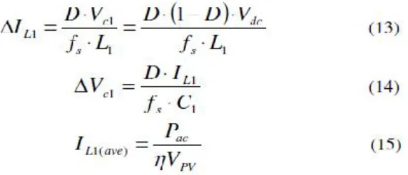
The values of two capacitors (C1 & C2) and two inductors (L1 & L2) at the impedance network are based on the required voltage and current ripple. The following equations (13) to (15) are used to determine the appropriate values [8].
where D : shoot-through duty ratio, fs : switching frequency, Vdc : dc link voltage across the bridges, Pac : AC power to the grid, _ : power efficiency, Vpv : output voltage of PV array.
D. VOLTAGE AND CURRENT CONTROL
The purpose of the voltage control is to have the value across the capacitor and average dc-link voltage across the bridges constant at the required value. The required value of voltage across the bridge Vdc which is equal to Vout in equation (9) can be defined as follow.
V. SUMMARY
In this paper we can conclude that the QZSI is much better system than the conventional inverter. Because we used new advance technology in this paper. QZSI has many advantage compare to conventional inverter. It is one stage operational system. A new method of battery storage connection has been proposed. Hardware implementation and critical power quality at the grid-connection point will be carried out in future works.
REFERENCES
[1] Zulhani Rasin, M.F. Rahman, “Design and Simulation Of QZS Grid Connected PV Inverter Wit Battery Storage” 2012 IEEE IC on power and energy, 2.5 December 2012, Malaysia .
[2] Jie Lui, Fei Wu, “Photovoltiac Grid-Connected System based On QZSI System” Volume7. Number7, April 2013
[3] C.Dinakaran, Abhimanyu Bhimarjun Panthee, Prof. K. Eswaramma, “Modeling & control qzsi For Advanced Power Conditioning of Renewable Energy System” Vol.3 Special Issue 2, April 2014.
[4] D. Umarani and Dr.R.Seyezhai, “A Comparative Study Of Conventional and QZSI Multilevel Inverter For PV applications,”ELELIJ Vol.4, NO 2, May 2015.