Automated Fare Collection System Using
Arm
Dr.T.C.Thanuja1, Vakare Suman R.2
Professor, Dept. of VLSI Design and Embedded Systems, VTU, Belagavi, Karnataka, India1
PG Student, Dept. of VLSI Design and Embedded Systems, VTU, Belagavi, Karnataka, India 2
ABSTRACT:Digitization and cashless economy both have become the need of the hour. Thus it becomes mandatory to develop substitute technologies for the existing ticketing system to keep it in track with the state of the art technologies of developed countries like USA, Japan etc. Also the projects like “Digital India” majorly motivated to design the proposed AFC system. Many substitutes are available to make the ticketing system automated viz. SMS based ticketing, smart phone based ticketing, token based ticketing and etc. All these automate ticketing systems have their own advantages and disadvantages. The AFC system is an automated ticketing system which is based on RFID technology. The system is designed using the controller ARM 2148.When it comes to public transport passenger security is the major matter of concern. Thus this proposed system also has provisions so that the respective authorities can be informed about any such problems happening in the public transport .It uses a GSM module to communicate with the respective authorities. Women security has been a major concern, hence a special panic key is provided which can inform the respective authorities in no time and the passenger could get the necessary help.
KEYWORDS: AFC (Automated Fare Collection), SMS (Short Message Service), RFID (Radio Frequency Identification), GSM (Global System for Mobile communication)
I. INTRODUCTION
The existing fare collection system for public transport buses in India uses a handy machine which dispenses a paper ticket when the bus conductor enters the information regarding the location of the source and destination. Based on the distance from source to destination an amount of fare appears on the paper ticket which has to be paid by the passenger. This particular system has many disadvantages, one of the major drawback is cash transaction which ultimately creates many other problems like unavailability of change. Another problem with the present system is no track of customer information is maintained, thus for a more populated country like India it becomes an issue of major insecurity. Also there are no provisions for women security especially when the bus is roomy. Thus this paper proposes an AFC system which would probably help to solve these basic issues with the present fare collection system for public transport system.
Automated fare collection system automates the conventional ticketing by replacing the cash with contactless IC’s, Smart phones, tokens etc. The AFC system discussed in this paper makes use of RFID technology. Though Smart phones are the emerging option but not a major population of India makes use of them. Thus it becomes important to come up with a substitute which is easy accessible to the passengers.
II. LITERATURE SURVEY
Various approaches are available for making ticketing system automated one of which is smart phone based where in which a mobile phone is used as a ticket, the phone to be used is needed to have either a post-paid or prepaid subscription [2]. Another approach for the ticketing system is the SMS based ticketing where the passenger can book the ticketing with the help of a SMS and also gets the further details of the travel via.SMS [3].Automated ticketing system with personalised navigation helps the travellers to get the navigation information, it uses RFID based electronic infrastructure along with personalised location sensors [4].One of the approaches of automated ticketing make use of IR sensor to keep the tract of passenger count also it uses GPS and GSM to get accident information[5].
GPS based AFC using RFID uses GPS for tracking and surveillance [6].
III. DESIGNING OF AFC SYSTEM
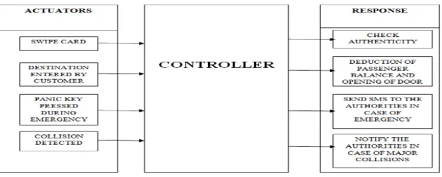
The AFC system design includes three parts actuator, controller and responses- actuators: give inputs to the controller;
controller: controls the performance of the system and responds according to the signals received from actuators;
response: overall output of the system for respective actuations.
The actuator part includes the swiping of the RFID card, then the destination is entered by the passenger and the destination no. acts as an input to the controller, panic key which sends the signals to the controller for further processing and last actuator of the system is a collision detector if detected it will send the input to controller and controller decides whether the further process has to be conducted or not.
The controller part of the system takes the inputs from the actuators processes them to give the desired output responses for every actuation.
Response is the third part of system which generates the actions for respective actuations with the help of the controller. When the first actuation i.e. card swipe is received by the controller it checks, whether the swiped card is valid or not and only valid cards go to the next actuation of entering the destination. After this based upon the destination entered the balance has to be deducted, the respective balance amount for each destination is store in the controller, also the motor responds when this actuation of entering the destination is received by the controller. Other part of the system is the security section when panic key is pressed or collision is detected then the action taken by the system that SMS will be sent to the authorities to a mobile no. which is stored in the controller along with the commands needed to do so.
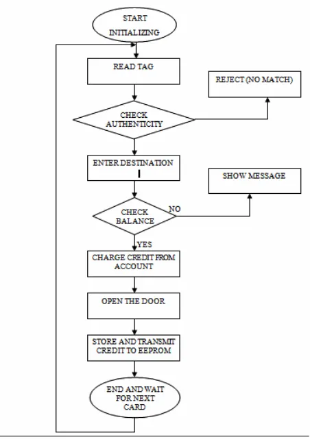
Process flow of the system is explained using a flow chart shown in Figure 2. The actions performed are as follows -
Initializing the system
Read the swiped RFID card.
Check for the authenticity of the card, if valid continued with the process otherwise reject the card and wait for next one.
Ask the passenger to enter the destination.
Check passengers balance, if low then display an alert message on LCD.
Deduct the fare amount from passengers account.
Open the door.
Store the balance in EEPROM
End and wait for next card swipe.
Figure 2 AFC system flow chart
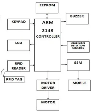
Figure 3 Implementation block diagram
RFID Reader: RFID uses electromagnetic fields to track as well as identify the objects. The RFID tag contains a chip and an antenna. The chip contains electronically stored information. The UIC number, for each individual cards are obtained by connecting the RFID module to the PC using the RS 232 cable. The UIC numbers for the swiped cards can be viewed using the flash magic terminal.
KEYPAD: The keypad used in the proposed system is a4x4 matrix keypad. It is used to enter the destination in this system. The 16th key of the keypad is assigned to other applications like panic button and safety key during collisions whereas the remaining 15 keys are used to enter destination.
LCD: A 16x2 LCD is used, it is programmed using the commands and instructions of LCD interfacing. All the details along the instructions to be followed by the customer are displayed on the LCD.
MOTOR: A D.C. motor is used to provide the movement for opening and closing of door. This DC motor is driven by L293D driver. The motor is programmed in such a way that the doors don’t open until and unless the card is swiped and the amount is deducted, so that without ticket travelling can be obstructed.
GSM MODULE: The main role of GSM modem is to communicate externally via. SMS. There are basically three conditions during which GSM modem communicates externally.
1. When the card is swiped and it matches the pre-stored data, a message of the deducted amount is sent on the registered mobile no. of respective customer.
2. When the collision detection sensors detect a major accident, in that situation it is important to notify the authorities in order to get instant help.
3. When the panic key is pressed it is assumed that the passenger is in danger and needs instant help so, a message ‘passenger is insecure’ is sent.
IV. RESULTS
The results of the AFC system are discussed in two parts initialization and performance evaluation. Performance evaluation is done to verify the results of the following:
Replacing the cash with RFID cards.
Obstructing without ticket travelling.
Collision detection sensor to get information about accidents.
Panic key for women security.
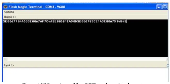
a) Initialization of RFID module and GSM module:
RFID reader testing result obtained using flash magic terminal.
As explained under the RFID title of design and methodology, the UIC of all five cards are fetched using flash magic terminal. The first 12 characters in the string shown in figure 4 is the UIC number for card 1 next 12 for card 2 and so on. UIC number is needed to eliminate the fake cards.
Figure 4 UIC numbers of five RFID cards used in the system.
The UIC numbers fetched from each card is shown in the table below.
Table 1 Respective UIC for RFID cards.
GSM module testing and obtained results on putty terminal.
Figure 5 Response of GSM module to AT commands.
b) Performance evaluation:
Replacing the cash with RFID cards. .
The RFID reader detects all five sample cards which act as cash, with the help of controller it identifies the user name for each card which further gets displayed on the LCD shown in figure 6. Also the authenticity of every card swiped is checked and the invalid or fake cards are discarded as shown in figure 7.
Figure 6 LCD displaying customer name and instruction Figure 7 Output for invalid card
Obstructing without ticket travelling.
Figure 8 Balance displayed Figure 9 Alert message displayed during of low balance
Figure 10 Message received for remaining balance
Panic key for women security.
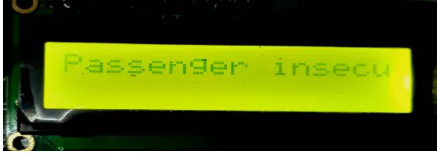
The panic button is used for the security of the passengers and particularly for women security, as soon as this key is pressed it sends a message called “Passenger Insecure” using GSM module. The message also gets displayed on the LCD shown in figure 11.
Figure 11 Output after panic key is pressed
Collision detection sensor to get information about accidents.
Figure 12 System asking the driver about safety after collision Figure 13 When driver fails to press the safety key.
Figure 14 Messages received in case of collision and if panic key is pressed.
V. CONCLUSION AND FUTURE SCOPE
Using the proposed system the ticketing system can be made completely automated and hence ultimately the objectives of making public transport cashless, digital, safe less and reducing the man power can be achieved. Thus it can be concluded with respect to the result obtained that the proposed prototype of the AFC system can be a better substitute to the conventional one and play a vital role in projects like “Digital India” and in making Indian economy cashless. The proposed system can be further modified on different levels of designing and implementation. Many more facilities to make the public transport using AFC more user friendly can be added. In practical implementation the EEPROM can be replaced with a dedicated server so that the AFC system can store details of the customer on large scale. Also the need of power supply can be eliminated by using solar energy which would be an eco-friendly approach to fulfil the power requirements.
REFERENCES
[1] Md. Foisal Mahedi Hasan, Golam Tangim, Md. Kafiul Islam, Md. Rezwanul Haque Khandokar, ArifUl Alam “RFID-based Ticketing for Public Transport System: Perspective Megacity Dhaka”IEEE, , Volume: 6 Pages: 459 - 462, DOI: 10.1109/ICCSIT.2010.5564067, Year: 2010. [2] Deka Ganesh Chandra, Ravi Prakash ,Swati Lamdharia “Mobile Ticketing System for Automatic Fare Collection Model for Public Transport” ,5th International Conference on Computational Intelligence and Communication Networks. Pages: 600 - 603, 2013.
[3] Mohammed Bilal R. Khan ,Sushil Mourya ,Mrs. Sukruti Kaulgud “SMS ticketing system for local trains: A green alternative” International Conference & Workshop on Electronics & Telecommunication Engineering (ICWET 2016) Pages: 1 - 5,2016.
[4]Ana Aguiar, Francisco Maria Cruz Nunes , Manuel João Fernandes Silva, Paula Alexandra Silva, Dirk Elias “Leveraging Electronic Ticketing to Provide Personalized Navigation in a Public Transport Network” IEEE Transactions on Intelligent Transportation Systems., Volume: 13, Issue: 1 Pages: 213 - 220,Year: 2012.
[5] T.Manikandan, G.Kalaiyarasi, K.Priyadharshini, R.Priyanga “Conductor less Bus Ticketing System Using RFID and Accident Information through GPS and GSM” IJISET - International Journal of Innovative Science, Engineering & Technology, Vol. 2 Issue 9, September 2015.