Testing Radio Network Controller (RNC)
Userplane Using Wireshark Tool
Ranjith .s1, Sisil John2, Prakash Geol3, M.B. Kamakshi4
M.Tech Student, Dept. of T.E, R.V. College of Engineering, Bangalore, Karnataka, India1
Expert Engineer, Nokia, Bangalore, Karnataka, India2
Line manager, Nokia, Bangalore, Karnataka, India3
Professor, Dept. of T.E, R.V. College of Engineering, Bangalore, Karnataka, India4
ABSTRACT: The telecommunication domain is developing very rapidly to meet the demand of day to day increase in data rate need. For example initially UMTS data rate was up-to 2 Mbps now it increased to 48 Mbps. This directly implies that the features that are developed are also increasing very rapidly. This increase in data can again degrade the network performance. These new features have to be tested accurately before releasing them on to the real world. In this paper we propose a simple and easy method to test RNC UserPlane functionality using wireshark tool. Functionalities imply that the RNC is working as per the standards. In other words user data which RNC receives should not be dropped due to RNC (or within some tolerance). This project is carried out at Nokia.
KEYWORDS: Userplane, wireshark, RNC
I. INTRODUCTION
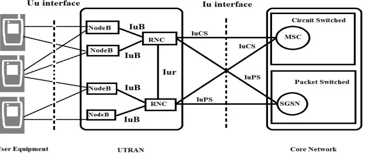
Universal Mobile Telecommunication system (UMTS), widely known as 3G network is standardized by 3GPP (Third Generation Partnership Project). The UMTS can be divided into three parts as shown in figure 1, this contains User equipment (U.E.), Radio access Network and core network (C.N.).
Figure 1: UMTS architecture
C.N. will instruct the RNC to allocate radio resource as per the service type in terms of QoS parameters. The core network is again split in to two domains one for Circuit switch domain which handles voice calls and other for packet switched domain which carries Data traffic i.e. IP network. The radio access scheme used in UMTS is Wideband Code Division Multiple Access (WCDMA) which is been defined by Third Generation Partnership Project (3GPP). In this scheme a user can use the channel for the entire time and frequency but the users are separated with respect to codes which are orthogonal to each other.
The UMTS network entities are connected by different interfaces as shown in the figure 1. The U.E. connects to UTRAN that is Access network through Uu interface. Uu interface is WCDMA air interface which supports both Frequency Division Duplexing and Time Division Duplexing scheme. The U.E directly interfaces with NodeB. The NodeB acts as relay between U.E. and RNC. The NodeB and RNC are interconnected through IuB interface [3]. The RNC controls Multiple NodeBs through IuB interface. The two RNC are logically interfaced through Iur interface which enables soft handovers. The RNC interfaces with Core Network using Iu interface. This Iu interface again has two logical interface’s IuPS and IuCS [5]. IuPS interface is for packet switch data; this connects with Packet switch domain of core network i.e. to Serving GPRS Support Node (SGSN). IuCS is for circuit switched data; this connects with circuit switch domain of core network i.e. to Mobile Switching Center (MSC).
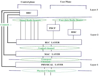
Figure 2: UMTS general Radio interface protocol architecture
II. LITEARTURE SURVEY
PDCP and BMC belong to User plane protocol, whereas RLC and MAC belong to both User plane as well as Control plane as shown in the figure 2. Protocol will offer services to its higher layers via the Service Access Point (SAP).
A. RRC protocol:
RRC protocol is a Layer 3 control plane protocol which controls RLC, MAC, PDCP, BMC and Physical layer protocol [2]. This is used to configure layer 1 and layer 2 resources as part of Radio Resource Management function. This protocol carries out the connection management procedures. One such procedure is RRC connection establishment procedure. There exists one RRC connection between U.E. and UTRAN. U.E initiates RRC connection establishment procedure by sending a RRC Connection Request message when:
a. NAS layer request on U.E or UE has some data to send
b. Paging from UTRAN i.e. if there is incoming call
c. Signaling is required with Core Network.
As a result a signaling connection is formed as a combination of an RRC connection between U.E. and UTRAN and Iu connection between UTRAN and Core Network. This RRC connection creates signaling radio bearers (SRB) to carry RRC signaling information. SRB are also used to set up and configuring Radio Bearer (RB) carrier User Data between UE and UTRAN. In general Radio bearer are the Service Access Points (SAP) offered by Layer 2 to higher layer. Radio bearer’s define configuration for Layer 2 and Physical Layer in order to meet the QoS for particular service. Iu bearer are setup between Core Network and UTRAN. The Radio bearer and Iu bearer together form Radio access bearers (RAB) [4] these are again setup by SRBs.
B. Wireshark tool:
Wireshark is a GUI network protocol analyzer. A network packet analyzer is used to capture network packets and displays the packet with detailed protocol information. Wireshark tool can be used for debugging purposes. In this project wireshark is used for capturing data during the call, captured data is used to find data or packets are droped due to RNC. Since wireshark tool is a GUI based network sniffer it cannot be used for automatic analysis. Wireshark provides command line interface (CLI) feature to filter and capture the data on the network. Tshark can be used as a command line interface to filter data whereas Dumpcap provides a command line interface to capture packet data on network. Tshark is a terminal oriented version or command line interface of Wireshark designed for capturing packets over the network.
III. IMPLEMENTATION WIRESHARK ANALYSIS FOR TESTING RNC
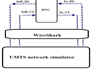
The setup is as shown in the figure 3, since the system under test is RNC only the RNC is real entity and rest of UMTS network including the calls are simulated using a Performance Tester (PET) which is Nokia proprietary tool. The wireshark tool is installed onto a remote machine which is kept in between RNC and the simulator which is as
Figure 3: Wireshark Setup for testing RNC Layer 2
The step involved in detecting data drops are as follows.
i. Start Wireshark collection
ii. Start the Calls
iii. Wait till the call duration
iv. Stop log collection
v. Extraction of required call information from the wireshark Dump (PCAP file)
vi. From call specific information extract interface level data.
vii. Throughput is calculated and Validated
A. Wireshark collection:
During call establishment RABS are created between U.E. and Core Network, which is the combination of Radio bearers and Iu bearers. During call establishment socket ports for RBs, SRBs, and IuPS/IuCS are created. In order to test the RNC data drops at RNC are checked, throughput on IuB interface and Iu interface are compared against each other. In other words data entering RNC should equal or approximately equal to data leaving RNC.
In order to do this evaluation the data on the network has to captured/collected using a network analysis. In this project wireshark is used. RB channel carries user data and SRB carries signaling data. Wireshark captures all the packets that are flowing from NodeB to RNC i.e. packets that are flowing on IuB interface and RNC to Core network i.e. packets that are flowing on IuPS/CS interface. The captured packets are written into PCAP (Packet Capture) file, which is a binary file. This file can be opened in human readable format using wireshark tool as shown in figure 4 below.
Figure: 4 Wireshark GUI
Dumpcap is used to capture data packet flowing between RNC and simulator. The command is given (eq 1) dumpcap -i interface -b filesize: filesize -w FILE_NAME ………..[1]
The equation has three arguments
a) First argument is the interface on which the data has to be captured
b) Second argument is the maximum size of the file
c) Third argument is the name of the file to which the captured data has be written
B. WireShark analysis.
tshark command = 'tshark -r file.pcap -Y "udp.srcport == 1532 || udp.dstport == 1532 || udp.dstport == 1664 || udp.dstport == 1665 || udp.dstport == 65535 || udp.dstport == 1531||udp.srcport == 1664 || udp.srcport == 1665 || udp.srcport == 65535 || udp.srcport == 1531|| gtp.teid == 0x00000001||gtp.teid == 0xBED0000A" -w
000000000000000.pcap' ………..[2] As mentioned earlier, for each call a set of ports are assigned for IuB and Iu interface assigned by RNC, based on these port numbers the calls can be separated. This is achieved using Tshark, where the packets corresponding to a particular call or mobile can be filtered. After this a Pcap that is specific to a particular call will be created. The Tshark has feature to exact data based on the port as given by the equation 1. Output is dumped into a PCAP file which is specific to particular call. From this Pcap file the data on IuB Downlink and Uplink, data for IuPS/CS Downlink and Uplink are separated.
a) The equation for filtering [2] has three arguments.
b) Tshark is the executable, which filters input Pcap file to generate Call specific data.
c) First argument is the file name to read, -r instructs read operation to Tshark.
d) Second argument contains port numbers to be filtered
e) Third argument is output file were the filtered data has to be dumped
After this step four Pcap files are generated. Since these files are in binary format, this file is converted into readable text format. This is achieved using Tshark command line interface as given in the equation 3. Instead converting the binary file into text format, the Tshark has a feature which provides number of frames or bytes that were captured in the PCAP file.
tshark -r IUB_UL.pcap -z io,stat,[interval] -q > IUB_UL.csv ………[3] The above equation has four part
a) First is the Tshark which is the executable which converts Pcap file into Readable format
b) Second –r .PCAP file which is the input file
c) Third part ,–z io,stat,[interval], gives the statics, i.e. number of frames and bytes collected in the interval mentioned. For example if interval is set to 1 then it generates statics for every one second.
d) Fourth part is output file to which the statics of a link has to be dumped, the output file is as shown in figure
5.
Figure: 5 I O Statics
IV. CONCLUSION
The method presented to detect packet drops is very simple and easy to implement. Hence the first level of inference can be made weather the packets drops are due to RNC. If in case the failure was detected, then RNC with respect to the protocol level has to be debugged.
REFERENCES
1. 3GPP TS 23.110: "UMTS Access Stratum; Services and Functions".
2. 3GPP TS 25.331: "RRC Protocol Specification".
3. 3GPP TS 25.430: "UTRAN Iub Interface: General Aspects and Principles".
4. 3GPP TR 25.993: "Typical examples of Radio Access Bearers (RABs) and Radio Bearers (RBs) supported by Universal Terrestrial Radio Access (UTRA) ".
5. 3GPP TS 25.410: "UTRAN Iu Interface: General Aspects and Principles".