ISSN (Print) : 2320 – 3765 ISSN (Online): 2278 – 8875
I
nternational
J
ournal of
A
dvanced
R
esearch in
E
lectrical,
E
lectronics and
I
nstrumentation
E
ngineering
(An ISO 3297: 2007 Certified Organization) Website: www.ijareeie.com
Vol. 6, Issue 3, March 2017
Machine to Machine Communications for
Industry Management System in Smart Grid
T. Selvaraj1, S. Shajin2, K.Chithra3
UG Students, Department of Electronics and Instrumentation Engineering, PSN College of Engineering and
Technology, Tirunelveli, Tamilnadu, India1, 2
Assistant Professor, Department of Electronics and Instrumentation Engineering, PSN College of Engineering and
Technology, Tirunelveli, Tamilnadu, India3
ABSTRACT: Here we propose a system that establishes communication between multiple household appliances through power line communication. Normally Power line for houses will supply load current. In this project we are using ZigBee to control devices at home. The isZigBee used to bring the domestic appliances in to the control system. Nowadays major communication networks can be divided into four types, namely: IP Core Network/Internet, Wireless LAN, 3G/4G Cellular Network and Ad-hoc PAN. The common usage for these networks is to carry text, audio and video content. Recently, some of these networks have been utilized in industrial automation to monitor and control industrial plants. Here we have to implement an effective control system to maintain the different loads depending upon the priority. Nowadays, Zigbee applications are gaining ground and it is extending to industrial automation including marine and aircrafts electronics, factories, cars, trucks and many others. The backbone of the Zigbee is a fast serial bus that is designed to provide a reliable, efficient, and a very economical link between sensors and actuators. The domestic appliances can well establish the communication between them through the Zigbee network. Thus resource sharing made simple. The network helps in enabling and disabling the house hold appliances with the specified priority. The high priority device will always have the command over the network. This system effectively helps in resource sharing between different appliances located in different places.
KEYWORDS: ArduinoUno, ZigBee sensor, level sensor, Monitoring, Relay, Relaydriver, Mx232, power supply
I. INTRODUCTION
Condition-based maintenance is a novel scientific maintenance strategy, which decides the optimal maintenance time according to the actual condition of the machinery to prevent unexpected catastrophic faults, improve the reliability and availability of the machinery, decrease downtime, and increase operating efficiency. Condition monitoring techniques are continually evolving to make the best use of the latest technological advances, from the earliest watching, listening, and feeling of skilled engineers, analog instruments, portable data loggers, and analyzers to online wired monitored systems. Currently, online wired monitored systems are successfully employed in many large industrial sites to monitor the critical devices and process parameters.
However, there are still many other noncritical devices that are not regularly monitored. Combining these into the wired monitoring system may significantly increase system cost because of the need for additional cabling. Sometimes, the installation cost may be even higher than the cost of the sensor itself, particularly for remote monitoring. Adding monitors using a wired system is also inconvenient for doing temporary or specialized tests. Wireless sensor networks (WSNs) provide one potential solution to tackle these challenges. Compared with a wired system, WSNs have many inherent advantages, such as relatively low cost, convenience of installation, and ease of relocation. These merits make a low-cost condition monitoring system for noncritical equipment possible.
ISSN (Print) : 2320 – 3765 ISSN (Online): 2278 – 8875
I
nternational
J
ournal of
A
dvanced
R
esearch in
E
lectrical,
E
lectronics and
I
nstrumentation
E
ngineering
(An ISO 3297: 2007 Certified Organization) Website: www.ijareeie.com
Vol. 6, Issue 3, March 2017
monitoring [1], construction health monitoring [2], temperature monitoring in product distribution [3], and debris flow monitoring [4]. However, industrial processes and devices have unique characteristics and make further demands on industrial WSNs (IWSNs), such as processing heterogeneous sensor signals, higher sampling rates, faster data transmission rates, and higher reliability [5], [6]. In addition, compared with wired monitoring systems, WSN monitoring systems have constrained resources, including limited radio bandwidth, computational ability, and battery energy. Therefore, a key question to be addressed in this work is how to achieve these higher system requirements
using resource-constrained IWSNs.
II. EXISTING SYSTEM
This decade is widely predicted to see the rise of Machine-to-Machine (M2M) communications over wired and wireless links. For instance, statistics suggest that, by 2014, there would be 1.5 billion wirelessly connected devices that are not mobile phones and do not require any human intervention. This will lead to an unprecedented increase in the data traffic involving machines communicating with other machines without human interaction.
Today’s network infrastructure, largely based on Synchronous Optical Networking (SONET) and Synchronous Digital Hierarchy (SDH) technologies, cannot physically or economically support the ever-changing demands caused by the overwhelming increase in bandwidth, transport of IP traffic, and the need for more flexible connectivity, higher resiliency, and network automation.
While this work attempted to identify security threats against M2M communications, the exact technologies upon which M2M communications are based were not taken into account.
III. PROPOSED SYSTEM
To facilitate effective SG communication, existing networking technologies must be taken intoaccount to deal with the multiple services and quality requirements of the residential appliances. The need to differentiate high- and low-priority traffic will be just as important as to be able to dynamically adapt the network to varying capacity requirements in real time. Therefore, it is essential that we consider appropriate technologies to implement the communication networks of SG, which may allow the flexible use of existing capacities without impacting the service quality of the SG In this article, we provide a detailed M2M communicationmodel for SG and verify the effectiveness of different adopted communication technologies. This article describes the shortcomings of the conventional networking technologies, which may be adopted for SG M2M communications.
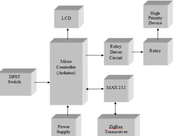
IV. BLOCK DIAGRAM
ISSN (Print) : 2320 – 3765 ISSN (Online): 2278 – 8875
I
nternational
J
ournal of
A
dvanced
R
esearch in
E
lectrical,
E
lectronics and
I
nstrumentation
E
ngineering
(An ISO 3297: 2007 Certified Organization) Website: www.ijareeie.com
Vol. 6, Issue 3, March 2017
Machine2:
Figure :Block diagram for level section Machine 3:
Figure: Block diagram for heating section Hardware
Figure: Arduino
An Arduino board historically consists of an Atmel 8-, 16- or 32-bit AVR microcontroller (although since 2015 other makers' microcontrollers have been used) with complementary components that facilitate programming and incorporation into other circuits. An important aspect of the Arduino is its standard connectors, which lets users
ISSN (Print) : 2320 – 3765 ISSN (Online): 2278 – 8875
I
nternational
J
ournal of
A
dvanced
R
esearch in
E
lectrical,
E
lectronics and
I
nstrumentation
E
ngineering
(An ISO 3297: 2007 Certified Organization) Website: www.ijareeie.com
Vol. 6, Issue 3, March 2017
Figure : Arduino Uno
There are many Arduino-compatible and Arduino-derived boards. Some are functionally equivalent to an Arduino and can be used interchangeably. Many enhance the basic Arduino by adding output drivers, often for use in school-level education to simplify the construction of buggies and small robots. Others are electrically equivalent but change the form factor, sometimes retaining compatibility with shields, sometimes not. Some variants use completely different processors, with varying levels of compatibility.
Software
Arduino Software IDE
Figure :Software IDE
A screenshot of the Arduino IDE showing the "Blink" program, a simple beginner program
A typical Arduino C/C++ sketch consist of two functions that are compiled and linked with a program stub main() into
an executable cyclic executive program:
Setup (): a function that runs once at the start of a program and that can initialize settings.
Loop(): a function called repeatedly until the board powers off.
ISSN (Print) : 2320 – 3765 ISSN (Online): 2278 – 8875
I
nternational
J
ournal of
A
dvanced
R
esearch in
E
lectrical,
E
lectronics and
I
nstrumentation
E
ngineering
(An ISO 3297: 2007 Certified Organization) Website: www.ijareeie.com
Vol. 6, Issue 3, March 2017
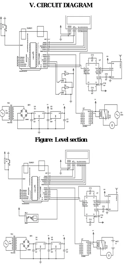
V. CIRCUIT DIAGRAM
Figure: Level section
ISSN (Print) : 2320 – 3765 ISSN (Online): 2278 – 8875
I
nternational
J
ournal of
A
dvanced
R
esearch in
E
lectrical,
E
lectronics and
I
nstrumentation
E
ngineering
(An ISO 3297: 2007 Certified Organization) Website: www.ijareeie.com
Vol. 6, Issue 3, March 2017
Figure: Head section
VI. CIRCUIT EXPLANATION
When AC is applied to the primary winding of the power transformer it can either be stepped down or up depending on the value of DC needed. In our circuit the transformer of 230v/15v is used to perform the step down operation where a 230V AC appears as 15V AC across the secondary winding. In the power supply unit, rectification is normally achieved using a solid-state diode. Diode has the property that will let the electron flow easily in one direction at proper biasing condition. As AC is applied to the diode, electrons only flow when the anode and cathode is negative. Reversing the polarity of voltage will not permit electron flow. A commonly used circuit for supplying large amounts of DC power is the bridge rectifier. A bridge rectifier of four diodes (4*IN4007) is used to achieve full wave rectification. Two diodes will conduct during the negative cycle and the other two will conduct during the positive half cycle. The DC voltage appearing across the output terminals of the bridge rectifier will be somewhat less than 90% of the applied RMS value. Filter circuits, which usually capacitor is acting as a surge arrester always follow the rectifier unit. This capacitor is also called as a decoupling capacitor or a bypassing capacitor, is used not only to ‘short’ the ripple with frequency of 120Hz to ground but also to leave the frequency of the DC to appear at the output. The voltage regulators play an important role in any power supply unit. The primary purpose of a regulator is to aid the rectifier and filter circuit in providing a constant DC voltage to the device. Power supplies without regulators have an inherent problem of changing DC voltage values due to variations in the load or due to fluctuations in the AC liner voltage. With a regulator connected to the DC output, the voltage can be maintained within a close tolerant region of the desired output. The regulators IC7812 and 7805 are used to provide the +12v and +5v to the circuit.
The LCD we have used in this project is HD1234. This is an alphanumeric type of LCD with 16 pins. Of which Pins 7 to 14 are used as data pins, 11 to 14 pins are connected to port D of PIC16F877A microcontroller. There are 3 control
pins RS (Pin-4), RW (Pin-5) and EN (Pin-6). The RS pin is connected to the 29th Pin of micro controller. The RW pin
is usually grounded. The RW is connected to 28th Pin. The EN pin is connected 30th pin. The LCD has two Rows and
16 Columns. The LCD is powered up with 5V supply connected to Pins 1(GND) and 2(Vcc). The Pin 3 is connected to Vcc through a Potentiometer. The potentiometer is used to adjust the contrast level. Here in our project we use the PIC controller in 4-bit mode. Here only 4 data pins are connected and are used as Data Port.
Comparator is often necessary to be able to detect a certain voltage and switch a circuit according to the voltage that has been detected. Here we use LM324 as comparator. This consists of 4 op-amps inbuilt on to it and 14 pins. We can
connect sensors with inverting inputs and potentiometers connected on the Non-inverting inputs. The 4th pin of the
LM324 is Vcc and 11th pin of the LM324 is GND. The 5V supply is given to the Vcc. The output pins are interfaced to
ISSN (Print) : 2320 – 3765 ISSN (Online): 2278 – 8875
I
nternational
J
ournal of
A
dvanced
R
esearch in
E
lectrical,
E
lectronics and
I
nstrumentation
E
ngineering
(An ISO 3297: 2007 Certified Organization) Website: www.ijareeie.com
Vol. 6, Issue 3, March 2017
The relays are connected to microcontroller through ULN2003 relay driver IC. The ULN2003 has 16 pins. The 9th pin
of ULN2003 is Vcc and 8th pin of the ULN2003 is GND. The 12V supply is given to the 9th pin of the ULN2003. The
ULN2003 has 7 input pins (1-7) and 7 output pins (10-16). The ULN consists of Darlington arrays. In both of the section, (Primary and secondary) the relay driver inputs are fed into the port B (port B7 and port B6) of the micro controller.
VII. HARDWARE IMPLEMENTATION
Tabulation
SL.NO MACHINE INPUT OUTPUT
1. Crusher
Load Motor On
No Load Motor Off
2.
Level
Low Motor On
Medium Motor On
High Motor Off
3. Temperature
Normal Switch On
ISSN (Print) : 2320 – 3765 ISSN (Online): 2278 – 8875
I
nternational
J
ournal of
A
dvanced
R
esearch in
E
lectrical,
E
lectronics and
I
nstrumentation
E
ngineering
(An ISO 3297: 2007 Certified Organization) Website: www.ijareeie.com
Vol. 6, Issue 3, March 2017
VIII. CONCLUSION
The project “MACHINE TO MACHINE COMMUNICATION” has been completed successfully and the output results are verified. The results are in line with the expected output. The project has been checked with both software and hardware testing tools. In this work “LCD, Microcontroller and Relay” are chosen are proved to be more appropriate for the intended application. The project is having enough avenues for future enhancement. The project is a prototype model that fulfills all the logical requirements. The project with minimal improvements can be directly applicable for real time applications. Thus the project contributes a significant step forward in the field of “Control System”, and further paves a road path towards faster development s in the same field. The project is further adaptive towards continuous performance and peripheral up gradations. This work can be applied to variety of industrial and commercial applications.
REFERENCES
[1] Wikipedia(hnp:1 len.wikipedia.orgjwiki/blackouts)
[2] DusitNiyato, Lu Xiao,and Ping Wang"Machine-to-Machine Communications for Home Energy Management System in Smart Grid" IEEE Communications Magazine. April 2011.
[3] Zubair Md. Fadlullah, Akira Takeuchi, Noboru Iwasaki, and Yousuke Nozaki "Toward Intelligent Machine-to Machine Communications in Smart Grid" IEEE Communications Magazine, April 2011.
[4] S. Hattangady, "Wireless M2Mthe Opportunityis Here!(Part 1 )," hnp://emblazeworld.coml AnachmentsArticles/2009-May Cellular Whitepaper Part 1.pdf
[5] Rongxing Lu, Xu Li, Xiaohui Liang, and Xuemin (Sherman) Shen "GRS: The Green, Reliability, and Security of Emerging Machine to Machine Communications"IEEE Communication magazine 2011.
[6] J-S. Lee, Y. Su and c-c. Shen, "A Comparative Study of Wireless Protocols: 8luetooth, UWB, Zig8ee, and Wi-Fi,"Proc. 33rd Annual Conf. IEEE Industrial Elect. Soc.,Taipei, Taiwan, Nov. 2007.
[7] Michael Starsinic,”System Architecture Challenges in the Home M2M Network", lnterDigitalCommunications, LLC King of Prussia, PA,201O IEEE.