Available Online atwww.ijcsmc.com
International Journal of Computer Science and Mobile Computing
A Monthly Journal of Computer Science and Information Technology
ISSN 2320–088X
IJCSMC, Vol. 4, Issue. 11, November 2015, pg.153 – 158
RESEARCH ARTICLE
Design of an Efficient FSM for
an Implementation of AMBA
AHB in SD Host Controller
G.S.Arunkumar
1, N.Soundar
2, Mathankumar
31
Assistant Professor (ECE), Sri Eshwar College of Engineering, Coimbatore
2PG Scholar (Applied Electronics), Sri Eshwar College of Engineering, Coimbatore 3Testing engineer and TL, Success Solution, Coimbatore
Abstract—A typical System-on-Chip (SOC) design is having many different cores linked together with complex on chip bus communication architectures. This on-chip bus communication architecture determines how these different functional cores exchange and synchronize their data. AMBA has a hierarchy of buses with Advance high performance bus (AHB) that can be used to get connected to high performance peripherals and APB (Advance Peripheral Bus) that can be connected to low performance peripherals. Hence, among all, AMBA is the most preferable communication architecture. AHB bus is used in high performance and high bandwidth system as it has high performance features, like burst transfer, split transaction and pipelined operation. In AMBA system, AHB master is the main component that initiates the read and writes transactions. This paper focuses on design of finite state machine for the implementation of AHB master in Verilog HDL.
Keywords- AMBA, AHB, APB, AHB Master, SOC, Split transaction.
1. INTRODUCTION
The Advanced Microcontroller Bus Architecture specification is an on-chip communication standard for designing high-performance microcontrollers. A typical System-on-Chip (SOC) design contains many different IP cores linked together with sophisticated on-chip bus communication architectures. This deals with a great impact on the system’s performance. There are many communication architectures used in the industry like AMBA, PI-bus, Core Connect, Wishbone, Avalon etc. AMBA is a standard interface specification which makes sure of the compatibility between different IP components provided by different design vendors.
1.1 Types of Buses
An AMBA based embedded microcontroller typically consists of a high-performance system backbone bus (AMBA AHB or ASB), which is able to maintain the external memory bandwidth. AHB bus provides a high-bandwidth interface between different elements which are involved in the different transfers.
Fig.1 Block Diagram of SD Host controller
There is also an availability of the AHB to APB Bridge, which is used to access low peripheral devices on high performance bus. APB Bridge is only the master for APB bus [2]. This paper mainly deals with AMBA AHB bus and particularly AHB master. The paper is divided into three sections. First section is introduction that introduces AHB system, its features and some signals associated with AHB master. Second section has the description related to finite state machine designed for AHB master. Finally the Third section contains the results of implementing the state machine in the Verilog hardware description language.
1.1.1
.
Advanced high Performance Bus (AHB)
AHB bus is a new generation of AMBA 2.0 specification which is intended to point out the requirements of high-performance synthesizable designs. AHB is the new level of bus which sits above ASB and APB. The features required for high performance, high clock frequency systems are as follows [1]:-
Burst transfers (4/8/16 beat burst)
Split transactions
Bus master handover in single cycle
Single clock edge operation
Wider data bus configuration (8/16/32/64/128/256/512/1024 bits)
Pipelined operation
Fig.2 AHB multiplexer interconnection [1]
1.1.2 AHB Operation
Before starting the AMBA AHB transfer, the bus master must have to be granted access to the bus. In this process first of all master asserts a request signal to an arbiter. Now the arbiter will indicate when the master will get the grant of the bus. This decision of granting the access to bus is achieved using some arbitration mechanism like priority based or round robin mechanism etc. A granted bus master then starts the AHB transfer by first driving an address and control signals.
These address and control signals provide information about an address, direction and width of the transfer, burst transfer information if the transfer forms the part of the burst [1].
There are two different forms of burst transfers that are allowed [1]:-
INCREMENTING: does not wrap at address boundaries
WRAPPING: wrap at address boundaries Every transfer consists of two phases as:-
Address and control cycle phase
Data phase
2. FINITE STATE MACHINE FOR AHB MASTER
Main component in the AMBA system is the master with complex interface that can initiate the read or write transfer to any slave. So it is imperative that master is properly designed for an AHB system to work. In addition AHB master implementation has to support advance features like burst transfers, split transaction, pipelined operation as defined in the specification.
The following section contains the brief description of every state in the diagram.
1) IDLE: FSM of AHB master starts with IDLE state and this is the default state in the state machine. When master has no data to transfer or it has just finished the transaction at that time it will stay in this IDLE state. When master wants to perform an another transaction then it will have to request for a bus to an arbiter so it will move in to BUSREQ state.
2) BUSREQ: (Bus Request) The AHB master will wait in this state until the bus has been granted by an AHB arbiter. Arbiter grants the access to bus using some arbitration mechanism. Once the bus is granted to that particular master then it will move to NSEQRD state for the read transfer or to NSEQWR state for write transfer.
3) NSEQRD: (Non Sequential Read) As we earlier studied that AMBA AHB has the pipelined architecture, so address and control information is sent first in this cycle and based on the control information like burst size (hburst ) and size of transfer (hsize) , next state and address are decided. If the transfer type is a single burst transfer then next state will be RDWAIT for getting data for this address provided by the master in first cycle and if the transfer type is an incrementing burst transfer then the next state will be SEQRD. If in between the grant to the master is lost due to some reason then it will move to LASTRD state for latching data and freeing the bus. In this state, it is a single transfer or a first transfer of a burst so htrans value will be „10‟ which shows non sequential transfer.
4) SEQRD: (Sequential Read) this is a sequential transfer, the value for htrans will be “11” which shows sequential transfer type. The next address will be generated based on the size of the transfer (8/16/32/64 bits etc). AMBA AHB is a byte addressable i.e. each address contains 1 byte.
If the size is byte (8 bits), then previous address will be incremented by 1, if it is half word then previous address will be incremented by 2 and for word the previous address will be incremented by 4. Based on the value of hburst (4/8/16 beat burst), burst complete signal is asserted to show that this is the last transfer on the burst and state is transferred to RDWAIT to latch the final data of the burst. If grant is lost in the middle of the burst due to some reason then state will be transited to LASTRD and then master will re arbitrate for the bus for the completion the remaining burst.
Fig.4 FSM of AHB Master
5) RDWAIT: (Read Wait) The master will be in this state if it is a single transfer or the last transfer of the burst. The final data is latched in this state and if hready = high and OK response is asserted by the slave, it shows that the read transaction has finished successfully on the bus and master can move to IDLE state.
7) NSEQWR: (Non Sequential Write) In this state of FSM, hwrite signal will be 1 to indicate the write transaction from the master. If it is a single burst write transfer then next state will be WRWAIT for transferring data for this address provided by the master and if it is incrementing burst transfer then the next state will be SEQWR. If grant to the master is lost in the middle of the transfer due to some reason then it will move to LASTWR state for writing the last data and freeing bus. In this state, it is a single transfer or a first transfer of a burst, so htrans value will be “10” which shows non sequential transfer.
8) SEQWR: (Sequential Write) This state indicates the sequential transfer, now the value for htrans will be “11” which shows sequential transfer. The next address will be generated based on the size of the transfer (8/16/32/64 bits etc). If the size is byte, then previous address will be incremented by 1, If the size is half word then previous address will be incremented by 2 and if word then previous address will be incremented by 4. Based on the value of hburst (4/8/16 beat burst), the burst complete signal is asserted to show that this is the last transfer on the burst and state is transferred to WRWAIT to write the final data of the burst. If grant is lost in the middle of the burst transfer then state will be transited to LASTWR and then master will re arbitrate for access to bus for the completion of remaining burst.
9) WRWAIT: (Write Wait) Master will be in this state, when it is a single transfer or the last transfer of the burst. The final data is written in this state and if hready = high and OK response is asserted by the slave, indicating that the write transaction has finished successfully on the bus and master can move to the IDLE state.
10) LASTWR: (Last Write) The master will be in this state if it lost the grant of the bus in the middle of the transfer, so in this state it will write the data of the address in the previous cycle due to pipeline operation and then master will re-arbitrate for the bus for the completion of the remaining burst. If in the middle of the transaction, error, split or retry response comes from the slave then master will stop the transaction and move to the IDLE state.
3.
RESULTS AND PERFORMANCE ANALYSIS
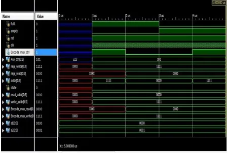
After the completion of this finite state machine, any hardware description language can be used to implement it and checked for functionality correctness. In this Paper, the state machine is implemented in Verilog HDL language and XILINX simulation tool is used to simulate the design and generate the waveforms.
The Figure 5 as shown below indicates single burst write transfer operation with size of the transfer equal to 32 bit. When the request is granted to the master, starts the transaction by giving address and the control information. The value of hburst = 000, indicates single burst transfer and hwrite = 1 indicates write transfer. htrans value is 10 for the transfer indicating non sequential transfer. Hresp = 00, indicates OK response from the slave showing slave is ready to receive data. Hsize = 010 indicating word transfer.
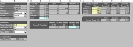
Fig .7 Power analysis of FIFO
Conclusion
The efficient FSM design for AMBA AHB master circuit has been successfully simulated using Xilinx and Modelsim tools. The various parameters are of the circuits are recorded. AMBA master is the main integral part of the system. Hence, designing it with efficient technique will lead to area and timing efficient design of the full system on chip
References
[1] AMBA Specification Rev 2.0. ARM Ltd., 1999.
[2] “AMBA Design Kit revision r3p0”, Technical Reference Manual, ARM Inc.
[3] “AHB Example AMBA System”, Technical Reference Manual, ARM Inc.
[4] Rohit Hardia, Prof.Jai Karan Singh, Prof..Mukesh Tiwari “ Design And Simulation of a typical high performance AHB Reconfigurable Master For On-chip bus Architecture using Verilog HDL”, International Conference on Communication Systems and Network Technologies, IEEE 2011.