An Improved DBF Processor with a Large Receiving Antenna
for Echoes Separation in Spaceborne SAR
Hongbo Mo1, *, Wei Xu2, and Zhimin Zeng1
Abstract—Digital beamforming (DBF) on receive in elevation with a large receiving antenna will be widely adopted in future spaceborne synthetic aperture radar (SAR) missions to improve system performances. Furthermore, DBF can be used to separate echoes corresponding to different sub-pulses in some novel spaceborne SAR imaging modes. This paper proposes an improved DBF processor with a large receiving antenna for separating echoes. The proposed DBF processor includes three important parts: multiples sharp receiving beam generation, range compression and null steering. Compared with the conventional DBF processor in spaceborne SAR, the proposed DBF processor can separate echoes with better performances. Simulation results on point targets demonstrate validity of the proposed DBF processor.
1. INTRODUCTION
Future spaceborne microwave remote sensing missions require synthetic aperture radar (SAR) systems to obtain high resolution wide swath imaging (HRWS) capacity [1–3]. The limitation between azimuth resolution and range swath is well resolved by introducing azimuth multichannel on receive technique. In addition to overcome the limitation, improving signal to noise ratio (SNR) and suppression range ambiguity should also be considered during SAR system design. Digital beamforming (DBF) on receive with a large receiving antenna in elevation in spaceborne SAR can form a sharp high gain scanning beam to receive radar echoes, and this method is named as the SCORE (SCan-On-REceive) technique [4–7]. Afterwards, the desired radar echoes arrive at the receiving antenna with a high antenna gain, while range ambiguities arrive at the receiving antenna with a low antenna gain. Therefore, the DBF on receive method in elevation can be adopted to obviously improve system performances, especially for range ambiguity to signal ratio (RASR) and noise equivalent sigma zero (NESZ).
To further improve the HRWS imaging capacity, multiple innovative spaceborne SAR imaging modes with the scheme of several sub-pulses transmitted with different time delays in a single pulse repetition interval (PRI) have been proposed in recent years [7–12]. The key point of processing SAR data of these modes is echoes separation corresponding to different sub-pulses [7, 12–14]. As different sub-pulses are transmitted with different time delays, their corresponding echoes in the mixed receiving window can be separated by a DBF processor to form a sharp receiving beam in elevation based on the time delay and the side looking SAR imaging geometry.
This paper proposes an improved DBF processor with null steering to separate echoes corresponding to different sub-pulses. The proposed improved processor includes three important steps. First, the large receiving antenna in elevation forms several sharp receiving beams to scan on receiving echoes corresponding to different sub-pulses according to the side looking SAR imaging geometry. Afterwards, echoes received by different antenna beams are individually compressed. The final step for null steering
Received 26 May 2016, Accepted 16 August 2016, Scheduled 8 September 2016
* Corresponding author: Hongbo Mo ([email protected]).
1 School of Information and Communication Engineering and Beijing Key Laboratory of Network System Architecture and
is operated to further improve the effect of echoes separation for different sub-pulses. To validate the proposed processor, simulation experiments on point targets are carried out.
This paper is organized as follows. Section 2 reviews the innovative imaging scheme with multiple sub-pulses transmitted in a single PRI and real time DBF on receive in spaceborne SAR. Section 3 is focused on presenting the proposed improved DBF processor for echoes separation. Simulation results on point targets are given in Section 4 to validate the proposed approach. Finally, this paper is concluded in Section 5.
2. DBF ON RECEIVE IN ELEVATION
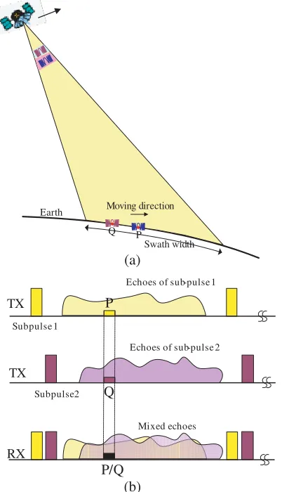
In conventional spaceborne SAR systems, only a pulse is transmitted in a single PRI. However, multiple innovative SAR imaging modes with several transmitted sub-pulses in a single PRI as shown in Fig. 1(a) are proposed to improve the HRWS capacity in recent years. These sub-pulses are with the same carrier frequency and phase coding but different transmitted time delays. Echoes corresponding to different sub-pulses are mixed in the receiving window as shown in Fig. 1(b). Fortunately, the mixed echoes corresponding to sub-pulse 1 and sub-pulse 2 arrive at the receiving antenna with different directions such as point targets P and Q in Fig. 1. As a result, echoes corresponding to different sub-pulses can be separated by the sharp receiving beam according to the relationship between the time delay and the side looking SAR imaging geometry.
Earth
Swath width P
Q
Moving direction
P
Echoes of sub-pulse 1 TX
Subpulse 1
Echoes of sub-pulse 2
TX
Subpulse 2 Q
Mixed echoes
RX
P/Q (a)
(b)
Figure 1. Spaceborne SAR imaging scheme with two sub-pulses transmitted in a single PRI. (a) The spaceborne imaging geometry. (b) The receiving window.
DB
F P
ro
ce
ss
or
N
1
Swath width
Nadir Ground
2 3
4
Pulse moving direction α
θ (τ)Sharp beam scan on receive
H
Sharp beam scan on receive
H
Figure 2 shows the imaging geometry of DBF on receive in elevation, where the large receiving antenna is divided into N sub-apertures, and each sub-aperture receives and records radar echoes individually. The normal direction of the receiving array antenna in elevation is denoted asα, and the radar echo arriving direction θ(τ) can be easily obtained according to the spaceborne SAR imaging geometry as follows:
θ(τ) = arccos
(Re+H)2+ (cτ/2)2−R2e
2(Re+H)·cτ
(1)
whereτ is the fast time, Re the Earth radius, H the satellite height, andc the light speed.
The demodulated baseband radar echo of then-th sub-aperture can be expressed as:
sn(τ) = rect
τ −τn
τp
·exp
j2πfc(τ −τn) +jπKr(τ−τn)2
(2)
with
τn=τd−
(n−1)·d·sin(θ0−α)
c =τd−Δτn (3)
where τp indicates the pulse duration, τd the time delay between the radar pulse transmit and its
corresponding echo receiving at the first sub-aperture as shown in Fig. 2, fc the carrier frequency, Kr
the transmitted pulse chirp rate, and θ0 the actual direction of arrival (DOA) of the received echoes.
According to the working principle of an array antenna, the multiplied beam steering vector w(τ) to form a sharp beam to receive echoes with the direction ofθ(τ) is as follows:
w(τ) = [w1, w2, . . . , wN] (4)
with
wn(τ) = exp
−j2π(n−1)·d
λ ·sin [θ(τ)−α]
(5)
Using the principle of stationary phase (POSP), the spectrum of the received signal in then-th channel after multiplying the steering vector w(τ) can be easily obtained and expressed as follows [14]:
Sn(f) = C·exp{−j2π(f+fc)τd} ·rect
f+ (n−1)·f0
Krτp
·exp
−j π
Krf
2
·exp
j2πf Δτn−
(n−1)
Kr ·f0
(6)
with
f0 = d
λ·cos [θ(τc)−α]·
∂θ(τc)
∂τ (7)
According to the spectrum in Eq. (6), the linear phase term should be compensated as follows:
Hf,n(f) = exp
−j2πf Δτn−
(n−1)f0
Kr
(8)
This step can also be implemented in the time domain via time delayDn as follows:
Dn= Δτn−
(n−1)f0
Kr
(9)
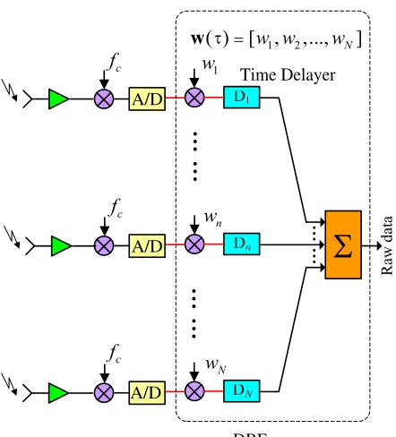
Therefore, a sharp high gain scanning beam to receive echoes is implemented via a multiplied vector and a set of time delayers. The block diagram of the real time conventional DBF processor in elevation onboard is shown in Fig. 3.
1
w
n
w
N
w
c
f
c
f
c
f
Ă
Ă
ĂĂ
ĂĂ
Ra
w d
ata
1 2
( ) [ ,w w ,...,wN]
w τ =
Time Delayer
DBF A/D
A/D
A/D
Σ
Figure 3. The block diagram of the real time conventional DBF processor in elevation onboard.
,1 f
H
,2 f
H
, f N
H
(a)
,1
n
h hn,2 hn,3 hn P,
( )
n s
( )
n n
s D
(b)
τ
τ + Σ
Figure 4. Implementation of the time delay in Fig. 3. (a) Implemented by the phase compensation in the frequency domain. (b) Implemented by the finite impulse response (FIR) filter.
(a) (b) (c)
-60 -40 -20 0 20 40 60
-10 -5 0 5 10
Re la tive time τ(μs)
A
m
p
lit
u
d
e
-60 -40 -20 0 20 40 60
-15 -10 -5 0 5 10 15
A
m
p
lit
u
d
e
-60 -40 -20 0 20 40 60
-15 -10 -5 0 5 10 15
A
m
p
lit
u
d
e
Re la tive time τ(μs) Re la tive time τ(μs)
Figure 5. Simulation results of DBF on receive in elevation. (a) Without any time delays. (b) The time delay implemented in the Doppler domain. (c) The time delay implemented by the sinc interpolator.
adaptive quantization (BAQ) data compression onboard. As we know, the time delay in digital signal processing can be implemented via N-order finite impulse response (FIR) filter as shown in Fig. 4(b), wherehn,p (p= 1,2,3, . . . , P) indicates the interpolation kernel function of the N-order FIR filter.
3. IMPROVED DBF PROCESSOR FOR ECHO SEPARATION
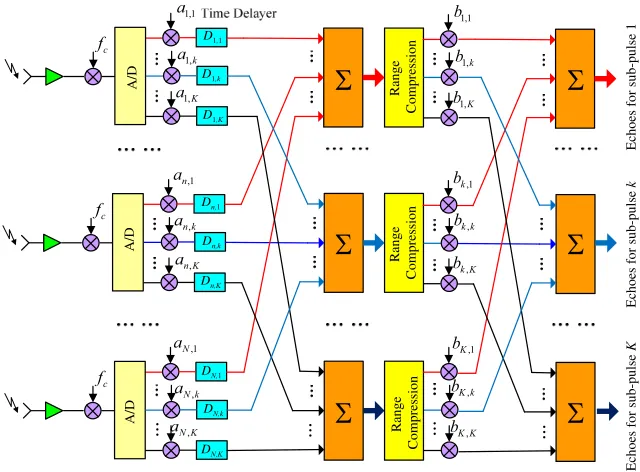
A block diagram of the proposed improved DBF processor for echoes separation is shown in Fig. 6, and the proposed processor includes three steps: multiple sharp scanning beams generation, range compression and interference echoes suppression by null steering. In Fig. 6, the number of sub-apertures in elevation and the number of sub-pulses transmitted in a single PRI are assumed as N and K, respectively, andN is larger thanK.
1,k
a
c
f
1,K
a
,
n k
a
c
f
,
n K
a 1,1 a
,1
n
a
,
N k
a
c
f
,
N K
a ,1
N
a
1,1 b
1,k
b
1,K
b
,1
k
b
,
k k
b
,
k K
b
,1
K
b
,
K k
b
,
K K
b
Echoes for sub-pulse
K
Echoes for sub-pulse
k
Echoes for sub-pulse 1
...
...
Range Compression
A/D
N,K
D
N,k
D
N,1
D
A/D
Range Compression
n,1
D
n,k
D
n,K
D
...
...
A/D
Range Compression 1,1
D
1,k
D
1,K
D
Σ
Σ
Σ
Σ
Σ
Σ
Figure 6. Block diagram of the proposed improved DBF processor for echoes separation.
The first step of the proposed DBF processor for multiple sharp scanning beams generation is controlled by the steering matrix A(τ) and a series of time delayers as show in Fig. 6. The steering matrixA(τ) can be expressed as follows:
A(τ) =
⎡ ⎢ ⎢ ⎣
a1(τ) a2(τ)
.. .
aK(τ)
⎤ ⎥ ⎥
⎦=
⎡ ⎢ ⎢ ⎣
a1,2 a1,2 . . . a1,N
a2,2 a2,2 . . . a2,N
..
. ... . .. ...
aK,1 aK,2 . . . aK,N
⎤ ⎥ ⎥
⎦ (10)
with
ak(τ) =
1,exp −j2π
λ d·sinθk(τ)
, . . . ,exp −j2π
λ (N −1)·d·sinθk(τ)
T
(11)
where symbol (·)T denotes the transpose operator, andθk(τ) indicates the sharp receiving beam pointing
direction for the k-th sub-pulse. The time delayerDn,k is described as follows:
Dn,k = Δτn,k−
(n−1)f0
Kr
= (n−1)·d·sin(θ0,k−α)
c −
(n−1)f0
Kr
(12)
whereθ0,k indicates the DOA of the received echoes for the k-th sub-pulse.
receiving beam is expressed as
sk(τ) =aTk(τ) [u1(τ),u2(τ), . . . ,uK(τ)]
⎡ ⎢ ⎣
σ1(τ)
σ2(τ)
. . .
σK(τ)
⎤ ⎥
⎦ (13)
with
uk(τ) =
1,exp j2π
λd·sinθk(τ +D2,k)
, . . . ,exp j2π
λ (N −1)·d·sinθk(τ+DN,k)
T
(14)
where σk(τ) indicates the range compressed radar echoes for the k-th sub-pulse. As a result, echoes
received by all sharp receiving beam can be written as
sk(τ) =
⎡ ⎢ ⎣
w1(τ) w2(τ)
. . .
wk(τ)
⎤ ⎥
⎦[u1(τ),u2(τ), . . . ,uK(τ)]
⎡ ⎢ ⎣
σ1(τ)
σ2(τ)
. . .
σK(τ)
⎤ ⎥
⎦=C(τ)
⎡ ⎢ ⎣
σ1(τ)
σ2(τ)
. . .
σK(τ)
⎤ ⎥
⎦ (15)
with
wk(τ) =
1,exp −j2π
λ d·sinθk(τ+D2,k)
, . . . ,exp −j2π
λ(N−1)·d·sinθk(τ +DN,k)
T
(16)
According to Eq. (15), the matrixB(τ) in Fig. 6 for null steering is easily obtained as follows:
B(τ) =
⎡
⎣ b1...,1 . . .. .. b1...,K
bK,1 . . . bK,K
⎤
⎦=C−1(τ) =
⎡
⎣ c1...,1 . . .. . . c1...,K
cK,1 . . . cK,K
⎤ ⎦
−1
(17)
with
cp,q(τ) =
N
n
exp
j2π
λd·(n−1)·[sin (θq(τn+Dn,q))−sin (θp(τn+Dn,p))]
,withp, q= 1,2, . . . , K
(18) Compared with the conventional DBF on receive method, the proposed DBF processor introduces null steering operation to improve performances of echoes separation corresponding to different sub-pulses. Furthermore, range compression for each receiving beam is carried out before the final null steering operation. The first step for multiple sharp scanning beams generation is implemented onboard, while the following steps for range compression and null steering can be finished on the ground. As the last two steps of the proposed DBF processor are operated on the ground, it will not increase any computation burden onboard compared with the conventional DBF on receive method. Furthermore, the data rate of the proposed DBF processor is the same as that of the conventional DBF processor.
4. SIMULATION EXPERIMENT
To validate the proposed DBF processor for echo separation, simulation experiments on point targets are carried out. Simulation parameters are listed in Table 1.
Assuming that there a point target in the imaged swath center, Fig. 7 shows simulation results of the conventional DBF processor, the DBF processor in [14] and the proposed DBF in this paper. Compared with results of the conventional DBF processor and the DBF processor in [14], undesired echoes are better suppressed in the proposed approach, which means that the proposed DBF processor with null steering shows better performance for echoes separation.
Table 1. Simulation parameters for echoes separation.
Simulation parameters value
Sensor height 675 km
Side looking angle 25o
Pulse duration 40µs
Pulse bandwidth 150 MHz
Sampling frequency 180 MHz The height of the receiving antenna 2.56 m
The height of the sub-aperture 0.32 m Number of sub-apertures 8 Number of sub-pulses in a PRI 2 The time delay between two sub-pulses 45µs
-150 -100 -50 0 50 100 150
-1 0 1
t(μs)
A m p litu d e
-15 -10 -5 0 5 10 15
-100 -50 0 Locat ion(km) A m pl it ud e( dB )
-50 0 50 100
-10 0 10
t(μs)
A m p litu d e
-50 0 50 100
-10 0 10
t(μs)
A m p litu d e
-100 -50 0 50 100
-10 0 10
t(μs)
A m p litu d e
-100 -50 0 50 100
-10 0 10
t(μs)
A
m
pl
it
ude
-15 -10 -5 0 5 10 15
-100 -50 0 Loca tion(km) A m pl it ude (d B )
-15 -10 -5 0 5 10 15
-100 -50 0 Loca tion(km) A m pl it ud e( dB )
-15 -10 -5 0 5 10 15
-100 -50 0 Locat ion(km) A m pl it ude (d B )
-15 -10 -5 0 5 10 15
-100 -50 0 Locat ion(km) A m pl it ud e( dB )
-15 -10 -5 0 5 10 15
-100 -50 0 Locat ion(km) A m pl it ude (d B )
-15 -10 -5 0 5 10 15
-100 -50 0 Locat ion(km) A m pl it ud e( dB )
(a) (b) (c)
(d) (e) (f)
-150 -100 -50 0 50 100 150 -5
0 5
t(μs)
A m p litu d e
-15 -10 -5 0 5 10 15
-100 -50 0 Locat ion(km) A m pl it ud e( dB )
-100 -50 0 50 100
-40 -20 0 20 40
t(μs)
A m p litu d e
-100 -50 0 50 100
-40 -20 0 20 40
t(μs)
A m p litu d e
-100 -50 0 50 100
-40 -20 0 20 40
t(μs)
A m p litu d e
-100 -50 0 50 100
-40 -20 0 20 40
t(μs)
A
m
pl
it
ude
-15 -10 -5 0 5 10 15
-100 -50 0 Loca tion(km) A m pl it ude (d B )
-15 -10 -5 0 5 10 15
-100 -50 0 Loca tion(km) A m pl it ud e( dB )
-15 -10 -5 0 5 10 15
-100 -50 0 Locat ion(km) A m pl it ude (d B )
-15 -10 -5 0 5 10 15
-100 -50 0 Locat ion(km) A m pl it ud e( dB )
-15 -10 -5 0 5 10 15
-100 -50 0 Locat ion(km) A m pl it ude (d B )
-15 -10 -5 0 5 10 15
-100 -50 0 Locat ion(km) A m pl it ud e( dB )
(a) (b) (c)
(d) (e) (f)
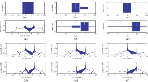
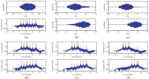
Figure 8. Simulation results of multiple point targets. (a) The real part of received echo in an individual elevation channel (top), the compressed data (bottom). (b) Echo separation results of the conventional DBF processor for the posterior beam (top) and the anterior beam (bottom). (c) Echo separation results of the null steering DBF processor in [14] for the posterior beam (top) and the anterior beam (bottom). (d) Compressed echo separation results of the conventional DBF processor for the posterior beam (top) and the anterior beam (bottom). (e) Compressed echo separation results of the null steering DBF processor in [14] for the posterior beam (top) and the anterior beam (bottom). (e) Compressed echo separation results of the proposed DBF processor for the posterior beam (top) and the anterior beam (bottom).
Table 2. Echoes separation result comparison of different DBF processors.
XXXXX
XXXXX
Approach
IL IL for receiving beam 1 (dB) IL for receiving beam 2 (dB)
P1 P2 P3 P4 P1 P2 P3 P4
Conventional
DBF processor 12.89 13.01 13.18 13.29 12.90 12.82 12.80 12.80 DBF processor
in [14] 39.82 40.19 40.38 40.51 39.98 39.87 39.89 39.89 Proposed
processor 62.35 55.72 51.02 49.93 56.57 67.90 68.48 68.04
5. CONCLUSION
performance. As the last steps of the proposed DBF processor can be implemented on the ground, the proposed processor does not increase any computation burden and data rate onboard
ACKNOWLEDGMENT
This work is supported by the NSF of China (No. 61271177).
REFERENCES
1. Gebert, N., “Multi-channel azimuth processing for high-resolution wide-swath SAR imaging,” Ph.D. dissertation, Univ. Karlsruhe, Karlsruhe, Germany, 2009.
2. Currie, A. and M. A. Brown, “Wide-swath SAR,” Proc. Inst. Electr. Eng. F — Radar Signal Process., Vol. 139, No. 2, 122–135, Apr. 1992.
3. Callaghan, G. D. and I. D. Longstaff, “Wide-swath space-borne SAR using a quad-element array,”
Proc. Inst. Electr. Eng. — Radar, Sonar Navig., Vol. 146, No. 3, 159–165, Jun. 1999.
4. Suess, M., B. Grafmueller, and R. Zahn, “A novel high resolution, wide swath SAR system,”Proc. IEEE Int. Geosci. Remote Sens. Symp., 1013–1015, Sydney, Australia, 2001.
5. Suess, M. and W. Wiesbeck, “Side-looking synthetic aperture radar system,” Euro Patent EP 1 241 487 A1, 2001.
6. Krieger, G., N. Gebert, M. Younis, and A. Moreira, “Advanced synthetic aperture radar based on digital beamforming and waveform diversity,” Proc. IEEE Radar Conf., 1–6, 2008.
7. Krieger, G., N. Gebert, and A. Moreira, “Multidimensional waveform encoding: A new digital beamforming technique for synthetic aperture radar remote sensing,”IEEE Trans. Geosci. Remote Sens., Vol. 46, No. 1, 31–46, Jan. 2008.
8. Wang, W.-Q., “Space-time coding MIMO-OFDM SAR for high-resolution imaging,” IEEE Trans. Geosci. Remote Sens., Vol. 49, No. 8, 3094–3104, Aug. 2011.
9. Wang, W.-Q., “Virtual antenna array analysis for MIMO synthetic aperture radars,” Int. J. Antennas Propag., Vol. 2012, 276, 587, 2012.
10. Wang, W.-Q., “Mitigating range ambiguities in high-PRF SAR with OFDM waveform diversity,”
IEEE Geosci. Remote Sens. Lett., Vol. 10, No. 1, 101–105, Jan. 2013.
11. Krieger, G., “MIMO-SAR: Opportunities and pitfalls,”IEEE Trans. Geosci. Remote Sens., Vol. 52, No. 5, 2628–2645, May 2014.
12. Kim, J., M. Younis, A. Moreira, and W. Wiesbeck, “A novel OFDM chirp waveform scheme for use of multiple transmitters in SAR,” IEEE Geosci. Remote Sens. Lett., Vol. 10, No. 3, 568–572, May 2013.
13. Xu, W., Y. Deng, and R. Wang, “Multichannel synthetic aperture radar systems with a planar antenna for future spaceborne microwave remote sensing,”IEEE Aerospace and Electronic Systems Magazine, Vol. 46, No. 12, 26–30, Dec. 2012.