241
Design & Implementation of Advanced Encryption &
Decryption Standard Algorithm for Security Using
Verilog
B. Anil Kumar1,V.Satyaarjun 2,K.Rujwala 3, K.Vinay pruthvi4
Dept. of ECE 1,Dept. of ECE2, Dept. of ECE3, Dept. of ECE4,MRIET1, MRIET2, MRIET3, MRIET4 ( Email: [email protected]1 ,[email protected]2 ,[email protected]3,
Abstract- Cryptography is the science of secure data transmission through an insecure channel. Advanced Encryption and decryption Standard is the most widely and secure symmetric key cryptographic algorithm today. AES algorithm is one on the most common and widely symmetric block cipher algorithm used in worldwide. This algorithm has an own particular structure to encrypt and decrypt sensitive data and is applied in hardware and software all over the world. It is extremely difficult to hackers to get the real data when encrypting by AES algorithm. Till date is not any evidence to crake this algorithm. AES has the ability to deal with three different key sizes such as AES 128, 192 and 256 bit and each of this ciphers has 128 bit block size. This paper will provide an overview of AES algorithm and explain several crucial features of this algorithm in details and demonstration some previous researches that have done on it with comparing to other algorithms such as DES, 3DES, Blowfish etc. The algorithm described by AES is a symmetric-key algorithm, meaning the same key is used for both encrypting and decrypting the data.
Keywords-cryptography,Encryption,Decryption,Permutation,Xilinx.Verilog,
1. INTRODUCTION
The requirements of information security with in an organization have undergone two major changes in the last several decades. Before the wide spread use of data processing equipment, the security of information felt to be valuable to an organization was provided primarily by physical and administrative means. An example of the former is the use of rugged filing cabinets with a combination lock for storing sensitive documents. With the introduction of the computer, the need for automated tools for protecting files and other information stored on the computer became evident. This is especially the case for shared system, such as a time-sharing system, and the need is even more acute for systems that can be accessed over a public telephone network, data network, or the Internet. The generic name for the collection of tools designed to protect data and to thwart hackers is computer security.
The second major change that affected security is the introduction of distributed systems and the use of networks and communications facilities for carrying data between terminal user and computer and between computer and computer. Network security
measures are needed to protect data during their transmission. In fact, term network
security is some what misleading, because virtually all business, government, and academic organizations interconnect their data processing equipment with a collection of interconnected networks. Such a collection is often referred to as an internet, and the term internet security is used.
2. LITRETURE SURVEY
The Advanced Encryption And Decryption
Standard also known by its specification for the encryption and decryption of electronic data established by the U.S. National institutes of standards and technology (NIST) in 2001.
The Advanced Encryption Standard (AES) algorithm is one of the block cipher encryption algorithm. The main aims of this algorithm was to replace DES algorithm after appearing some vulnerable aspects of it. NIST invited experts who work on encryption and data security all over the world to introduce an innovative block cipher algorithm to encrypt and decrypt data with powerful and complex structure.
242 cryptographers Joan Daeman and Vincent Rijndael.
The original name of AES algorithm is the Rijndael algorithm. However, this name has not become a popular name for this algorithm instead it is recognized as Advanced Encryption Standard (AES) algorithm around the world.
3. BLOCK DIAGRAM
Advanced Encryption Standard algorithm mainly consists of two blocks of description. The former segment refers to Encryption Block and the later one to Decryption Block.
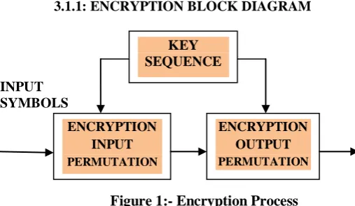
3.1.1: ENCRYPTION BLOCK DIAGRAM
INPUT SYMBOLS
Figure 1:- Encryption Process
Advanced Encryption standard(AES) explanation:
Block diagram of the AES system consists of a first permutation step applied to the input sequence and a second permutation step applied to the bits produced by the AES.A key sequence provides key information to both permutation steps.
[image:2.595.36.290.259.406.2]3.1.2: DECRYPTION BLOCK DIAGRAM:
Figure 2:- Decryption Process
Advanced Decryption standard(AES) explanation:
The output from the encryption block is taken as the input to the decryption block. The second stage of permutation is carried out through the bits produced by Advanced Decryption Standard . The input is recovered and shown at the explanation is done in above figures 1 and figure 2
3.1.PROCESS DESCRIPTION
INPUT SYMBOLS (288 BITS)
SYMBOL
NO 0
YES 1
KEYS
KEYS
OUTPUT
The description chart gives the overall view of the advanced technique equipped in the encryption and decryption techniques . The method what we use here is serial in parallel out format. In this we are using clock division checkbox of 36 Bytes which allows our input data to carry forward for the secure encryption process. The next block refers to the encryption ,Which allows the user to protect data from the third party(CYBER ATTACKS).In this process data encrypted through several row and column interchanging techniques. The main algorithm we use in encrypting and decrypting the data is PERMUTATION SYMMETRIC KEY ALGORITHM, Which means the same number of keys what we used in the input side i.e., in the encryption block are used at the output or at the end of data recovery.
DECRYPTION OUTPUT PERMUTATION
DECRYPTION OUTPUT PERMUTATION KEY
SEQUENCE
ENCRYPTION INPUT
PERMUTATION
ENCRYPTION OUTPUT
PERMUTATION KEY
SEQUENCE
ENCRYPTION
DECRYPTION
SIPO
243
3.1.4:DATA FLOW DIAGRAM
(i)FOR ENCRYPTION BLOCK
KEY(35:0)
INPUT SEQUENCE
CLK-DIV-(0) CODE
WORD
288 BITS ENCRYPTED WORD
[image:3.595.47.262.156.354.2]
KEY(71:36)
Figure 3:- Encryption Flow graph
The data flow diagram illustrates the entire encryption technique in the block .Formerly the code word is given to input block by using SIPO format. Then the codeword is encrypted by using symmetric permutation algorithm. The obtained codeword is known as encrypted codeword i.e., the output of encryption block which is taken as input for the decryption.
(ii):FOR DECRYPTION BLOCK
KEY(71:36))
CLK-DIV-(0)
CODE WORD
288 BITS RECOVERED
OUTPUT
KEY(35:0)
Figure 4:- Decryption Flow graph
The decryption block decodes the encrypted output by using the same permutation symmetric algorithm and recovers the original word.
4 .DESCRIPTION
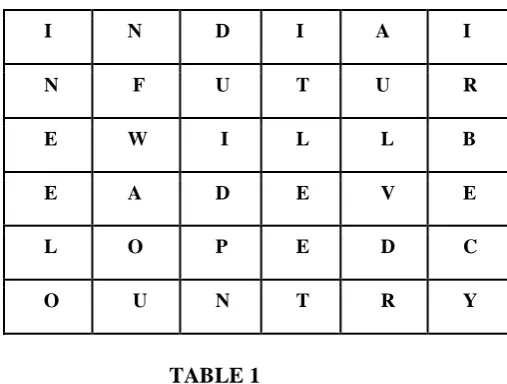
In this paper, We are implementing the AES by using symmetric algorithm in both Encryption and Decryption .Here we are going to implement the Key length of 192. Let us consider keyword of 36Bytes length and 288 Key permutations.
KEYWORD:
“ INDIA IN FUTURE WILL BE A DEVELOPED COUNTRY “
Here we convert the keyword in the array form for the permutation process.
ARRAY FORM:
I N D I A I
N F U T U R
E W I L L B
E A D E V E
L O P E D C
O U N T R Y
TABLE 1
The keyword undergoes sequence of permutations in both encryption and decryption. The below describes the process of both encryption block and decryption block.
PERMUTATIONS IN ENCRYPTION BLOCK:
Here the permutation undergoes row and column shifting by using the array format. Input permutation is used for encrypt the data by using the key, and Begins by mapping a sequence of length into a block having four columns and three rows. After the mapping, two key-driven cyclical shift steps are applied, one operating on the columns and the other operating on the rows. we are taking 24 bit key for encryption, in that 14 bits are used for input
SIPO
OUTPUT ENCRYPTION
INPUT
ENCRYPTION
SIPO
OUTPUT DECRYPTION
INPUT
[image:3.595.309.563.347.539.2]244 permutation. It takes 36 symbols(288 bits) when
clk_div_36 is high. Columns and rows are shifted depending on the keys
TABLE 2
ROW SHIFTING:
In the encryption process the first block refers to the encryption input. The given keyword input is row shifted i.e., towards left direction. Each row is shifted and the output is given to the encryption output block.
N D I A I I
F U T U R N
W I L L B E
A D E V E E
O P E D C L
U N T R Y O
ROW SHIFT
TABLE 3
COLUMN SHIFT:
The output from the row shift in the first block is now carried out through column shifting i.e., in upward direction.
F
U
T
U
R
N
W
I
L
L
B
E
A
D
E
V
E
E
O
P
E
D
C
L
U N
T
R
Y
O
N
D
I
A
I
I
TABLE 4
ENCRYPTION OUTPUT BLOCK:
The same process of shifting rows and columns has been carried out here ,the output obtained is known as encrypted code. The keys are shifted in a left ward direction and the output obtained performs column shifting .In the column shifting the keys performs the upward shift and the output is secured encrypted code.
ROW SHIFTING OUTPUT BLOCK & COLUMN SHIFTING OUTPUT BLOCK:
LEFT SHIFT
TABLE 5
DECRYPTION BLOCK EXPLANATION:
The output permutation operates on bits produced by arithmetic coder. output permutation encrypts the codeword data by using key value. we are taking 24 bit key for encryption, in that 14 bits are used for input permutation and remaining 10 bits are used for the output permutation. The column shifts are specified by a key, each column undergoing a upward cyclical shift in accordance with the key value associated with that column, columns and rows are
U T U R N F
I L L B E W
D E V E E A
P E D C L O
N T R Y O U
D I A I I N
I
L
L
B
E
W
D
E
V
E
E
A
P
E
D
C
L
O
N
T
R
Y
O
U
D
I
A
I
I
N
245 shifted depending on the key. It takes 36 symbols(288
bits) from arithmetic coding and it encrypts 36 symbols(288 bits). Decryption input permutation is used for decrypt the data by using the same key which used in encryption. The column shifts are specified by a key, each column undergoing a down ward cyclical shift in accordance with the key value associated with that column. Columns and rows are shifted depended on the key. Finally whatever the data we are giving to the encoder same data we are recovering at the output of the decoder.
COLUMN SHIFT:
TABLE 6
ROW SHIFT:
TABLE 7
DECRYPTION OUTPUT PERMUTATION EXPLANATION:
Decoder output permutation operates on bits produced by encrypted codeword of encoder output
permutation. whatever the key we are using in encryption same key we are using in decryption process. The column shifts are specific by a key, each column undergoing a down ward cyclical shift in accordance with the key value associated with that column. Columns and rows are shifted depending on the key. In decoder cyclic shifts reverse that of encoder should be performed.
COLUMN SHIFT:
TABLE 8
ROW SHIFT:
TABLE 9
5. RESULT:
The input codeword is :
“INDIA IN FUTURE WILL BE A DEVELOPED COUNTRY”.
N D I A I I
F U T U R N
W I L L B E
A D E V E E
O P E D C L
U N T R Y O U T U R N F
I L L B E W
D E V E E A
P E D C L O
N T R Y O U
D I A I I N
F U T U R N
W I L L B E
A D E V E E
O P E D C L
U N T R Y O
N D I A I I
I N D I A I
N F U T U R
E W I L L B
E A D E V E
L O P E D C
246 ENCRYPTED CODEWORD:
“ILLBEWDEVEEAPEDCLONTRYOUDIAIINUP URNS”
RECOVERED OUTPUT:
“INDIA IN FUTURE WILL BE A DEVELOPED COUNTRY”
Encrypt_ac_nbit_ver: Used for input permutation 36-bytes(288-bits):
Encrypt_ac_output_nbit_ver:
For output permutation 36-bytes(288-bits)
Decrypt_dc_input_nbit_ver 36-bytes(288-bits)
Decrypt_ad_nbit_ver 36-bytes(288-bits)
REFERENCES:
[1] Yang Jun Ding Jun Li Na Guo Yixiong (2010), FPGA based design and implementation of reduced AES algorithm, IEEE 978-0-7695-3972-0/10.
[2] Ahmad, N. Hasan, R., Jubadi, W.M. (2010), Design of AES SBox using combinational logic optimization, Advanced Encryption Standard for Altera Devices, SBCCI pp.
[3] “Secure Arithmetic Coding” Hyungjin Kim, Student Member, IEEE, Jiangtao Wen, Senior Member, IEEE, and John D. Villasenor, Senior Member, IEEE
[4] “Announcing the ADVANCED ENCRYPTION
STANDARD (AES)”, Fed. Inf. Process. Standards Pub. 197, 26, NIST, Nov. 2001.
[5] A. Moffat, R. M. Neal, and I. H.Witten, “Arithmetic coding revisited,” ACM Trans. Inf. Sys., vol. 16, no. 3, pp. 256–294, Jul. 1998. [6] R. R. Osorio and J. D. Bruguera, “A new
247 Mr. B. ANIL KUMAR ,
M.Tech working as Assistant professor ,in the Department of Electronics and communication , Mallareddy Institute of Engineering and Technology, Hyderabad. He studied
B.Tech in Electronics and Communications Engineering from JNTU college of Engineering, JNTUH, Hyderabad, Telangana and M.Tech in VLSI SYSTEM DESIGN From Aurora college of engineering, JNTUH, Hyderabad, Telangana.
V.SATYA ARJUN is studying B.Tech in (Electronics & Communication Engineering) at Mallareddy Institute of Engineering & Technology (MRIET), Hyderabad. Telangana.
K.RUJWALA is studying B.Tech in (Electronics & Communication Engineering) at Mallareddy Institute of Engineering & Technology (MRIET), Hyderabad. Telangana.