Variational time integrators in computational solid
mechanics
Thesis by
Adri´an Lew
In Partial Fulfillment of the Requirements for the Degree of
Doctor of Philosophy
California Institute of Technology Pasadena, California
2003
c
2003
To Patry, Jorge and Diana, Melisa and Dami´an,
Acknowledgements
I have greatly enjoyed my years at Caltech, not only because of the sunny beaches and close ski resorts of Southern California, but fundamentally because of the group of people with whom I shared these years. Having Michael Ortiz as thesis advisor has been a very enjoyable and fruitful experience. He has encouraged me to work on topics I had never before imagined I would, has taught me to be fearless of innovation and avid of self-renovation, and has been a constant driving force to embrace the scientific endeavor with passion and enthusiasm. I am deeply thankful for his guidance and support. I have also been very fortunate to meet Jerry Marsden at an early stage of my thesis work. He has certainly been and is a model to follow and look up to, but most importantly, it has always been a fascinating experience to talk and listen to him and to participate of the various activities his diverse range of interest generate. His characteristic research and writing style has definitively shaped my career. Professor Ravichandran has been the experienced mentor and friend I needed when planning my future steps. His dedication to mentoring students is truly an example I expect to follow. I would like to thank him for his guidance and support, and I am looking forward to continue listening more of his anecdotes in the future.
I would like to thank Kaushik Bhattacharya and Rob Phillips for the many interesting discussions we had during these years. Having Deborah Sulsky, Matt West, Raul Radovitzky, Patrizio Neff, Kyle Caspersen, Mark Scheel, Lee Lindblom, Mat´ıas Zielonka and Johannes Zimmer as collaborators has made research only more fun and interesting, and the long hours spent on it more enjoyable. I expect to continue our collaboration and friendship in the future. Deborah and Raul have also acted as mentors at different stages, and I would like to thank them for that. I will miss the afternoon strolls to the coffee house with my officemates in the room at the basement: Bill, John, Matt, Matias and Olga, and formerly Marisol, Enzo, Olivier, Puru and Rena. Marta and Lydia truly deserve separate credits, they have always showed patience and responsiveness whenever I rushed for their help. During these years I have enjoyed innumerable visits to the Athenaeum, outdoor adventures and sports with Julian, Florian, Alex and Pedro. They have generously offered me their friendship since the first day I arrived to the US, and made me feel at home away from home.
has provided me with the enthusiasm to face new projects and constantly seek novel challenges. I just want to thank them for that.
Abstract
This thesis develops the theory and implementation of variational integrators for computational solid mechanics problems, and to some extent, for fluid mechanics problems as well. Variational integrators for finite dimensional mechanical systems are succinctly reviewed, and used as the foun-dations for the extension to continuum systems. The latter is accomplished by way of a space–time formulation for Lagrangian continuum mechanics that unifies the derivation of the balance of lin-ear momentum, energy and configurational forces, all of them as Euler-Lagrange equations of an extended Hamilton’s principle. In this formulation, energy conservation and the path independence of the J- andL-integrals are conserved quantities emanating from Noether’s theorem. Variational integrators for continuum mechanics are constructed by mimicking this variational structure, and a discrete Noether’s theorem for rather general space–time discretizations is presented. Additionally, the algorithms are automatically (multi)symplectic, and the (multi)symplectic form is uniquely de-fined by the theory. For instance, in nonlinear elastodynamics the algorithms exactly preserve linear and angular momenta, whenever the continuous system does.
A class of variational algorithms is constructed, termed asynchronous variational integrators (AVI), which permit the selection of independent time steps in each element of a finite element mesh, and the local time steps need not bear an integral relation to each other. The conservation properties of both synchronous and asynchronous variational integrators are discussed in detail. In particular, AVI are found to nearly conserve energy both locally and globally, a distinguishing feature of variational integrators. The possibility of adapting the elemental time step to exactly satisfy the local energy balance equation, obtained from the extended variational principle, is analyzed. The AVI are also extended to include dissipative systems. The excellent accuracy, conservation and convergence characteristics of AVI are demonstrated via selected numerical examples, both for conservative and dissipative systems. In these tests AVI are found to result in substantial speedups, at equal accuracy, relative to explicit Newmark.
Contents
Acknowledgements iv
Abstract vi
List of Figures x
1 Introduction and overview 1
2 Variational time integrators for ODE 8
2.1 The basic idea . . . 8
2.1.1 Examples of discrete Lagrangians. . . 11
2.2 Conservation properties . . . 13
2.2.1 Noether’s theorem and momentum conservation . . . 13
2.2.2 Discrete time Noether’s theorem and discrete momenta . . . 14
2.3 Forcing and dissipation . . . 15
2.4 Constraints . . . 16
2.5 Symplecticity . . . 17
2.6 Convergence . . . 21
2.7 Implementation of variational integrators . . . 21
2.8 Is it possible to derive the algorithms from a minimum principle? . . . 23
2.9 When is an integrator variational? . . . 23
3 Asynchronous variational integrators 28 3.1 Formulation of the continuum problem . . . 29
3.1.1 Lagrangian description of motion . . . 29
3.1.2 Hyperelastic materials . . . 30
3.1.3 Viscous materials . . . 30
3.1.4 Hamilton’s principle . . . 31
3.1.5 Lagrange-D’alembert principle . . . 32
3.2.1 Spatial discretization . . . 33
3.2.2 Asynchronous time discretization . . . 34
3.2.3 Discrete Euler–Lagrange equations . . . 37
3.2.4 Discrete Lagrange-D’alembert principle for asynchronous discretizations . . . 39
3.3 Implementation of AVIs . . . 39
3.4 Momentum conservation properties . . . 41
3.5 Numerical examples . . . 43
3.5.1 Two–dimensional Neohookean block . . . 44
3.5.2 Three–dimensional L–shaped beam . . . 48
3.5.3 Dynamics of the rotor blades of an Apache AH-64 helicopter . . . 49
3.5.4 Shock-loaded thermoelastic materials and high-explosive detonation waves . . 53
3.5.4.1 Internal energy balance equation . . . 57
3.5.4.2 Thermoelastic materials . . . 57
3.5.4.3 Artificial viscosity . . . 58
3.5.4.4 Plate impact experiment on tantalum . . . 60
3.5.4.5 Plate impact experiment on a high-explosive material . . . 66
3.5.4.6 Contained detonation of a high-explosive material . . . 71
3.6 Complexity and convergence . . . 73
3.7 Extension of AVIs . . . 79
3.8 Periodic boundary conditions . . . 81
4 Time-adaption and discrete path integrals 83 4.1 Space–time Lagrangian mechanics . . . 83
4.1.1 Variational principles and equations of motion . . . 84
4.1.2 Noether’s theorem and momentum conservation . . . 86
4.1.3 Restated variational principles and configurational forces . . . 87
4.1.4 Time symmetry and energy conservation . . . 90
4.1.5 Reference symmetries and conserved path integrals . . . 91
4.1.6 Multisymplecticity . . . 92
4.2 Time adaption and discrete path independent integrals . . . 94
4.2.1 Discrete energy conservation for ODEs . . . 94
4.2.2 Discrete energy conservation for AVIs . . . 97
4.2.3 Implementation of time step adaption for AVIs . . . 101
4.2.4 Energy reservoirs and time step adaption . . . 103
4.2.4.1 Energy reservoirs and optimal energy balance . . . 104
4.2.6 Discrete horizontal and vertical variations: discussion . . . 108 4.3 Discrete multisymplecticity . . . 109 4.4 Discrete Noether’s theorem (Asynchronous case) . . . 109
List of Figures
2.1 For the continuous variational principle we compare curves in the configuration space Q, while for the discrete variational principle the comparison is between neighboring
points inQ. In both cases, the variationsδqare tangent toQ. . . . 10
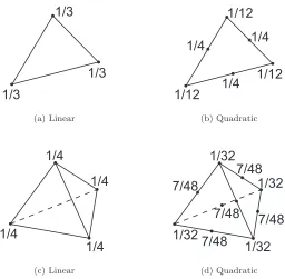
3.1 Mass lumping schemes for linear and quadratic triangles and tetrahedra. The number beside a node indicates the fraction of the total mass of the element that is assigned to it. . . 34 3.2 Space–time diagram of the motion of a two–element, one–dimensional mesh. The set
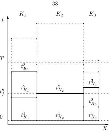
of coordinates and times for a single node is shown in the reference and deformed configuration. Note that the nodal coordinates and times are labeled according to the interaction of the node with all elements to which it belongs. The horizontal segments above each elementK define the set ΘK. . . 35 3.3 Configuration number 8 (in thick lines) for the space–time diagram shown,
correspond-ing to a one–dimensional three-element mesh. Θ ={t1
K1, t1K2, t1K3, t2K3, tK21, t2K2, tK33, t3K1, . . .},
NT = 3 and NΘ= 13. . . 38 3.4 Algorithm implementing the discrete Euler–Lagrange equations of the action sum given
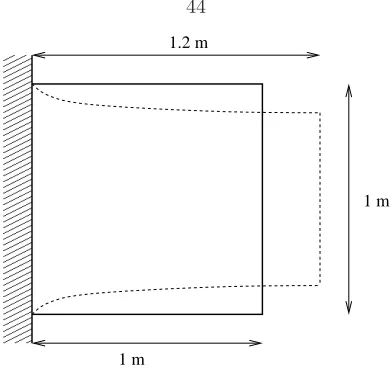
by equation (3.39). . . 40 3.5 Geometry of the two–dimensional Neohookean block example. . . 44 3.6 Neohookean block example. Snapshots of the deformed shape of the block at intervals
of 2×10⁻⁴s. Time increases from left to right and from top to bottom of the figure. 45 3.7 Neohookean block example. Comparison of the deformed configurations at t = 16
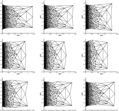
ms computed using Newmark’s second-order explicit algorithm (dashed lines) and the AVI (solid lines). The time corresponds to 2,208,000 Newmark steps, or 8 complete oscillation cycles. . . 46 3.8 Neohookean block example. Contour plot of the log10 of the number of times each
3.12 L-shaped beam example. Total energy as a function of time as computed by the AVI. 49 3.13 Apache AH-64 helicopter . . . 50 3.14 Cross section of the blade. For the example, the complex composite structure has been
replaced by a homogeneous solid one. . . 51 3.15 Mesh of the blade. It consists of 2089 ten-noded tetrahedral elements and 4420 nodes. 52 3.16 Evolution of the blade for the first and most rigid case. The motion of the blade is
essentially that of a rigid body. The center of mass does not move, a consequence of the discrete linear momentum conservation, and the period of the blade is very close to the one of a completely rigid blade, since the spanwise elongation is negligible. The final snapshots correspond to approximately 266 million updates of the smallest element in the mesh. . . 54 3.17 Evolution of the blade for the second case. During the initial phases of the motion,
some fairly large deflections, including torsion along the spanwise direction, occur. However, after a relatively long time the blade rotates with an almost fixed shape. The period of rotation has changed slightly with respect to a rigid blade, since there is a non-negligible spanwise elongation inducing a change in the corresponding moment of inertia. The final snapshots correspond to approximately 325 million updates of the smallest element in the mesh. . . 55 3.18 Evolution of the blade for the third and softest case. During the initial phases of the
motion, the blade behaves as a very flexible strip. Surprisingly, after a relatively long time the blade settles to rotate with small amplitude oscillation close to an almost fixed shape. The period of rotation with respect to a rigid blade has changed considerably, since the spanwise elongation is large. The final snapshots correspond to approximately 234 million updates of the smallest element in the mesh. . . 55 3.19 Contour plot of the log10 of the number of times each element was updated by the
AVI after 27.439 s of simulation of case 3, in which inertial forces prevail. The picture on the middle shows an enlargement of the central part of the blade, which is made out of a stiffer material than the rest. The abrupt change in the number of elemental updates between the two regions is noteworthy. Additionally, the picture on the top shows only those few elements updated more than 108times. These elements or slivers would drive the whole computation down for a constant time step algorithm, while AVI circumvents this difficulty gracefully. . . 56 3.20 Evolution of the total energy in the blade as a function of the number of revolutions
3.21 Schematic of plate impact problem . . . 61 3.22 Snapshots of the evolution of the shock wave advancing through the cylinder. In
addition to the mesh, each snapshot depicts contour plots for the axial velocity. . . 63 3.23 Profile and contours of the axial velocity and the Jacobian of the deformation mapping,
drawn at time t=12.1 µs on one of the planes that contains the cylinder axis. The shock is well captured by the artificial viscosity and spread along approximately 6 elements. The wall overheating effect is noticeable near the impact surface in the plot of the Jacobian, as is commonly observed in other artificial viscosity schemes. Even though the time step far from the shock approaches the one given by the local Courant condition, the solutions do not appear to possess any apparent instability. . . 64 3.24 Sequence of snapshots showing the evolution of the pressure (top) and the number
of time steps each element performs during a preset time interval (bottom). Both fields are drawn on a plane that contains the cylinder axis. Outside the shock region, the elemental time step is very close to that given by the Courant condition. The ratio maximum/minimum number of updates is always of the order 10, i.e., the ratio minimum/maximum elemental time step is of the order 10−1. . . 65 3.25 Snapshots of the evolution of the detonation front and deformation of the cylinder. In
addition to the mesh, each snapshot depicts contour plots for the axial velocity. . . 68 3.26 Profile and contours of the axial velocity and the Jacobian of the deformation mapping
on one of the planes that contains the cylinder axis, at time t=7.75µs. The irregular over- and under-shoot in the velocity is due to the fact that the mesh is too coarse to resolve the detonation profile. . . 68 3.27 Sequence of snapshots showing the evolution of the pressure (top) and the number of
time steps each element performs during a preset time interval (bottom). All pictures show the values of the corresponding fields on a plane that contains the cylinder axis. Notice the logarithmic scale on the vertical axis of the number of updates each elements performs. It is remarkable that the ratio maximum/minimum number of updates is always of the order 104, i.e., the ratio minimum/maximum elemental time step is of the order 10−4. . . . 69 3.28 Evolution of the pressure and the number of elemental updates during a given time
3.29 Evolution of a detonation wave within a solid canister. The detonation is initiated by impacting one of the planar surfaces of the set canister-explosive. The pictures show the evolution of the number of elemental updates during a preset time interval (lower half of each snapshot) and the pressure contours (upper half of each snapshot), both in the explosive and in the sorrounding solid. The plots of the number of elemental updates only show values on a plane of the cylinder that contains its axis, and can be roughly described as composed of three strips. The central strip, which lies in the explosive region, has fewer elemental updates than the two thin lateral strips, which lie in the solid canister region. The sequence continues in Figure 3.30. . . 74 3.30 Evolution of a detonation wave within a solid canister. The sequence of snapshots
begins in Figure 3.29. The detonation is initiated by impacting one of the planar surfaces of the set canister-explosive. The pictures show the evolution of the number of elemental updates during a preset time interval (lower half of each snapshot) and the pressure contours (upper half of each snapshot), both in the explosive and in the sorrounding solid. The plots of the number of elemental updates only show values on a plane of the cylinder that contains its axis, and can be roughly described as composed of three strips. The central strip, which lies in the explosive region, has fewer elemental updates than the two thin lateral strips, which lie in the solid canister region. . . 75 3.31 Four different views of the same pressure surface on one plane of the set
canister-explosive at time 9.9µs. . . . 76 3.32 Schematic diagram of the geometry of the slab and the coarsest mesh for the cost/accuracy
example . . . 77 3.33 L2errors for the displacement (on the left) and the deformation gradient (on the right)
as a function of the number of elemental updates for the slab problem. As is readily seen from the plots, AVIs are substantially cheaper than Newmark in computational cost for a desired error value. . . 79
4.1 Schematic representation of the relation betweenγ,φandϕ. The parametric configu-ration ¯X and the reference configurationX are isomorphic. . . 87 4.2 Graphical representation of vertical and horizontal variations. The thick line is a
4.3 A graphical representation of a deformation mappingϕfor elastodynamics. The hor-izontal axes represent space–time and together they form the reference configuration
X =R× B. The vertical axis represents Rn where the deformed configuration lives.
Taking a slice ofϕwith constantX gives the trajectory of the particle with material coordinatesX for all time. Alternatively, taking a slice ofϕwith constantt∈Rgives the configuration of the entire body at a single instant of time. Note that any motion of the continuum is represented as a surface in this diagram. . . 89 4.4 Graphical interpretation of the algorithm. There are two intersections of the constant
energy and momentum surfaces. The cross denotes a solution rendering a negative value of ˆhi+1/2, while the circle indicates the positive solution. . . . 95 4.5 Evolution of the residual of the energy balance equation (4.31) (or energy “imbalance”)
and the total energy of the same element for one element of the mesh chosen at random. Even though the residual of the energy equation is not exactly zero, the absolute size of the energy “imbalance” is negligible when compared with the total energy in the element. The local energy balance is “nearly” satisfied at all times, even though this equation is never enforced. This curves were obtained from the case 3 of the helicopter blade example in section§3.5. . . 101 4.6 Neohookean block example. Instantaneous and accumulated local energy residual as a
function of time for an element of the mesh. The accumulated energy residual remains below 0.3% of the value of the elemental energy at all times after an initial transient. Some high-frequency ringing is evident, as is typical of quadratic triangular elements. 102 4.7 L-shaped beam example. Instantaneous and accumulated local energy residual as a
function of time for an element of the mesh. The accumulated energy residual remains below 0.03% of the value of the elemental energy at all times. . . 102 4.8 Neohookean block example. Histogram of the distribution of maximum relative error
in satisfying the local energy equation on each element up to time t = 8.8 ms. The relative error is defined as the absolute value of the quotient between the residual of the the local energy equation and the instantaneous total energy in the element. More than 50% of the elements have a maximum relative error smaller than 0.1%, while 97.5 % of the elements have a maximum relative error smaller that 1%. . . 103 4.9 Total energy as a function of time for the Neohookean block example, when the
dy-namics of the local energy reservoirs are chosen to be determined by the optimization procedure. . . 105 4.10 Example of a subset of elementsτin a finite element mesh. The elements in the shaded
4.11 Example finite element mesh for a two–dimensional fracture mechanics simulation. If the configurational forces are in equilibrium, then expression (4.53) evaluated on∂τ is equal to the J-integral. The value of the J-integral is the same when computed on the boundary of any submeshτ that contains the node at the crack tip. . . 107 4.12 Graphical representation of horizontal and vertical variations for a finite element
List of Tables
3.1 Neohookean block example. Number of elemental updates after 10 ms of simulation. . 44 3.2 Period of rotation of the blade for long times. As the value of ˆω grows, the blade
deforms more increasing its span, and therefore its moment of inertia, to accommodate the centrifugal forces. Since the discrete angular momentum is conserved, the period of rotation should grow accordingly. . . 52 3.3 Maximum and minimum number of elemental updates for a single element at the final
time. The total column shows the sum of the number of elemental updates in the whole mesh at the final time. In contrast, traditional time stepping algorithms would have advanced with the same number of updates on each element, which is equal to the value in the Maximum column. The ratio between the total number of updates in the whole mesh in these two cases is shown in the Speed-up column, a direct measure of the cost saving features of AVI. . . 53 3.4 Comparison between theoretical and numerical values of pressure, specific volume, and
temperature after the shock. D is the shock velocity. . . 64 3.5 Comparison of the theoretical and numerical predictions for the state of the material
Chapter 1
Introduction and overview
The goal of this thesis is to present a new framework and a fresh perspective on the formulation of computational algorithms for solid and fluid mechanics. Despite the undeniable success of the finite element and related methods, the quest for building virtual laboratories where virtual experiments could be performed demands the careful crafting of newer and more powerful algorithms, but most importantly, it demands the creation of a new level of understanding of mechanics when the contin-uum is discretized. The theory of Discrete Mechanics has been and is being developed to fulfill this need. In particular, this thesis contains the formulation of the theory for solid mechanics and some fluid mechanics problems.
The cornerstone of the theory of Discrete Mechanics consists of discretizing Hamilton’s principle of stationary action in Lagrangian mechanics. While this idea is standard for elliptic problems, in the form of Galerkin and finite element methods (see, e.g., Johnson [1987]), it has only been applied relatively recently to derive variational time stepping algorithms for mechanical systems. We refer to Marsden and West [2001] for an extensive survey of the previous literature, as well as for a detailed overview of the framework for problems described by ordinary differential equations (ODE).
The remarkable conservation properties of the resulting algorithms represent perhaps the most profound consequence of the variational structure of the theory. This is precisely stated in the existence of a discrete version of Noether’s theorem (see, e.g., Marsden and Ratiu [1994]), namely, there is a conserved quantity associated with each symmetry of the discrete mechanical system. In other words, if one constructs the discrete variational principle to respect the symmetry (such as rotational invariance for angular momentum), then there will be a corresponding conserved quantity that is exactly respected by the discrete algorithm. Of course it is well known (and examples are given in Lew et al. [2003b]) that standard, unstructured, even more highly accurate algorithms do not have this property.
But there is more to the story. In addition to the superb conservation properties, every algorithm constructed from the theory is symplectic (see, e.g., Marsden and West [2001]), in the same way the flow of the continuous system is (see, e.g., Marsden and Ratiu [1994]). Symplectic algorithms have often been observed computationally to possess remarkable near energy preserving behavior, which makes them very attractive for long–time integration. Simplecticity is a statement about the way nearby trajectories of the mechanical system evolve. Liouville’s theorem, which states that any open set in phase space is evolved isochorically by the mechanical system, can be regarded as a direct consequence of the symplecticity of the flow of the continuous system. This by itself may seem somewhat mathematical and irrelevant at first sight, but it is the key to understanding the remarkable energy behavior of variational schemes. We shall explain the notion of symplecticity in concrete and easy to understand terms in the text, but it is a deep notion that underlies all of modern geometric mechanics. In particular, through a process calledbackward error analysis, it is the key to understanding this approximate energy conservation. The basic idea is to show that the algorithm is exactly energy conserving (up to exponentially small terms) for anearbyHamiltonian system. This is important work of many people; we refer to Hairer and Lubich [2000] for one of these and to Marsden and West [2001] for additional references.
appropriate to mention, however, that exactly preserving the energy by adjusting the time step is sometimes at conflict with other considerations, such as stability analysis or computational efficiency. Widely used algorithms can be recast into the discrete mechanics framework, such as some versions of Newmark, as done in Kane et al. [2000]. In molecular dynamics symplectic algorithms are known to perform very well. The ability of variational integrators to capture statistical quantities right has long been known, even in the face of chaotic dynamics where small perturbations can lead to large errors in specific trajectories. A neat example is presented in Lew et al. [2003b] in the computation of the average kinetic energy of a system of interacting particles. The theory sheds light on some of the reasons for the observed good behavior of these algorithms; but fundamentally, it facilitates and guides the construction of integration schemes in nonstandard situations.
The theory is not limited to conservative systems. The extension of the theory to dissipative or forced systems has been carried out in Kane et al. [2000] through the application of the Lagrange-D’alembert variational principle. This guarantees that the discretization of the conservative part of the forces retains good preservation properties, which proves to be fundamental to correctly capturing the dissipation rate in weakly dissipative systems (see Kane et al. [2000]). Additionally, if there are constraints present, then one can still use, very effectively, variational methods. The constraints are realized in terms of the Lagrangian augmented by suitable penalty functions. Variational methods have also been applied to collision algorithms, as in Kane et al. [1999b], Pandolfi et al. [2002], Fetecau et al. [2002] and references therein. The main achievement in these works is to show that properties of variational integrators remain valid right through the collision process.
Chapter 2 reviews the basic aspects of the theory of Discrete Mechanics, briefly described above. We made every effort to provide a description of the theory in simple and elementary terms, directed to those readers who are not very familiar with differential geometry terminology. This chapter, as well as Lew et al. [2003b], are intended to be an introduction to the subject. To fully understand the theory, it is best to work intrinsically on manifolds as opposed to relying on generalized coordinates. We refer the reader to Marsden and West [2001] for the intrinsic version. The chapter also includes a few new components, such as a discussion of when a given algorithm is variational, conditions for a variational algorithm to derive from a minimum principle, and the treatment of two-point constraints, so necessary for solid mechanics applications.
action sum is constructed by adding contributions from all discrete regions in space–time, normally called discrete Lagrangians, and the trajectories are obtained by applying Hamilton’s principle as in the finite–dimensional case. A discrete Noether’s theorem is also obtained in this context, having a powerful additional feature. Not only does it guarantee the conservation of global quantities, such as total angular momentum, but it also shows that the resulting algorithms possess detailed conservation properties at the local level as well. This is just a consequence of the local character of the Lagrangian, and therefore the discrete Lagrangians, for continuum mechanics. For more general Lagrangians this is of course not necessarily true.
In adopting the space–time perspective one is naturally led to consider algorithms based on multiresolution discretizations, both in space and time. We propose herein a class of powerful dis-cretizations based on a decomposition of space, with finite elements for instance, and the freedom to choose the size of the time interval over each spatial domain, i.e., the time step at each point in space–time. The resulting variational algorithms are termed asynchronous variational integrators (AVI). In particular, when applied to dynamical systems defined by the finite element method, AVIs permit the selection of different time steps for each element. The local time steps need not bear an integral relation to each other, and the integration of the elements may, therefore, be carried out asynchronously.
The asynchronous algorithms developed within this thesis share many features with multi-time step integration algorithms, sometimes termed subcycling methods. These algorithms have been developed in Neal and Belytschko [1989] and Belytschko and Mullen [1976], mainly to allow stiff elements, or regions of the model, to advance at smaller time steps than the more compliant ones. In its original version, the method grouped the nodes of the mesh and assigned to each group a different time step. Adjacent groups of nodes were constrained to have integer time step ratios (see Belytschko and Mullen [1976]), a condition that was relaxed in Neal and Belytschko [1989] and Belytschko [1981]. Recently an implicit multi-time step integration method was developed and analyzed in Smolinski and Wu [1998]. We also mention the related work done by Hughes and Liu [1978] and Hughes et al. [1979]. The freedom to choose the time step for each element, subject to stability considerations, as well as the way nodes are updated, are the distinguishing features of the asynchronous algorithms introduced here.
AVIs sidestep these difficulties by allowing each element or region of space to advance at their own intrinsic pace. There are, in addition, several other application areas that badly need AVI-like al-gorithms, most notably with the fast development of complex multiscale material models. In this context, the core of the computational cost for finite element simulations has shifted from assembling forces and computing displacements to the elemental computations, which usually involve the use of elaborate material constitutive models. In addition to the thermoelastic problem, other physical processes are often considered as well, such as plastic deformation, chemical reactions and phase transitions. Highly spatially localized timescales can be induced by any or all of these processes. For instance, the propagation of a detonation wave in a thermoelastic material induces the usually faster timescale of the chemical reaction in the region surrounding the detonation front. Not only do we need spatially resolved meshes to accurately capture the detonation front, but the use of AVIs becomes essential if any meaningful time is to be reached by the simulation. We note additionally that despite the growing computational power provided by highly parallel machines, solutions are still obtained by advancing forward in time, which makes AVIs even more fundamental for large-scale simulations in the near future.
There are also many connections between the multi-time step impulse method (also known as Verlet-I and r-RESPA), which is popular in molecular dynamics applications, and the AVI algorithm here (see Grubm¨uller et al. [1991] and Tuckerman et al. [1992]). Thus, when applied to a system of ODEs the AVI method may be regarded as a fully asynchronous generalization of the impulse method.
Chapter 3 fully develops the theory and implementation of AVIs for continuum mechanics prob-lems. It introduces a particular class of space–time discretization and defines the discrete La-grangians. It then analyzes the momentum conservation properties, and provides the expressions for the preserved discrete linear and angular momentum. Notice that once the action sum has been postulated, all of the relevant discrete mechanical quantities emanate uniquely from the theory, even in cases where otherwise only expert guessing or “luck” would be required. Several numerical examples for hyperelastic and thermoelastic materials are presented to illustrate the versatility and robustness of the new concepts. In particular, we use AVIs to simulate the propagation of a high-explosive detonation wave within a solid canister. To numerically capture the shock preceding the detonation wave we briefly present an artificial viscosity scheme developed in Lew et al. [2001], as well as the extension of AVIs to dissipative systems.
material and spatial variations and symmetries as special cases. Even though similar formulations have been known for some time, we felt it deserved to be included to make the parallel between the continuous and discrete theories of Mechanics complete and transparent. This formulation unites en-ergy, configurational forces and the Euler–Lagrange equations within a single picture, and naturally delivers the aforementioned conservation laws.
In particular, energy conservation can be regarded both as one of the Euler–Lagrange equations stemming from the space–time formulation, as well as the conservation law associated with invariance under time translations. Correspondingly, in the discrete picture we consider the AVI’s time steps as part of the dynamical variables, and obtain the associated discrete Euler–Lagrange equations. These equations can be recognized as local energy balance equations, and are expected to be satisfied by choosing the value of the time step at each point in space–time. In this case, a discrete version of Noether’s theorem guarantees theexact conservation of energy both locally and globally. Perhaps the greatest difference with the continuum case is that the DEL equations expressing the local linear momentum balance do not imply the DEL equation expressing the local energy balance. As we shall have the opportunity to see in Chapter 4, there are good reasons for this and it has very important consequences.
Unfortunately, the local energy balance equation generally involves the unknown time step in a highly nonlinear way. Very often it is not possible to find a suitable time step that satisfies this equation. Nevertheless, as the numerous examples in Chapter 4 show, even without deliberately adjusting the time step to achieve exact conservation these algorithms possess remarkable local and global energy conservation properties, which probably originate from their symplectic and variational nature.
One of the most pleasing aspects of the space–time picture of Lagrangian mechanics is that it contains elastostatics as a particular case, in which the action becomes the potential energy of the system and Hamilton’s principle translates into seeking the minimum energy configuration. Configurational forces (see, e.g., Gurtin [2000]), the driving forces behind phase transformations and crack propagation for instance, are obtained from the space–time formulation on an equal footing with energy, in as much as time and spatial coordinates are regarded on an equal footing. The static J and L path independent integrals, widely used in fracture mechanics and to compute forces over inclusions and defects, are the conserved quantities related to configurational forces. They stem from the invariance of the elastic energy of a homogeneous material under rigid translations and rotations in the reference configuration.
and it reduces to a set of equations where the parameters defining the spatial discretization, i.e., the positions of the nodes, have to be solved for. The resulting mesh adaption methodology is termedvariational arbitrary Lagrangian–Eulerian (VALE) method, and it was initially developed and proposed in Thoutireddy and Ortiz [2003]. In Chapter 4 the discrete path independent J and L integrals are defined and shown to be preserved over any closed surface in the mesh.
The analog to symplecticity in the continuum mechanics setting is termed multisymplecticity, and it is briefly discussed in Chapter 4. In some cases, multisymplecticity reduces to well known and easy to understand principles, including the Betti reciprocity principle and other well known reciprocity principles in mechanics.
Chapter 2
Variational time integrators for
ODE
In this chapter we review the fundamental facts about variational integrators and Discrete Mechanics. The chapter summarizes the main results of the theory in very simple and easy to understand terms, while we add a few more. The original contributions in this chapter include the formulation of two– point constraints and the discussions in sections 2.8 and 2.9. For a thorough and comprehensive description of the theory we refer the reader to Marsden and West [2001].
For the sake of readability, we confine ourselves in this thesis to work in coordinates. We do include, however, geometrical asides in order to hint at the more general manifold picture. These short but explanatory paragraphs have been included in Lew et al. [2003b], and they have been mainly written by Matt West while collaborating in the aforementioned manuscript.
2.1
The basic idea
A bumper sticker explaining how to construct variational integrators would read
“Approximate the action instead of directly approximating the equations of motion.”
This simple idea turns out to be very powerful, as we shall have the opportunity to explore in this thesis. In fact, it has underpinned the solutions to elastostatics problems with the finite element method for fifty years now. To explain the implications of the above bumper sticker, in the following we briefly review the Lagrangian formulation of the mechanics of a conservative system, and then we mimic this process at the discrete level to construct variational integrators.
Continuous time Lagrangian mechanics We consider a conservative mechanical system with a LagrangianL(q,q), where˙ q= (q1, q2, . . . , qn) is a point in the configuration spaceQ. In Lagrangian
curvesq(t) for which the action functional
S[q(t)] =
b
a
L(q,q)dt˙ (2.1)
is stationary when compared with other curves with the same endpoints at timesaandb. In other words,q(t) should satisfy
δS =
b
a
d dt
∂L ∂q˙ −
∂L ∂q
·δq dt+∂L ∂q˙ ·δq
b
a= 0, (2.2)
for all variationsδq such thatδq(a) =δq(b) = 0. The corresponding Euler–Lagrange equations are
d dt
∂L ∂q˙ −
∂L
∂q˙ = 0. (2.3)
For completeness, we recall the definition of a variation of a curveq(t) as given in Marsden and Ratiu [1994]. Consider a one–parameter family of curves qε(t) in Qsuch thatq0(t) =q(t). Associated to qε(t) we define avariationδq(t) as
δq(t) = ∂q
ε(t)
∂ε
ε=0.
Discrete time Lagrangian mechanics. A variational integrator for a conservative mechanical system is constructed by approximating the action integral (2.1) with anaction sum
Sd= N−1
k=0
Ld(qk, qk+1, tk, tk+1), (2.4)
whereLdis thediscrete Lagrangianand (qk, tk),k= 0, . . . , N, are the points and times defining the discrete trajectory. The discrete Lagrangian is constructed as a good approximation to the action functional for the exact trajectoryq(t), i.e.,
Ld(q(tk), q(tk+1), tk, tk+1)≈
tk+1
tk
L(q,q)˙ dt. (2.5)
Note that we have taken the discrete Lagrangian to be a function of two points inQand two times. We shall see examples of more general dependence later in the thesis, especially in the formulation of higher-order integrators1 and asynchronous methods.
The discrete trajectory follows after applying thediscrete variational principle, namely, we seek points {qk}k=0,...,N such that the discrete action sum is stationary under all admissible variations
that keep the end pointsq0, qN fixed. The variations of theSd follow from
δSd=D1Ld(q0, q1, t0, t1)·δq0+D2Ld(qN−1, qN, tN−1, tN)·δqN
+
N−1
k=1
[D1Ld(qk, qk+1, tk, tk+1) +D2Ld(qk−1, qk, tk−1, tk)]·δqk. (2.6)
We obtain in this way thediscrete Euler–Lagrangeequations
D1Ld(qk, qk+1, tk, tk+1) +D2Ld(qk−1, qk, tk−1, tk) = 0, (2.7)
where we henceforth denote withDiLd the slot derivative with respect to thei-th argument inLd.
Assuming that the sequence of time steps is seta priori, equation (2.7) implicitly defines a mapping (qk−1, qk)→(qk, qk+1), the algorithm to advance the solution in time given initial conditions (q0, q1).
The geometric picture. The connection between the continuous and discrete variational prin-ciples is graphically represented in Figure 2.1. This geometric interpretation becomes of utmost importance when analyzing symmetries and conservation laws of the continuous and discrete vari-ational principles, as we shall see later. A thorough description of the underlying geometry for variational integrators is provided in Marsden and West [2001].
Q
q(t)
δq(t)
(a) Continuous variational principle
Q
q
δqi
i
(b) Discrete variational principle
Figure 2.1: For the continuous variational principle we compare curves in the configuration space Q, while for the discrete variational principle the comparison is between neighboring points inQ. In both cases, the variationsδqare tangent toQ.
if
Ld(q0, q1, t0, t1) =
t1
t0
L(q(t),q(t))dt˙ +O(t1−t0)r+1, (2.8)
whereq(t) is the unique solution of the Euler–Lagrange equations forLwithq(t0) =q0 andq(t1) = q1. It can then be proven [Marsden and West, 2001, Theorem 2.3.1] that ifLd is of orderrthen the corresponding variational integrator is also of orderr, so that
qk=q(tk) +O(∆t)r+1.
To design high order variational integrators we must therefore construct discrete Lagrangians which accurately approximate the action integral.
2.1.1
Examples of discrete Lagrangians.
We show now some examples of discrete Lagrangians generating well–known numerical schemes for classical mechanical systems, i.e., Lagrangians of the typeL(q,q) =˙ 12qTM q−V(q), whereM is a positive definite symmetric matrix and V : Q → R is the potential energy of the system. For a more complete description of these and other examples, see Marsden and West [2001] or Lew et al. [2003b].
Generalized midpoint rule. The discrete Lagrangian for the generalized midpoint rule is
Lmpd ,α(q0, q1, t0, t1) = (t1−t0)L
(1−α)q0+αq1,q1−q0 t1−t0
(2.9)
= t1−t0 2
q1−q0 t1−t0
T
M
q1−q0 t1−t0
−(t1−t0)V
(1−α)q0+αq1 ,
whereα∈[0,1]. The discrete Euler–Lagrange equations (2.7) are thus
M
qk+1−qk
tk+1−tk −
qk−qk−1 tk−tk−1
=−(tk+1−tk)(1−α)∇V
(1−α)qk+αqk+1 −(tk−tk−1)α∇V
(1−α)qk−1+αqk . (2.10)
Generalized trapezoidal rule. The discrete Lagrangian that generates the generalized trape-zoidal rule is
Ltrd,α(q0, q1, t0, t1) = (t1−t0)(1−α)L
q0,q1−q0 t1−t0
+ (t1−t0)αL
q1,q1−q0 t1−t0
(2.11)
= t1−t0 2
q1−q0 t1−t0
T
M
q1−q0 t1−t0
−(t1−t0)
(1−α)V(q0) +αV(q1) ,
whereα∈[0,1]. The corresponding discrete Euler–Lagrange equations are
M
qk+1−qk tk+1−tk −
qk−qk−1 tk−tk−1
=−[(tk+1−tk)(1−α) + (tk−tk−1)α]∇V(qk). (2.12)
This method is explicit for allα.
Time finite elements (Galerkin) methods. Both the generalized midpoint and generalized trapezoidal discrete Lagrangians discussed above can be viewed as particular cases of using finite elements to compute the action integral. In general, for each time interval [t0, t1] we can construct a discrete Lagrangian by choosing a set of basis functionsNa(τ), a= 0, . . . , s, and a quadrature rule (τi, wi),i= 1, . . . , Q. Hereτi andwi are the times and weights of the quadrature rule, respectively. The discrete Lagrangian is then given by
LG,s,d full(q0, . . . , qs, t0, t1) = (t1−t0)
Q
i=1 wiL
s
a=0
qaNa(τi), s
a=0 qa
dNa
dτ (τi)
. (2.13)
This is an (s+ 1)-point discrete Lagrangian. We can recast it into a 2-point discrete Lagrangian wheneverq0and qs are the only shared degrees of freedom between elements, i.e., onlyN0 and Ns
are nonzero att0 andt1. The 2-point discrete Lagrangian is
LG,sd (q0, qs, t0, t1) = ext
q1,...,qs−1L
G,s,full
d (q0, . . . , qs, t0, t1), (2.14)
where extq1,...,qs−1LG,s,d fullmeans thatLG,s,d fullshould be evaluated at the critical values ofq1, . . . , qs−1. Note that this is equivalent to requesting these degrees of freedom to satisfy their corresponding dis-crete Euler–Lagrange equations.
Of course one can also work directly with the discrete Lagrangian (2.13) whenever (2.14) cannot be obtained. This happens, for example, when trying to obtain continuous velocities across time intervals.
remarkable conservation properties, but providing also convergence analysis through new powerful mathematical tools, such as Γ-convergence (see M¨uller and Ortiz [2003]), and because of the nice geometric properties of the integrators, backward error analysis (Hairer and Lubich [1997]; Reich [1999]; Hairer et al. [2002]).
2.2
Conservation properties
We now review the derivation of Noether’s theorem both in the discrete and continuous cases.
2.2.1
Noether’s theorem and momentum conservation
One of the important features of variational systems is that symmetries of the system lead to momentum conservation laws of the Euler–Lagrange equations, a classical result known as Noether’s theorem.
Consider a one–parameter group of curvesqε(t), withq0(t) =q(t), which have the property that L(qε(t),q˙ε(t)) = L(q(t),q(t)) for all˙ ε. When the Lagrangian is invariant in this manner then we
have a symmetry of the system, and we write
ξ(t) = ∂q
ε(t)
∂ε
ε=0
(2.15)
for the infinitesimal symmetry direction.
The fact that the Lagrangian is invariant means that the action integral is also invariant, therefore its derivative with respect to ε is zero. Ifq(t) is a solution trajectory then we can set the Euler– Lagrange term in equation (2.2) to zero to obtain
0 = ∂ ∂ε
ε=0
T
0
Lq(t),q(t)˙ dt=∂L ∂q˙
q(T),q(T˙ )·ξ(T)−∂L ∂q˙
q(0),q(0)˙ ·ξ(0). (2.16)
The terms on the right–hand side above are the final and initial momentum in the directionξ, which are thus equal. This is the statement ofNoether’s theorem.
As examples, consider the one–parameter groups qε(t) =q(t) +εv and qε(t) = exp(εΩ)q(t) for any vectorv and skew–symmetric matrix Ω. The transformations give translations and rotations, respectively, and evaluating (2.16) for these cases gives conservation of linear and angular momentum, assuming that the Lagrangian is indeed invariant under these transformations.
Geometric aside. More generally, we may consider an arbitrary Lie groupG, with Lie algebrag, rather than the one–dimensional groups taken above. The analogue ofξ(t) is then the infinitesimal generatorξQ :Q→T Q, for anyξ∈g, corresponding to an action ofGonQwhose lift toT Qleaves
L invariant. Equation (2.16) then becomes (∂L/∂q)˙ ·ξQ|T
mapJL:T Q→g∗ is conserved, whereJL(q,q)˙ ·ξ= (∂L/∂q)˙ ·ξQ(q). While we must generally take many one–parameter groups, such as translations by any vectorv, to show that a quantity such as linear momentum is conserved, with this general framework we can takegto be the space of allvs, and thus obtain conservation of linear momentum with only a single group, albeit multidimensional.
2.2.2
Discrete time Noether’s theorem and discrete momenta
A particularly nice feature of the variational derivation of momentum conservation is that we simul-taneously derive both the expression for the conserved quantity and the theorem that it is conserved. By using the variational derivation in the discrete time case, we can thus obtain the definition of discrete time momenta, as well as a discrete time Noether’s theorem implying that they are con-served.
Take a one–parameter group of discrete time curves {qε
k}Nk=0 such thatLd(qkε, qεk+1, tk, tk+1) = Ld(qk, qk+1, tk, tk+1) for allεandk, withq0
k=qk. The infinitesimal symmetry for such an invariant
discrete Lagrangian is written
ξk=
∂qε k
∂ε
ε=0
. (2.17)
Invariance of the discrete Lagrangian implies invariance of the action sum, and therefore itsε deriva-tive is zero. Assuming that{qk}is a solution trajectory, then (2.6) becomes
0 = ∂ ∂ε
ε=0
N−1
k=0
Ld(qεk, qkε+1, tk, tk+1) =D1Ld(q0, q1, t0, t1)·ξ0+D2Ld(qN−1, qN, tN−1, tN)·ξN. (2.18) We thus have thediscrete Noether’s theorem
−D1Ld(q0, q1, t0, t1)·ξ0=D2Ld(qN−1, qN, tN−1, tN)·ξN. (2.19)
An alternative statement of (2.19) is obtained by noticing that 0 = D1Ld(q0, q1, t0, t1)· ξ0 + D2Ld(q0, q1, t0, t1)·ξ1, asLd is invariant. By replacing in (2.19) we obtain
D2Ld(qN−1, qN, tN−1, tN)·ξN =D2Ld(q0, q1, t0, t1)·ξ1, (2.20)
which gives a precise definition of the discrete momentum D2Ld(qk, qk+1, tk, tk+1)·ξk+1 in the direction of the symmetry (ξ0, . . . , ξN).
More generally, the discrete Noether’s theorem is valid between any two discrete timestk < tk+n. It follows, for instance, after considering the discrete action sum obtained by adding thendiscrete Lagrangians betweentk andtk+n only.
for example. Then the discrete Lagrangian is invariant under rotations qε
k = exp(εΩ)qk, for any
skew–symmetric matrix Ω∈R3×3. Evaluating (2.19) in this case gives
qN ×M
qN−qN−1 tN−tN−1
=q1×M
q1−q0 t1−t0
. (2.21)
We have thus computed the correct expressions for the discrete angular momentum, and shown that it is conserved. Note that while this expression may seem obvious, in more complicated examples this will not be the case.
Geometric aside. As in the continuous case, we can extend the above derivation to multidimen-sional groups and define a fully discrete momentum map JLd : Q×Q → g∗ by JL(q0, q1)·ξ = D2Ld(q0, q1)·ξQ(q1), for allξ∈g. In fact there are two discrete momentum maps, corresponding toD1Ldand D2Ld, but they are equal wheneverLd is invariant.
2.3
Forcing and dissipation
The extension of variational integrators to systems with forcing and dissipation was first proposed in Kane et al. [2000]. We briefly review their derivation here.
For continuous mechanical systems with forcing and dissipation, the equations of motion can be obtained from the Lagrange-D’alembert variational principle. We seek trajectoriesq(t) such that
δ
b
a
L(q(t),q(t))˙ dt+
b
a
F(q(t),q(t))˙ ·δq dt= 0 (2.22)
for all variationsδq(t) that satisfyδq(a) =δq(b) = 0, where F(q,q) is an arbitrary forcing function.˙ The discrete trajectory is obtained by analogy through thediscrete Lagrange-D’alembertvariational principle
δSd+ N−1
k=0
Fd−(qk, qk+1, tk, tk+1)·δqk+Fd+(qk, qk+1, tk, tk+1)·δqk+1
= 0, (2.23)
where Fd− and Fd+ are called the left and right discrete forces, respectively. These forces should satisfy
Fd−(qk, qk+1, tk, tk+1)·δqk+Fd+(qk, qk+1, tk, tk+1)·δqk+1≈
tk+1
tk
F(q(t),q(t))˙ ·δq dt. (2.24)
con-servative part of the mechanical system still preserves all properties of variational integrators. This is clearly advantageous for weakly dissipative systems, since the integrators obtained through the discrete Lagrange-D’alembert principle capture the dissipation rate very accurately, see Kane et al. [2000], Lew et al. [2003b] for numerical examples.
Non-autonomous Lagrangians. The construction of variational integrators for mechanical sys-tems with non-autonomous Lagrangians, i.e., L(q,q, t), is also accomplished by using the discrete˙ variational principle (see, e.g.,Marsden and West [2001]). In this case the discrete Lagrangian will typically present an explicit dependence ontk ortk+1, instead of on (tk+1−tk) only.
2.4
Constraints
The variational framework provides a natural way to impose holonomic constraints through Lagrange multipliers. In this context we seek trajectoriesq(t) of the mechanical system satisfyingg(q(t)) = 0 for allt, wheregis a function taking values inQ. The simplest and geometrically meaningful discrete approach is to satisfy the constraint at every pointqkof the discrete trajectory. We extend therefore
the discrete action sum to account for the pointwise constraints
Sd= N−1
k=0
[Ld(qk, qk+1, tk, tk+1) +λk+1·g(qk+1)]. (2.25)
After applying the discrete variational principle with both {qk} and {λk} as dynamical variables, we obtain theconstrained discrete Euler–Lagrangeequations
D2Ld(qk−1, qk, tk−1, tk) +D1Ld(qk, qk+1, tk, tk+1) =−λk· ∇g(qk) (2.26a)
g(qk+1) = 0, (2.26b)
which can be solved forλk andqk+1, given (qk−1, qk).
Two–point constraints. Occasionally, we may find it convenient to impose the constraints not at the discrete points of the discrete trajectory, but at some intermediate states. A typical example appears when using the generalized midpoint rule (2.9) withα= 1/2 in problems involving incom-pressible materials. In these cases, it is often convenient to enforce the incompressibility constraint in the same configuration used to evaluate the internal forces, given by (qk+qk+1)/2.
action sum is now extended as
Sd=
N−1
k=0
[Ld(qk, qk+1, tk, tk+1) +λk+1·g[f(qk, qk+1)]], (2.27)
and the constrained discrete Euler–Lagrange equations are given by
D2Ld(qk−1, qk, tk−1, tk) +D1Ld(qk, qk+1, tk, tk+1) = (2.28a)
−λk+1·∇g[f(qk, qk+1)]·D1f(qk, qk+1)
−λk·∇g[f(qk−1, qk)]·D2f(qk−1, qk)
g[f(qk, qk+1)] = 0. (2.28b)
Equations (2.28) should be solved forλk+1andqk+1, givenλkand (qk, qk−1). However, we note that a starting procedure forλ1 is needed, since it cannot be determined from equations (2.28). This is a pathology of the above formulation. One possible and natural starting procedure is
−p0+D1Ld(q0, q1, t0, t1) =−λ1· ∇g[f(q0, q1)]·D1f(q0, q1) (2.29a)
g[f(q0, q1)] = 0, (2.29b)
where q0 and p0 are the given initial position and linear momentum, and we solve forq1 and λ1. This starting procedure returns a value for λ1, computed by simultaneously imposing the correct constraint for the intermediate statef(q0, q1).
2.5
Symplecticity
In addition to the conservation of energy and momenta, Lagrangian mechanical systems also con-serve another quantity known as a symplectic bilinear form. Although not very well known in the engineering community, the symplectic bilinear form is occasionally considered as fundamental as the Hamiltonian or the Lagrangian by the geometric mechanics community. It is the purpose of this section to define the symplectic form and show its conservation, both in the continuous and discrete cases, in very elementary terms. For a rigorous treatment of the subject the reader is referred to Marsden and Ratiu [1994].
Symplectic form. A symplectic form Ω in a finite–dimensional vector space Z is an invertible skew–symmetric bilinear form onZ. The pair (Z,Ω) is called asymplectic vector space.
contracted with the vectorsz1 andz22
Symplectic map. If (Z,Ω) and (Y,Ξ) are symplectic vector spaces, a smooth map f :Z →Y is called symplectic if it preserves the symplectic forms, that is, if
Ξf(z)(∇f(z)·z1,∇f(z)·z2) = Ωz(z1, z2) (2.30)
for allz,z1,z2∈Z. Note that ∇f·zis the push-forward of zby the mapf.
Continuous time symplecticity. Under appropriate smoothness assumptions, the solution q(t) of the Euler–Lagrange equations (2.3) depends continuously on the timetand the initial conditions (q0,q˙0). For simplicity, we will assume that the configuration spaceQ is a subset ofRd. The map
Ft :Q×Rd → Q×Rd such that Ft(q0,q˙0) = (q(t),q(t)) is called the˙ flow of the Euler–Lagrange equations. A fundamental fact of Lagrangian mechanics is that the flowFtis a symplectic map for
any timet for which the solution is well–defined.
To see this, consider a two–parameter set of initial conditions (q0,ν, vν0 ) so that (q,ν(t), v,ν(t)) = Ft(q0,ν, vν0 ) is the resulting trajectory of the system. The corresponding variations are denoted
δq1(t) = ∂ ∂νq
,ν(t) ν=0
δq2ν(t) = ∂ ∂q
,ν(t) =0
δ2q(t) = ∂ ∂ ∂ ∂νq ,ν(t) ,ν=0 ,
and we write δq1(t) = δq01(t), δq2(t) = δq20(t) and q(t) = q,0(t). We now compute the second derivative of the action integral to be
∂ ∂ =0 ∂ ∂ν ν=0
S(q,ν) = ∂ ∂
=0
(DS(q)·δq1)
= ∂ ∂ =0 ∂L ∂vi
(q(T),v(T))
(δqε1)i(T)− ∂L ∂vi
(q
0,v0)
(δq1ε)i(0)
= ∂
2L ∂qj∂vi
FT
δq1i(T)δq2j(T) + ∂ 2L ∂vj∂vi
FT
δq1i(T)δq˙2j(T) + ∂L ∂vi
FT
δ2qi(T)
− ∂2L
∂qj∂vi
F0
δq1i(0)δq2j(0)− ∂ 2L ∂vj∂vi
F0
δq1i(0)δq˙j2(0)− ∂L ∂vi
F0
δ2qi(0),
where we used equation (2.2) to obtain the second equality. We writeFtforFt(q00,0, v00,0) when no argument for Ft is given. Here and subsequently, repeated indices in a product indicate sum over
the index range, while Df indicates the derivative of the function f. If we reverse the order of differentiation with respect toandν, then by symmetry of mixed partial derivatives we will obtain
2Here we are explicitly using the fact that a finite–dimensional vector space is isomorphic to its tangent and
an equivalent expression. Subtracting this from the above equation then gives
∂2L ∂qj∂vi
FT
δqi1(T)δqj2(T)−δq2i(T)δq1j(T)
+ ∂
2L ∂vj∂vi
FT
δq1i(T)δq˙2j(T)−δqi2(T)δq˙j1(T)
= ∂
2L ∂qj∂vi
F0
δq1i(0)δqj2(0)−δqi2(0)δqj1(0)
+ ∂
2L ∂vj∂vi
F0
δqi1(0)δq˙2j(0)−δqi2(0)δq˙1j(0)
. (2.31)
Each side of this expression is an antisymmetric bilinear form, ΩFt, evaluated on the variations
(δq1, δq˙1) and (δq2, δq˙2). Also, a simple application of the chain rule verifies that the variations at time T are the push-forward of the variations at time 0 by FT. Therefore, equation (2.31) shows
that the flow of the Euler–Lagrange equationsFT is a symplectic map under ΩFt.
The conservation of the symplectic form has a number of important consequences. Examples of this include Liouville’s theorem, which states that phase space volume is preserved by the time evolution of the system, and four–fold symmetry of the eigenvalues of linearizations of the system, so that ifλis an eigenvalue, so too are−λ, ¯λand−λ. There are many other important examples,¯ see Marsden and Ratiu [1994].
Geometric aside. The above derivation can be written using differential geometric notation as follows. The boundary terms in the action variation equation (2.2) are intrinsically given by ΘL=
(FL)∗Θ, the pullback under the Legendre transform of the canonical one–form Θ =pidqi onT∗Q.
We thus havedS= (Ft)∗ΘL−ΘLand so usingd2= 0 (which is the intrinsic statement of symmetry
of mixed partial derivatives) we obtain 0 = d2S = (Ft)∗(dΘL)−dΘL. The symplectic two–form
above is thus ΩL =−dΘL, and we recover the usual statement of symplecticity of the flow Ft for Lagrangian systems.
Discrete time symplecticity. As we have seen above, symplecticity of continuous time La-grangian systems is a consequence of the variational structure. There is thus an analogous property for discrete Lagrangian systems. The symplectic map in the discrete picture isFk
d :Q×Q→Q×Q
such that Fk
d(q0, q1) = (qk, qk+1), with k = 0, . . . , N −1. The map Fdk is called the flow of the
discrete Euler–Lagrange equations.
Consider a two–parameter set of initial conditions (qε,ν0 , q1ε,ν) and let{qε,νk }Nk=0 be the resulting discrete trajectory. We denote the corresponding variations by
δqεk= ∂ ∂νq ε,ν k ν=0
δq¯kν= ∂ ∂εq ε,ν k ε=0
δ2qk=
∂ ∂ε ∂ ∂νq ε,ν k ε,ν=0 ,
of the action sum is thus given by ∂ ∂ε ε=0 ∂ ∂ν ν=0
Sd({qε,νk }) = ∂ ∂ε
ε=0
DSd({qεk})·δqε
= ∂ ∂ε ε=0
D1iLd<