Volume 2010, Article ID 695237,9pages doi:10.1155/2010/695237
Research Article
Enumerative Encoding of TMTR Codes for
Optical Recording Channel
Hui-Feng Tsai
Department of Computer Science and Information Engineering, Ching Yun University, Jhongli City 32097, Taiwan
Correspondence should be addressed to Hui-Feng Tsai,[email protected]
Received 26 July 2010; Accepted 19 September 2010
Academic Editor: Magnus Jansson
Copyright © 2010 Hui-Feng Tsai. This is an open access article distributed under the Creative Commons Attribution License, which permits unrestricted use, distribution, and reproduction in any medium, provided the original work is properly cited.
We propose a new time-varying maximum transition run (TMTR) code for DVD recording systems, which has a rate 8/11 higher than the EFMPlus code and a lower power spectral density (PSD) at low frequencies. An enumeration method for constructing the new TMTR code is presented. Computer simulations indicate that the proposed TMTR code outperforms the EFMPlus code in error performance when applied to partial response optical recording channels.
1. Introduction
In data storage systems, a modulation code is known as (d,k)-constrained code, wheredandkrepresent the maxi-mal and minimaxi-mal number of zeros between two consecutive ones. The main function of a (d,k) modulation code is to improve the recording density and increase the storage capacity. The timing information could also be controlled using a (d,k) modulation code. For example, magnetic tape and disk systems often adopt (1, 7) or (2, 7) codes, while optical systems such as CD and DVD usually employ (2, 10) EFM (Eight-to-Fourteen Modulation) or (2, 10) EFMPlus [1] modulation codes.
Recent research on the (d,k) modulation code has focused on the time-varying maximum transition run (TMTR) code [2–9], which can be treated as a (0,k) modulation code. The TMTR code matched to the partial response channel can delete some dominant error events and enhance the Euclidian distance of the partial response channel to the matched filter bound. As a result, a coding gain over the conventional scheme can be obtained when the time-varying Viterbi detector is applied to the TMTR-coded partial response channel. In a previous work [10], we proposed a new time-varying maximum transition run (TMTR) code with (keven
1 = 1,kodd1 = 2,k) constraint for DVD recording systems, which has rate 8/11 higher
than the EFMPlus code and a lower power spectral density (PSD) at low frequencies. The (keven
1 = 1,kodd1 = 2,k) TMTR code was realized with a look-up table, and the k -constraint was not considered during construction. In this paper, instead of a look-up table we present an enumeration method for constructing the (keven
1 = 1,kodd1 = 2,k) codes. Based on this construction, a rate 8/11 code withk = 7 is found. The proposed code can achieve better timing recovery performance. We show that 387 surviving words exist with length 11 from the construction technique. This new method needs one bit of memory for encoding, but no memory is required for decoding. An enumerating algorithm is used for encoding/decoding, and a look-up table is not required.
The rest of this paper is organized as follows. InSection 2, we briefly describe the (k1even = 1,kodd1 = 2,k) TMTR codes for partial response (PR) optical recording channels.
In Section 3, an outline of the design methodology for
constructing a high-rate TMTR code is presented. We illustrate concatenation problem between codewords and provide a solution. Section 4 introduces an enumerative coding method for TMTR codes. In Section 5, the power spectral density (PSD) of the rate 8/11 code is evaluated and compared with the EFMPlus code. An error performance comparison between uncoded, TMTR-coded, and EFMPlus-coded EPRII optical recording channel is presented in
0
0
1
1
Figure1: FSTD of TMTR constraint.
1
S2
S3
S1
0 0
0.1
Figure2: Simplified FSTD with TMTR constraint.
2. TMTR Codes for Partial Response Optical
Recording Channels
The maximum transition run (MTR) method is a coding method, which limits the number of consecutive potential variations being not greater than k. The time-varying maximum transition run (TMTR) is a further modification of the MTR, which sets different constraints for the number of consecutive variations depending upon whether it starts at an odd or even position. For example, (keven1 ,kodd1 ) TMTR constraints mean that the number of consecutive 1s starting at an even position is not greater thank1evenand the number of consecutive 1s starting at an odd position is not greater thank1odd. The method can increase the minimum distance of the encoded system to an upper matched filter bound (MFB); therefore, it has the distance enhancing property. The TMTR constraint can be described using a finite state transition diagram (FSTD), given inFigure 1. The vertices at the top of the diagram represent even positions, and the number of 1s starting at the even positions can be 1 only, satisfying the constraint of keven
1 = 1. The vertex at the bottom of the diagram represents odd positions, and the number of 1s starting at the odd positions can be 1 or 2, satisfying the constraint ofkodd
1 =2.Figure 2shows a simplified FSTD with the (keven
1 =1,k1odd=2) TMTR constraints.
Cideciyan et al. [11] suggested an advanced signal pro-cessing technique, the partial response and maximal likeli-hood (PRML) channel, to further increase the recording den-sities and reliability over that achieved by the conventional peak detector. The signal processing technique employing the PRML channel has become a standard widely used in most of today’s data storage systems. The most popular partial response system for optical recording has the form (1 +D)n, wherenis a nonnegative integer. The PR systems withn = 2 and 3 are referred to as the PRII and EPRII systems, respectively. Karabed and Siegel [12] proposed a class of
modulation codes that take advantage of the well-defined spectral nulls presented in partial response channels. The time-varying maximum transition run (TMTR) code [2–9], which can be treated as a (0,k) modulation code, has recently been studied for partial response channels. The TMTR code matched to the partial response channel can delete some dominant error events and enhance the Euclidian distance of the partial response channel.
Vannucci and Foschini [13] described a powerful algo-rithm to search for the minimum Euclidean distance d2
min for (1 +D)npartial response channels. They found that the shortest error event achievingd2
min has the type of “. . .0 +
−0. . .” for most of (1 +D)n partial response channels. As a matter of fact they found that those error events of the form “. . .0+−(+−)0. . .” always have a distance less than the matched filter boundd2
MFBwhich is defined as the distance corresponding to the one-bit error event.
If the error event “. . .0 +−0. . .” can be forbidden to occur in coded sequences for (1 +D)npartial response chan-nels, the minimum distance of the channels can be increased tod2MFBresulting in a coding gain of 10 log(dMFB2 /d2min) dB. With NRZI modulation there are four pairs of binary coded sequences, which could generate the error event “. . .0 + −0. . ., ” shown as follows:
110 111 010 011
011 010 111 110 (1)
The TMTR modulation code with constraint (0,keven1 = 1,kodd1 =2) can be used to forbid the occurrence of sequences
111 and 011, and as a result error event “. . .0 +−0. . .” would not occur in the detection of (1 +D)3channels, and a coding gain of 3 dB can be obtained. The channel capacity of the (0,keven1 =1,k1odd=2) TMTR code is equal to 0.7929, which indicates that a codeword with length 11 bits at least is required to encode or represent a byte (8-bit) message.
3. Construction for
(
k
1even=
1,
k
1odd=
2,
k
)
TMTR Codes
A TMTR code is specified as (keven
1 = 1,k1odd = 2,k) constraint, wherekis the maximum number of consecutive zeros, keven
1 and kodd1 constraints represent the maximum numbers of consecutive ones starting from an even position and an odd position, respectively. This construction is based upon (keven
a sequencex, then
(1) ifxhas more than 2 zeros before the first one, and the last bit ofyis a zero, then flip the first 2 bits ofxinto two ones, for example, (000. . .101) → (110. . .101); (2) otherwise, usexas the encoder output.
In the case of (1), a long sequence of consecutive zeros is spread into two parts by “11” in the beginning of the 2nd sequence. Becausel1=1, a sequence beginning with “11” is not an original code.
Rates of some constructed codes using this method are listed inTable 1. As displayed, a rate 8/11 code withkeven
1 =1
andk1odd=2 constraints is found, and this code has thek=7 constraint. Sequences of even lengths satisfying the (k1even = 1,kodd
1 =2,k) constraint can be freely concatenated without violating the (keven
1 = 1,kodd1 = 2) constraint. Odd lengths sequences, however, cannot be freely concatenated without violating the (keven
1 = 2,k1odd = 1) constraint. To solve this problem, assuming that there is a modulo-11 counter synchronized to the data, the two transitions in arrow can end at times 1, 2, 4, 6, 8, and 10 relative to counter. The even and odd positions in a codeword of 11 bits are given as (e o e o e o e o e o e). For example, a sequence of 3 codewords will be
10 9 8 7 6 5 4 3 2 1, 10 9 8 7 6 5 4 3 2 1, 10 9 8 7 6 5 4 3 2 1
e o e o e o e o e o e, e o e o e o e o e o e, e o e o e o e o e o e
1 2 1 2 1 2 1 2 1 2 1, 1 2 1 2 1 2 1 2 1 2 1, 1 2 1 2 1 2 1 2 1 2 1
x e o e o e o e o e o, x e o e o e o e o e o, x e o e o e o e o e o
(2)
where the 1st line expresses the positions of the code bits. The 2nd line expresses the even/odd code bit positions. The 3rd line expresses the maximum number of consecutive “1” starting at the position. There is no two consecutive “2” in the 3rd line. It means that no dominant error event±(1,−1) will occur. To obtain the coding gain of this encoder, a time-varying Viterbi detector is required. The trellis diagrams of the Viterbi detector for even and odd times are shown in Figure 7(c). The Viterbi detector for code bit stream positions will be the same as shifting the 2nd line to right by 1 position. The result is shown in the 4th line. The even or odd Viterbi detector properties must match the bit position shown in the 4th line.
4. Enumerative Encoding
(
k
even1=
1,
k
odd1=
2,
k
)
TMTR Codes
Let us lexicographically order the binary sequences of length nby
X=(xn−1,. . .,x1,x0)Y =
yn−1,. . .,y1,y0
⇐⇒xp> yp
andxi=yi
∀p < i < n.
(3)
An enumerating encoder maps a set of consecutive integers onto a lexicographically ordered set of sequences. In order to describe the enumerating encoder/decoder, some notations will be defined as follows.
(D.1)An is the lexicographically ordered set of (keven1 = 1,kodd
1 = 2,k;r1,r0,l1,l0) = (1, 2,k; 1,k −1, 1,∞) sequences of lengthn.
(D.2)R(X) is the number of sequencesY ∈ Ansuch that
XY.
(D.3)R(0)=0, where 0 is the all zero sequence.
(D.4) res(X) is the sequence obtained by modifying the first nonzero bit ofXto zero.
(D.5)Uiis the minimum sequence among sequences inAn and having the first symbol one at positioni. (D.6)Miis the maximum sequence among sequences inAn
and having the first symbol one at positioni. (D.7)wi= R(Ui)−R(res(Ui)), then we have
R(X)=
n−1
i=0
xiwi. (4)
(D.8) We haveti=R(Mi).
By definitions (D.5) and (D.6), it is easy to see that
RUi=t
i−1+ 1. (5)
Thewi’s andti’s can be obtained by the following recursive relation with initial valuesw0=1,t0=1:
wi=ti−1+ 1−R
resUi,
ti=R
Mi.
(6)
For illustration, consider (keven
1 = 1,kodd1 = 2,k;r1, r0,l1,l0)=(1, 2, 4; 1, 3, 1,∞) sequences with length 4; one has
i 3 2 1 0,
wi −→ 6 3 2 1,
ti −→ 8 5 2 1,
RresUi −→ 0 0 0 0,
Table1: Practical code rates of (keven
1 =1,k1odd=2,k) codes.
Block length Code rate (keven
1 =1,k1odd=2,k)
4 4/5 (1, 2, 4)
5 3/5 (1, 2, 4)
6 4/6 (1, 2, 5)
7 5/7 (1, 2, 6)
8 6/8 (1, 2, 6)
9 7/9 (1, 2, 7)
10 7/10 (1, 2, 6)
11 8/11 (1, 2, 7)
12 9/12 (1, 2, 7)
20 14/20 (1, 2, 6)
22 16/22 (1, 2, 7)
24 18/24 (1, 2, 7)
where
M0=(0001), U0=(0001),
M1=(0010), U1=(0010),
M2=(0110), U2=(0100),
M3=(1010), U3=(1000).
(8)
Similarly, when using a codeword of length 11 and code rate of 8/11, the enumerating encoding method is as follows:
i 10 9 8 7 6 5 4 3 2 1 0,
wi −→ 234 157 79 53 27 18 9 6 3 2 1,
ti −→ 470 236 158 79 53 26 17 8 5 2 1,
RresUi −→ 6 3 2 1 1 0 0 0 0 0 0,
(9)
where
M0=(00000001010), U0=(00000001000),
M1=(00000011010), U1=(00000010000),
M2=(00000101010), U2=(00000100000),
M3=(00001101010), U3=(00001000000),
M4=(00010101010), U4=(00010000001),
M5=(00110101010), U5=(00100000001),
M6=(01010101010), U6=(01000000010),
M7=(10110101010), U7=(10000000100).
(10)
LetBnbe a subset ofAnconsisting of sequences with no more thank=7 leading zeros. Then the number of elements ofB11is given as
|B11| =R([10110101010])−R([00000000110])
=w10+w8+w7+w5+w3+w1−w2−w1
=387.
(11)
β=β+tn−k−1+ 1
i=n−1
xi=1
β=β−wi
xn−1=1
xn−2=1
x0=β
end end
end end end
whilei >0 if β > t(i−1)
if (x0=0) if (xn−1=0)
if (xn−2=0)
Figure3: Enumerative encoding for (keven
1 ,k1odd,k) codes.
Table2: Codebook of rate 3/4 (keven
1 =1,k1odd=2,k=4) code.
Data Codeword Data Codeword
b1· · ·b3 c1· · ·c4 b1· · ·b3 c1· · ·c4
000 0001or 1101 100 0110
001 0010 101 1000
010 0100 110 1001
011 0101 111 1010
We can then encode an integerβto a sequenceXusing the enumerative algorithm given inFigure 3(assuming the previous block isX). The decoding is simply done by
β=
n−1 i=0
xiwi−tn−k−1−1, (12)
wheretn−k−1+ 1 is the value of first codeword,t
i = 0 and
ti= −1 fori <0.
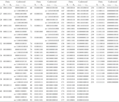
For illustration, the mapping relationship between data and codewords of a rate 3/4 code satisfying (keven1 =1,k1odd= 2,k=4) constraint is given inTable 2. The data to codeword mapping for a rate 8/11 code satisfying (k1even = 1,kodd1 = 2,k=7) constraint is listed inTable 3.
5. Power Spectral Density
In DVD systems the power spectral density at low frequency, referred to as the low-frequency content, of the encoded data sequences should normally be maintained as low as possible to alleviate interference with pilot and focus servo signals. For example, in addition to satisfying the (2, 10) constraint, the 8/16 EFMPlus code employed in the DVD system is also designed to achieve very low low-frequency content to reduce the interference between the written signal and the servo signal. Efficient low-frequency component suppression is a crucial criterion for the 8/11 (0,keven
1 =1,kodd1 =2,k =7) TMTR code rate. The low-frequency content is based upon the running digital sum (RDS)Zgiven by
Zi= i
j=−∞
Table3: Data to codeword mapping for the rate 8/11 (keven
1 =1,kodd1 =2,k=7) code.
Data Codeword Data Codeword Data Codeword Data Codeword
b1· · ·b8 c1c2· · ·c11 b1· · ·b8 c1c2· · ·c11 b1· · ·b8 c1c2· · ·c11 b1· · ·b8 c1c2· · ·c11
Table3: Continued.
Data Codeword Data Codeword Data Codeword Data Codeword
b1· · ·b8 c1c2· · ·c11 b1· · ·b8 c1c2· · ·c11 b1· · ·b8 c1c2· · ·c11 b1· · ·b8 c1c2· · ·c11
26 00011010 00001000110 68 01000100 00010100100 146 10010010 00110100010 230 11100110 01010101010 or 11001000110 or 11010100100 147 10010011 00110100100 231 11100111 10000000100 27 00011011 00001001000 69 01000101 00010100101 148 10010100 00110100101 232 11101000 10000000101 or 11001001000 or 11010100101 149 10010101 00110100110 233 11101001 10000000110 28 00011100 00001001001 70 01000110 00010100110 150 10010110 00110101000 234 11101010 10000001000 or 11001001001 or 11010100110 151 10010111 00110101001 235 11101011 10000001001 29 00011101 00001001010 71 01000111 00010101000 152 10011000 00110101010 236 11101100 10000001010 or 11001001010 or 11010101000 153 10011001 01000000010 237 11101101 10000010000 30 00011110 00001010000 72 01001000 00010101001 154 10011010 01000000100 238 11101110 10000010001 or 11001010000 or 11010101001 155 10011011 01000000101 239 11101111 10000010010 31 00011111 00001010001 73 01001001 00010101010 156 10011100 01000000110 240 11110000 10000010100 or 11001010001 or 11010101010 157 10011101 01000001000 241 11110001 10000010101 32 00100000 00001010010 74 01001010 00100000001 158 10011110 01000001001 242 11110010 10000010110 or 11001010010 75 01001011 00100000010 159 10011111 01000001010 243 11110011 10000011000 33 00100001 00001010100 76 01001100 00100000100 160 10100000 01000010000 244 11110100 10000011001 or 11001010100 77 01001101 00100000101 161 10100001 01000010001 245 11110101 10000011010 34 00100010 00001010101 78 01001110 00100000110 162 10100010 01000010010 246 11110110 10000100000 or 11001010101 79 01001111 00100001000 163 10100011 01000010100 247 11110111 10000100001 35 00100011 00001010110 80 01010000 00100001001 164 10100100 01000010101 248 11111000 10000100010 or 11001010110 81 01010001 00100001010 165 10100101 01000010110 249 11111001 10000100100 36 00100100 00001011000 82 01010010 00100010000 166 10100110 01000011000 250 11111010 10000100101 or 11001011000 83 01010011 00100010001 167 10100111 01000011001 251 11111011 10000100110 37 00100101 00001011001 84 01010100 00100010010 168 10101000 01000011010 252 11111100 10000101000 or 11001011001 85 01010101 00100010100 169 10101001 01000100000 253 11111101 10000101001 38 00100110 00001011010 86 01010110 00100010101 170 10101010 01000100001 254 11111110 10000101010 or 11001011010 87 01010111 00100010110 171 10101011 01000100010 255 11111111 10001000000 39 00100111 00001100000 88 01011000 00100011000 172 10101100 01000100100
or 11001100000 89 01011001 00100011001 173 10101101 01000100101 40 00101000 00001100001 90 01011010 00100011010 174 10101110 01000100110 or 11001100001 91 01011011 00100100000 175 10101111 01000101000 41 00101001 00001100010 92 01011100 00100100001 176 10110000 01000101001 or 11001100010 93 01011101 00100100010 177 10110001 01000101010
where{Xi} = {. . .,X−1,X0,X1,. . .} ∈ {−1, +1}represents the writing sequences. A lower RDS results in lower low-frequency content. The power spectral density of a sequence can be expressed as
H(w)= lim M→ ∞E
⎡ ⎢ ⎣ 1
2M+ 1
M
m=−M
Xme−jmw
2⎤
⎥
⎦. (14)
For a bounded RDS, that is,|Zi| = |
i
j=−∞Xj| ≤C <∞,
Cis a constant, and theDCcontent is then given as
H(0)= lim M→ ∞E
⎡ ⎢ ⎣ 1
2M+ 1
M
m=−M
Xm
2⎤
⎥
⎦≈0, (15)
0011000011 1
1 132
387 1011010101 1000100100
Main table
0000000100
0011000010 Substitute
table
262 131
β
β Sequence Sequence
0 0
0
0 . . .
. . .
. . .
. . .
. . .
. . .
X X
Figure4: Codebook of rate 8/11 (keven
1 = 1,kodd1 = 2, 7) TMTR
code.
10−4 10−3 10−2 10−1
−50
−45
−40
−35
−30
−25
−20
−15
−10
−5 0 5 10
Frequency
PSD
(dB)
EFMPlus code
8/11 TMTR code 3/4 TMTR code
Figure5: Power spectral density.
The PSD of both EFMPlus code and (0,keven
1 =1,kodd1 = 2) TMTR code can be computed using the fast Fourier transform (FFT)
H(kws)∼=
∞
n=1
XnWN(k−1)(n−1), (16)
whereWNk =e−j(2kπ/N), ws=2π/N.
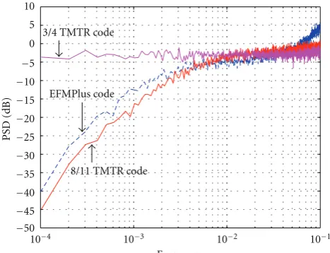
Figure 5depicts the power spectral density (PSD) versus the normalized frequency for the 8/16 EFMPlus code, the rate 3/4 (0,keven1 =1,k1odd =2,k =4) TMTR code, and the 8/11 (0,k1even=1,k1odd=2,k=7) TMTR code with method of enumerative, respectively. As shown, at frequency of 10−4, the PSDs for both EFMPlus and TMTR codes are−40 dB, −4 dB and−45 dB, respectively. The result indicates that the 8/11 (0,keven
1 = 1,kodd1 = 2,k = 7) TMTR code achieves
{uk}
{uk}
decoder
Optical recording channel
AWGN
EPRII equalizer User data
decoder User data
Viterbi detector encoder
8/11 TMTR 8/11 TMTR
Figure6: Optical recording system model.
a lower low-frequency content (with 5 dB lower) than the EFMPlus code. In Figure 5, we notice that the rate 3/4 (0,keven1 =1,k1odd=2,k=4) TMTR code has only−4 dB at frequency of 10−4and it is not suitable for optical recording systems, although it has a higher code rate compared to the 8/11 (0,k1even=1,kodd1 =2,k=7) TMTR code.
6. Simulation Results
The superiority of the rate 8/11 (0,k1even = 1,k1odd = 2) TMTR code over the EFMPlus code is also demonstrated on error performance through a computer simulation on the EPRII optical channel of the form P(D) = (1 +D)3.
Figure 6depicts the optical recording system for simulation. An 8-state transition diagram, as depicted in Figure 7(a), can describe the EPRII optical channel. During simulation, a Gaussian optical recording channel was assumed with impulse responsem(t) given by
m(t)= √2 πST exp
−
2t ST
2
, (17)
where S represents the user information density. T is the channel bit period assumed to be one (T =1) for uncoded systems in simulation. The optical recording channel is then corrupted with the additive white Gaussian noise (AWGN), and at receiver an ideal EPRII equalizer is employed to equalize the optical channel in the form ofP(D)=(1 +D)3. The Viterbi detector is then employed on the 8-state trel-lis diagram of the EPRII optical channel, to recover binary-recorded data from the equalized and sampled output. Note that for the EFMPlus-coded EPRII channel the 8-state trellis diagram can be reduced to a 6-state trellis diagram due to the (2, 10) constraint, as shown in Figure 7(b), while for the TMTR-coded EPRII channel the 8-state trellis diagram is still required with some branches deleted as depicted in
000 100 010 110 001 101 011 111
000 100 010 110 001 101 011 111 0/0
1/1 0/3 1/4 0/3 1/4
0/4 1/5 0/4 1/5 0/7 1/8
0/0 1/1 0/3 1/4 0/3 1/4
0/4 1/5 0/4 1/5 0/7 1/8 0/1
1/2 0/6
1/7
0/1
1/2 0/6
1/7
(a)
0/0 1/1 1/4 0/1
0/0 1/1 1/4
0/1
1/7 1/7
0/4
0/4
0/7 0/7
1/8 1/8
000 100 110 001 011 111
000 100 110 001 011 111
(b)
0/1
1/2 0/6
1/7
1/2 0/6
1/7 0/0
1/1 0/3 1/4 0/3
1/5 0/4 1/5 0/7 1/8
0/0 1/1 1/4 0/3
0/1 1/5 0/4 0/7 1/8
Odd Even
000 100 010 110 001 101 011 111
000 100 010 110 001 101 011 111
(c)
Figure7: Trellis diagram. (a) EPRII channel. (b) EFMPlus-coded EPRII channel. (c) TMTR-coded EPRII channel.
This is because both coded EPRII systems have a coding gain of 3 dB when these modulation codes are considered in the 8-state trellis diagram of the EPRII system during detection. This leads to a coding gain of 3 dB. As also can be seen in this figure, the TMTR-coded EPRII system improves the EFMPlus-coded EPRII system by approximately 1 dB in bit error rate. The coding loss of the EFMPlus-coded EPRII system is due to the bit rate loss.Figure 9shows the signal to noise (SNR) required to achieve a bit rate error of 10−5, as a function of user density, at a rate of 8/11 (0,keven
1 =1,k1odd= 2) TMTR code and a rate of 8/16 EFMPlus code, applied to an EPRII optical channel.Figure 9shows how the TMTR code provides little coding gain at user densities below 1.2 but increases coding gain at higher densities. At a user density
ofS = 2.0, the TMTR code on the EPRII optical channel provides nearly 2.7 dB of coding gain above the rate of 8/16 EFMPlus code on the EPRII optical channel. Therefore, from the performance comparison made in Figure 9, it can be seen that even a greater improvement in coding gain could be achieved for TMTR-coded EPRII system at higher user densities.
7. Conclusion
4 5 6 7 8 9 10 11 10−6
10−5
10−4
10−3
10−2
10−1
SNR (dB)
BER
Uncoded EFMPlus code
TMTR code for enumerative method
Figure 8: Error performance of TMTR-/EFMPlus-coded and uncoded EPRII systems.
0.8 1 1.2 1.4 1.6 1.8 2 7
8 9 10 11 12 13
User density
SNR
(dB)
EFMPlus code
TMTR code for enumerative method
Figure9: The SNR in dB required to achieve a 10−5BER versus user
density.
8/11 (keven
1 = 1,kodd1 = 2, 7) TMTR code is found. This code can achieve lower power spectral density at low frequencies compared to the EFMPlus code. In addition, computer simulations reveal that the rate 8/11 TMTR code outperforms the EFMPlus code in error performance when applied to partial response optical recording channels.
References
[1] K. A. S. Immink, “EFMPlus: the coding format of the multimedia compact disc,” IEEE Transactions on Consumer Electronics, vol. 41, no. 3, pp. 491–497, 1995.
[2] J. Moon and B. Brickner, “Maximum transition run codes for data storage systems,”IEEE Transactions on Magnetics, vol. 32, no. 5, pp. 3992–3994, 1996.
[3] B. E. Moision, P. H. Siegel, and E. Soljanin, “Distance-enhancing codes for digital recording,”IEEE Transactions on Magnetics, vol. 34, no. 1, pp. 69–74, 1998.
[4] W. G. Bliss, “An 8/9 rate time-varying trellis code for high density magnetic recording,”IEEE Transactions on Magnetics, vol. 33, no. 5, pp. 2746–2748, 1997.
[5] K. K. Fitzpatrick and C. S. Modlin, “Time-varying MTR codes for high density magnetic recording,” inProceedings of the IEEE Global Telecommunications Conference (GLOBECOM ’97), pp. 1250–1253, Phoenix, Ariz, USA, November 1997. [6] B. Nikoli´c, M. M.-T. Leung, and L. K.-C. Fu, “Rate 8/9 sliding
block distance-enhancing code with stationary detector,”IEEE Transactions on Magnetics, vol. 37, no. 3, pp. 1168–1174, 2001. [7] R. D. Cideciyan and E. Eleftheriou, “Codes satisfying maxi-mum transition run and parity-check constraints,” in Proceed-ings of the IEEE International Conference on Communications, pp. 635–639, June 2004.
[8] I. Demirkan and Y. X. Lee, “The combined constraints for perpendicular recording channels,”IEEE Transactions on Magnetics, vol. 42, no. 2, pp. 220–225, 2006.
[9] T. L. Poo and B. H. Marcus, “Time-varying maximum transition run constraints,”IEEE Transactions on Information Theory, vol. 52, no. 10, pp. 4464–4480, 2006.
[10] H.-F. Tsai and Y. Lin, “Turbo decoding for a new DVD recording system,”IEEE Transactions on Consumer Electronics, vol. 51, no. 3, pp. 864–871, 2005.
[11] R. D. Cideciyan, F. Dolivo, R. Hermann, W. Hirt, and W. Schott, “A PRML system for digital magnetic recording,”IEEE Journal on Selected Areas in Communications, vol. 10, no. 1, pp. 38–56, 1992.
[12] R. Karabed and P. H. Siegel, “Matched spectral-null codes for partial-response channels,”IEEE Transactions on Information Theory, vol. 37, no. 3, pp. 818–855, 1991.