UNIVAC~I
VotaA-oRfht
¥OM
01958, 1959 • SPERRY RAND CORPORATION
~ID ... 7I.rur.L ~
Table
Of Contents
ELEMENTS OF THE UNIVAC DATA AUTOMATION SYSTEM
Input-Output Units . . . . The Univac Central Computer . . . .
The Memory Uni t . . . • . . . The Control Uni t . . . . The Ari thmetic Uni t . . . .
PAGE
1
7
10
12
15
16
I I INTRODUCTION TO CODING
18
Arithmetic Instructions - List A... . . . .... 20
Illustrative Example... . ... ... ... ... .. . . 27
Student Exercises . . . 29
Arithmetic Instructions - List B " ... ... ... .... .... ... ... .... 29
The Decimal Point . . . 32
Rule for Addition and Subtraction.... .. . . ... . .. 32
Rule for Multiplication . . . 33
Rule for Division... . ... ... .. .. .... ... ... . . 33
Student Exercises... 34
The Control Unit . . . 35
Transfer of Control Instructions ... ... .... ... ... ... 36
Illustrative Example... ... ... ... ... 40
Student Exercises . . . 42
III
INTRODUCTION TO FLOW CHARTS
44 I llustrati ve Example . . . 50Studen t Exercises . . . • . . . 52
IV
MODIFICATION OF INSTRUCTIONS
55
I tera ti ve Coding . . . 59PAGE
IV
MODIFICATION OF INSTRUCTIONS
(con't.)
Illustrati ve Example ...•... 65
St uden t Exercises . . . 68
Function Table Look .. Up . . . 68
Illustrative Example ... '... 68
Function Table Look-Up in Flow Charts ... ... 70
Shi ft Instructions ...•... 71
Student Exercises . . . 76
v
ITEM PROCESSING
77 The Item .. ... .... ... ... ... ... ... 77The Field . . . 77
Representing Fields on Flow Charts. ... ... ... ... 78
Illustrative Example. ... ... ... .... ... ... . 79
Working Storage . . . 81
Item Registers . . . 83
Student Exercise . . . 85
Field Selection Instructions ... ~.. ... 86
Illustrati ve Example . . . 87
Student Exercises . . . 88
VI SUBROUTINES AND VARIABLE CONNECTORS
90 Conunon Subroutines . . . '90Illustrati ve Example . . . 90
Variable Connectors . . . 98
Student Exercise . . . 103
Subroutines . . . 104
VI I DETAILED DESCRIPTION OF INSTRUCTIONS
106 Transfer of Control Instructions ...•... 106Shift Instructions ...•...•... 108
Multiword Transfer Instructions . . . 108
Ari thmetic Instructions . . . 109
Overflow . . . 112
Undesi red Overflow . . . 120
PAGE
VI II
INPUT - OUTPUT
122123 125 126
IX
X
Character Representation
The Uni servo . . . . • . . . Buffering and Backward Read ... . Tape Instructions . . . . Tape Instructions on Flow Charts . . . . Sentinels . . . . The Instruction Tape . . . . Servo Del ta . . . < • • • • • • • • • • • • • • • • • • • • • • • • • • • • • • • • • • •
Illustrati ve Example . . . .
Studen t Exerci se ... 0 • • • • • • • • • • • •
EFFICIENT USE OF BUFFERS
Presele ction ... 0 • • • • • • • • • • • • • • • • • • • • • • • • • • • • • • • • • • • • 0 • 0 • Illustrative Example ... -... 0 • • 0 • • • • • • • • • • • • • • • • • • • • • • • • • Student Exercise . . . o • • • • • • 0 0 • • Standby Block Method 0 • • • • • • • • • • • • • • • • • • • • • • • • • • • • • • • • • • • • • • • • Student ExerciseSUPERVISORY CONTROL PANEL OPERATIONS
127 131 131 132 132 133 140 142 143 143 150 150 152 153 The 10m Instruction ... 0 • • • • • • • • • • • • 0 • • .. • • • • • • • • • • • • • • • • 154Condi tional Transfer Breakpoints • . . . 0 154 Printing from the Supervisory Control Panel ... 0 0 0 • • • • • 0 . . . . 155
The All Conditional Transfer Breakpoint Selector Button 0 . 0 0 . . 156
Interrupted Operation ... ... . . . . . .... . . .. .157
Other Breakpoints ... ... . . . . ... . . . . . . .. 158
Manual Alteration of Instructions in the Memory . . . 158
The Fill Operation . . . 158
SCICR . . . .. . . .. . . . . . .. . . .. . . . 159
Generating Data.. ... ... .. .... ... .... ... 159
Debugging Procedure . . . 159
The Empty Opera tion ... '. . . . 160
Memory Dump .... ... . . . .. . . . . . . . . .. ... 160
Veri fying the Output ... .... . . . . . . . . 161
XI
X II
XIII
PREPARATION AND DISPOSITION OF DATA
Keyboard to Tape Recording . . . . . Univac Uni typer . . . . Univac Veri fier . . . . Card-To-Tape R'ecording . . . • . . . • . . .
Univac
80
Column Card-to Tape ConverterPAGE
163
163
163
164
165
165
Univac
90
Column Card-to Tape Converter . . . • .168
Paper to Magnetic Tape Recording . . . '. . . . . . . . ..
169
Uni vac High -Speed Prin ter . . .
169
Tape to Punched Cards . . . •
171
Magnetic to Paper Tape . . .
172
OPERATIONAL ROUTINES
173
Ta pe Summary . . . • . . . • , .•.• -..174
Table Look Up . . . • . . . • . . . • . . . • . . .
178
Explosion Calculation.... . ... ... ... . . .... ...
181
INSURING ACCURACY OF PROCESSING
187
Operator Accuracy . . . • . . . • . . '.189
Re run . . . .. ... . . . . . . . . . . .. ... . . . . . . . . . . . . . . . . . .
189
Computer Accuracy . . . .. . . . . . .. . . . .
189
Type of Failures . . . .... . . . . . . . . . . .. . . . . . . . .
190
Error Detection . . .
190
Programmed Error Detection Diagnostic Routines . . .
190
Duplicate Runs . . .
191
Programmed Checks . . .
191
Bui 1 t in Checks . . .
192
Built in Checks of the Univac Central Computer . . .
192
Odd Even Check . . .
192
Duplicated Circuitry... ... . ...
193
chapter
1
Elements of the Univac
Data A.utomation System
INPUT-'"
PROCESSING-...
OUTPUT-'"
FIGURE 1·1
•
READ THE FIRST INYENTORY STOCK NUMBER
IS THERE A SALES
. . _ _ _ _ _ ...
..
~ ITEM FOR IT? WRITE THE.... I NYENTORY
READ THE NEXT ONE
.4
~YES
NO
. -... tJIQUANTITY IN THE~---~ NEW COLUMN
SUBTRACT THE SALES QUANTITY FROM THE IN YEN
T-ORY QUANTITY
,
IS THIS THE LAST I NYENTORY
STOCK NUMBER?
~ ~
. .
- - - -. .
~~No~~I~YE~S~~
PUT THE LE D GE R
AWAY
FIGURE 1·2
: SUBTRACT THE SALES QUANTITY
Thus, the clerk must be able to perform arithmetic; FROM THE I N V E
NT-FIGURE 1-3
he must be able to make logical decisions;
FIGURE 1-4
he must be able to remember information;
READ THE FIRST INVENTORY STOCK NUMBER
IS THERE A SALES ITEM FOR IT?
YES NO
ORY QUANTITY
(S THERE A SALES ITEM FOR IT?
NO
WRITE THE INVENTORY _ _ .alQUANTITY IN THE
~~~~----.--~ NEW COLUMN
READ THE NEXT ONE
SUBTRACT THE SALES QUANTITY FROM THE
INVENT-ORY QUANT I TY
FIGURE 1-5
and he must either execute the steps in the sequence shown or do something logically equivalent to this sequence of step's.
....oIIIIl
THEN, " DO THIS
+
THEN....
r DO OR
THIS
I
THIS~~
THEN, DO THIS
THEN, DO THIS
..
~DO THIS
FIGURE 1·6
This example involves six elements.
1 Input 2 Arithmetic
3 Logical Decisions
4 Memory 5 Control 6 Output
FIRST, DO THIS
THEN,
..
DO THIS,..
~ ~
,
THEN
OR NOW, STOP
I
THIS~
STOCK SOURCE DOCUMENT
INVENTORY
UNITYPER
FIGURE 1·7
Instead of a sales form, a sales tape is produced da~ly, also by the Unityper. In-stead of the clerk, the Univac Central Computer does ~he processing.
UNIVAC
PROCESSING
FIGURE 1·8
The inventory tape is read by means of a tape handling mechanism called a Uniservo.
INVENTORY TAPE
UNISERVO
UNIVAC
FIGURE 1-9
The sales t.ape is read from another Uniservo.
The clerk brought the inventory up to date by writing a new column in the ledger. The Central Computer brings the inventory up to date by writing an updated inven-tory tape on a third Uniservo.
In this application the Central Computer requires three Uniservos - two for reading and one for writing. Reading and writing requirements vary from application to application. To provide maximum flexibility, the Central Computer has access to a bank of 10 Uniservos, any of which can be used for reading or writing.
In the manual solution, the column the clerk writes in the ledger on anyone day, that is, the inventory output, becomes the inventory input on the next day. The sales form continues to originate each day from outside the data processing sys-tem.
Similarly, 10 the Univac System, the updated inventory tape written one day
be-comes the next day's inventory tape, while the sales tape continues to originate each day from outside the system. Once the inventory tape has initially been uni-typed it need never be uniuni-typed again, since it is kept up to date by the Central Computer.
DATA PROCESSING SYSTEM
SALES TAPE
UNIVAC
UNITYPER
UPDATED
SOURCE DOCUMENT
BANK OF UNISERVOS
I NVENTORY TAPE
FIGURE 1-10
INPUT OUTPUT UNITS
In many cases, input data does not come, and output data is not desired, in tape form. The Univac Data Automation System includes several input units to convert data from some other form to tape, and output units to convert tape data to some other form.
INPUT UNITS
The Unityper has already been discussed as an input unit.
7
The Univac Card-to-Tape Converter converts data punched on cards to tape.
CARD-TO-TAPE CONVERTER
FIGURE 1·11
The Univac PTM converts data punched on paper tape to magnetic tape.
FIGURE 1·12 PAPER-TO-MAGNETIC TAPE CONVERTER
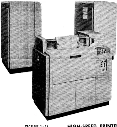
OUTPUT UNITS
The Univac High-Speed Printer.
FIGURE 1-13 HIGH-SPEED PRINTER
The Univac Tape-to-Card Converter .
FIGURE 1-14 . TAPE -TO- CARD CONVERTER
The Univac MTP converts magnetic to paper tape.
FIGURE 1·15 MAGNETIC -TO-PAPER TAPE CONVERTER
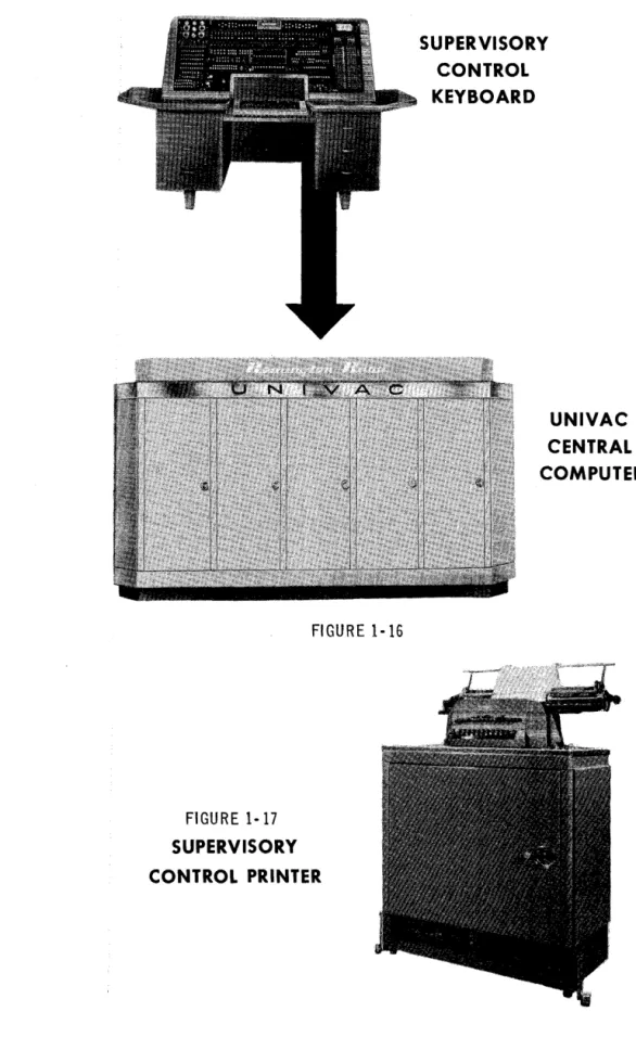
KEYBOARD INPUT OUTPUT
Besides using tape, the Central Computer can also accept and produce small volume data directly by means of a keyboard and a typewriter.
The Central Computer accepts data directly from an operator's key strokes on the Supervisory Control Keyboard.
The Central Computer produces printed data directly on the Supervisory Control Printer, which is a modified typewriter.
THE UNIVAC CENTRAL COMPUTER
To satisfy the requirements of an automatic data processor, the Univac Data Auto-mation System must not only be able to accept input and produce output, but must also incorporate the other functions of a data processor, memory, control, arithme-tic and logical decision.
FIGURE 1-16
FIGURE 1-17
SUPERVISORY CONTROL PRINTER
,
,
SUPERVISORY CONTROL KEYBOARD
These functions are performed by the Central Computer of the Univac System. The memory function is performed by the Central Computer's memory unit; the control function, by the Central Computer's control unit; and the arithmetic and logical decision functions, by the arithmetic unit.
THE MEMORY UNIT
In the manual system described above, all information necessary to the processing is made available to the clerk in some form.
1. The stock number and inventory and sales quantities are on the ledger page and sales form.
2. The date of the current updating is on a calendar.
3. The instructions for updating the inventory are in a procedures manual.
The above information can be classified as:
1. data,
2. constants,
3. instructions.
Similarly, in the Univac System, all necessary information is made available to the Central Computer; the data, on an input tape; the constants and instructions, on an instruction tape.
However, to have the information available is not sufficient for the clerk to do the processing. While processing, the clerk must remember the information bearing on the current processing step. Moreover, the clerk must remember the results of any calculation done at least until he writes the results in the ledger. Similarly the Central Computer must "remember" the data, constants and instructions that it reads from tape, and must Ct remember" the results of calculations until it writes
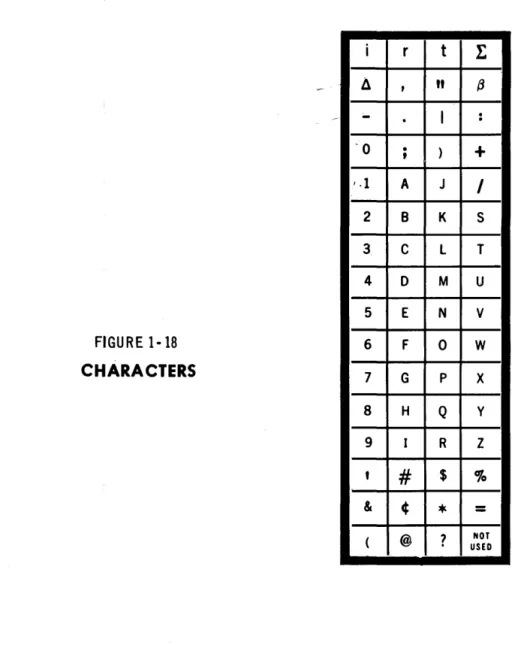
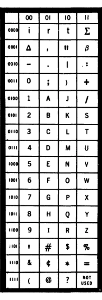
them on the output tape. The Central Computer ccremembers", or stores, informa-tion in its memory unit. The memory is divided into cells. Any cell can be used to
store data, constants or instructions. The 63 characters used to represent informa-tion are shown below.
FIGURE 1-18
CHARACTERS
i
Il --0 1.1 2 3 4 5 6 7 8 9,
& ( r,
.
.
,
A B C 0 E F G H I#
¢ @t
t
"
(3I
.
.
)
+
J
I
K S
L T
M U
N V
0 W
P X
Q y
R Z
$
%
*
=
?
USED NOTOne cell can store one ccword", a word being any permutation of twelve characters. The following are examples of words.
JOHN~J~JONES JUNE~I 0~1926
0123'1-5678901 AOOIOOC00200
The positions of the characters in a word are named as follows.
-~
,
FIRST DIGIT POSITION OR SI'GN POSITION SECOND OR MOST SI'GNIFICANT DI'GIT POSITION THIRD DIGIT POSITION
FOURTH DIGIT POSITION FIFTH DIGIT POSITION SIXTH DIGIT POSITION SEVENTH DIGIT POSITION EIGHTH DIGIT POSITION NINTH DIGIT POSITION TENTH DIGIT POSITION ELEVENTH DIGIT POSITION
TWELFTH OR LEAST SI'GNIFICANT DIGIT POSITION
I I I I I I I I I I I I I
FIGURE 1-19
If a word represents an algebraic quantity, the sign of the quantity must be in the sign position. A plus sign is represented by a zero; a minus sign, by a minus.
FIGURE 1- 20
WORD AS A SIGNED QUANTITY
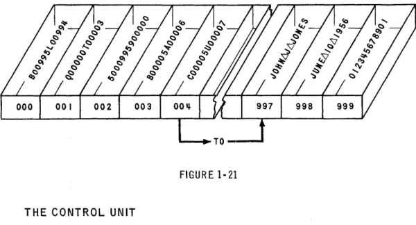
The memory Size is 1000 cells. For the purpose ·of referring to word s in th e memory, each cell is given a distinct address. A word in the memory is distin-guished from all other words in the memory by the address of the cell in which it is stored. The cells are addressed consecutively from 000 to 999.
14-Once a word has been transferred to a cell, it remalnS In that cell until another word is transferred to take its place.
Figure 1-21 is a stylized version of the memory unit storing instructions, data and constants.
FIGURE 1-21
THE CONTROL UNIT
The code for an instruction IS represented in SIX characters. Consequently, two instructions, called an instruction pair, are represented in one word.
FIGURE 1 .. 22
INSTRUCTION PAIR
LEFT HAND INSTRUCT I ON
(I I
i
I
WORD
The function of the control unit is to select, in the proper sequence, each instruc-tion in the memory, interpret it and execute it. Instrucinstruc-tions are selected in pairs, one word, at a time. The left hand instruction (LHI) is executed, and then the right hand instruction (RHI).
The selection of instruction pairs is performed in a sequential manner. That is, if the instruction pair just executed is in cell 019, the next pair to be executed is in cell 020.
Initially the control unit begins the sequential execution of instruction pairs with the pair in cell 000. Thus, to have instructions executed in sequence, it is only necessary to represent the first instruction in the LBI of the word In cell 000; the second in the RBI of the word in cell 000; the third in the LHI of cell 001; and so on.
CONTROL
FIGURE 1·23
THE ARITHMETIC UNIT
LEFT HAn
IUTRUCTlOIi
RlaHT HAND
I UTRUCT I 011
1ST INSTRUCTION INSTRUCTION INSTRUCTION INSTRUCTION 5TH INSTRUCTION 6TH INSTRUCTION
The arithmetic unit has characteristics In common with a desk calculator in that it contains an adder to produce the sum or difference of two words, a multiplier the product, and a divider to produce their quotient. In addition, to enable the Central Computer to make logical decisions, the arithmetic unit contains a com-parator, which inspects two words to determine their equality or relative magnitude.
To operate on a word in the memory, the Central Computer must transfer the word to the arithmetic unit. To provide storage for such words, the arithmetic unit con-tains four registers named A, X, Land F. The arithmetic registers are identical to memory cells except that they are auxiliary to the memory. The registers serve the arithmetic unit in the same way as dials serve
a
calculator, each registerstor-ing either a word to be operated on or the result of an operation.
Figure 1-24 is a stylized version of a portion of the arithmetic unit.
ARITHMETIC UNIT
FIGURE 1 ·24
FROM MEMORY
TO THE
£t----401~--4f---40--... MEMORY
SI6UL
- _ e . TO
co_nOL
U_I T
The memory, control and arithmetic units and their interrelations are shown here: (The 60 word registers I and 0, used for input and output and the multiword regis-ters V and Y will be described in detail in a later chapter).
chapter
2
Introduction to Coding
The preparation of a problem for its solution by The Univac Data Automation Sys-tem is called programming. Programming is done in three steps.
1. Process Charting - The layout of the data processing system 1fi terms of input, output and processing.
2. Logical Analysis - The analysis of the processing into a sequence of ct small" logical steps.
3. Coding - The translation of the logical analysis into instructions.
PROCESS CHARTING
Figure 2-1 is a process chart.
In this manual all problems requiring logical analysis and coding are given in dis-cursive form. All the problems specify three things - input, processing and output and could be put in process chart form which is tile usual basis for analysis and
cod-ing.
PROCESS CHART
FIGURE2-1
CODING
I
I
I
I
I
I
I
I
I
I
I
L
UP DATE ON HAND AMOUNT
~
INPUT
~PROCESSING
~OUTPUT
Computers usually perform a function in a series of operations. Each operation is executed under the influence of an instruction. An instruction specifies at least two things.
1. the opel'ation to be performed. 2. the data to be operated on.
The data is usually specified in terms of the storage in which the data is to be found. For example, the data might be specified in terms of the address of the cell in which it is stored.
A computer might perform the function of adding two quantities together and record-ing the sum in three operations.
1. Select one quantity.
2. Add the second quantity to the first.
~. Record the sum.
If one quantity is in cell 880; the other, in 881; and if the sum is to be stored in cell 882; the instructions to cause the computer to do the above operations might be:
1. BRING 880 2. ADD 881 3. CLEAR 882
where BRING, ADD and CLEAR are code for the operations to be done; and 880, 881 and 882, the addresses of the cells in which the data is stored.
In the central computer of the Univac Data Automation System an instruction con-sists of six characters, named as follows.
FIRST SECOND THIRD FOURTH FIFTH
INSTRUCTION DIGITS FIGURE 2- 2
SIXTH
The first and second instruction digits indicate what operation is to be performed; the fourth through sixth digits, the address of the word affected by the operation. The third digit is normally a zero. (This digit is ignored in the execution of the 'instruction. )
l ________
J
l'---r-!
---",J
The instruction500880
tells the central computer to perform the operation indicated by ct 50" on the word
in cell 880.
ARITHMETIC INSTRUCTIONS - LIST A
An urn" is used to symbolize the fourth through sixth instruction digits. Paren-theses are used to symbolize t t the contents of". The symbol
(m)
means "the contents of cell m". An "r" IS used to symbolize "register". The
( symbol
rA
means cCregister A". An arrow is used to symbolize ccis (are) transferred to". The symbol
means "(m) are transferred to rA".
To process data, the computer must read the data from tape and store it in the memory. There are instructions that, when executed, do the reading. These
10-structions will not be discussed at this time. Instead, reading data will be in-dicated by the words, cCRead Data".
INSTRUCTION OPERATION MNEMONIC
BOrn (m~rA, rX Bring
Transfer (m) to rA and rX, or bring (m) to rA and rX.
INSTRUCTION OPERATION MNEMONIC
COm Clear
Transfer (rA) to m. Transfer a word of zeros to rA} or clear rAe
One of the possible uses of these instructions is to transfer a word from one cell to another. If the word in cell 880 is to be transferred to cell 881, the sequence of instructions might be
B00880 C00881
INSTRUCTION OPERATION MNEMONIC
HOm (rA}----I~ .... m Hold Transfer (rA) to m.
The mnemonic is to hold (rA) after the trans~er to memory. The HOm instruction differs from the COm instruction only in that (rA) remains unchanged.
880
881 rA rX
8
o o
8
/0/1/2/3\1I/5/6/7/8/9/0/1j 10/2/3\11/5/6/7/8/9/0/1/2/
FIGURE 2- 4
INSTRUCTION
JOm
8
o
I!IDSEJDIIDDDI1BD
880
I
0 \2\3\ 11\5/6/7/8/9/ 0/1 /2/ 881I
0 /3/ 11/5/6/7/8/9/ 0 /1 /2 /3/ rAI
0 / 11/5/6/7/8/9/ 0 /1 /2/3 /11 / rXc
o o
8 8 1
880
881 """'''''''''''''''',+10/0/0/0/0/0/0/0/0/0/0/0/
10/1/2/3/11/5/6/7/8/9/0/1/ rA rX
OPERATION
(rX)~m
Transfer (rX) to m.
One of the possible uses of these instructions is to duplicate the contents of a certain cell in several other cells. If the contents of cell 880 are to be duplicated in cells 881, 882 and 883, the instructions mi.ght be
B00880 H00881
J
00882 C00883or: B00880
J
00881J
00882J
00883H
or: B00880 1100881 H00882 H00883
etc.
INSTRUCTION OPERATION
AOm (m)~rX; (rA) + (rX)---...rA Add (rA) and (m), and transfer the sum to rA.
22
MNEMONIC
B
o o
8
8
880
8Bl
IAIAIAIAIAIAIAIAIAIAIAIAI IBIBIBIBIBIBIBIBIBIBIBIBI
B82 I c I c I c I c I c I c I c I c I c I c I c I c I
883 I DID I DID
I
DID I DID I DID I DID IrA rX
J
o
o
8
8
8BO IAI AI AI AI AI AI AI AI AI AI AI AI
881 IAI AI AI AI AI AI AI AI AI AI AI AI
BB2 IAIAIAIAIAIAIAIAIAIAIAIAI . . . . BB3 I DID 1 DID I DID 1 DID I 0 I DID I D I
rA
FIGURE 2-5
880
o
IBtBIBIBIBIBIBIBIBIBIBIBI 881Iclclclc(clclclc)clclclcl 882
I D ID I DID I DID I DID
I
DID I DI DI
883I E I Eli! I E I E I E I E I E) E I E I E I E I rA IFIFIFIFlrfFIFIFIFIFIFIFI rX
2
_.'1
IAIAIAIAIAIAIAIAIAIAIAIAI A I A I A I A 1 A I A I A 1 A I A 1 A I A 1 A I 880 BBIIe/ c I c I c Ie/ c I c I c I c Ie/ c I c I 882
IDIDIDlolDIDIDlolololDIDI BB3
IAIJIAIA/AIAIAIAIAIAIAIAI ~ rX
c
o o
8
I8
I
3
IAIAIAIAIAIAIAIAIAIAIAIAI B80
I
AI
A I AI
A / A I A I A I A I A I A I A fA I 881IAIAIAIAIAIAIAIAIAIAIAIAI B82
_ • • 1 AlAI AI AI AI AI AlAI AI AI AlAI 883
""""""""11"""
0 I 0 I 0 I 0 I 0 I 0 I 0 I 0 I 0 I 0 I 0 I 0 I rAIAIAIAIAIAIAIAIAI~ rX
The mnemonic is to add (rA) and (m). The computer executes the AOm instruction as follows. (m) are transferred to rX. (rA) and (rX) are added. The sum is trans-ferred to rA.
To add the contents of cell 880 to the contents of cell 881 and store the sum in 882. the sequence of instructions might be
880
881
B00880 A00881 C00882
882 I 0 131 ~ 151 61 71 sl 91 0 II 12131
rA rX
c
or
o
o
8
880 101112131~lsI6\7IsI910\11 881 10 12131 ~ Isl6171s191 0 II 121
682 10131s18101211116171911131
rX
I
0 1213111 1516171819 I 0 II 121ADDER
8
2
I I I I I I I I I I I I
B00880 A00881 H00882
if it is desired to preserve the sum in rA.
860
10 12131 ~ Isl6171s191 0 II 121 881
lo131~ls16171s191ol "2131 862
I 0 I ~ I sl 6171s191 0 II 1213 I ~ I rA
1 0 lsi 6171s191 0 II 12\31 ~ lsi rX
8
loll\2131~lsI617IsI910111
10 \2131
~
151617\s191 o}t12(~/
FIGURE 2-6
8
1
880
881
882
INSTRUCTION OPERATION
XOm (rA) + (rX)~rA
Transfer the sum of (rA) and (rX) to rA.
When executing the XOm instruction the computer ignores m.
One of the possible uses of the XOm instruction is to add the same number to a sum more than once. Assuming that a quantity is in cell 880, the sequence of instructions to build up three times the quantity might be
B00880 XOOOOO XOOOOO
B
I
0
I
0
I8
I
8
1
0
1880
rA rX
x
o o
o
o
o
FIGURE 2-7
25
o
lo111213141516171!l1910111 /01213141516171819101112/
101 0
I
0II
1210I
0I
0I
0II
121 0I
o o
o
8BO
rA rX
880
rA rX
o
I
0I
0I
UII
12I
0I
0I
0I
0II
121 0I
8801I_lItl
olo 10131610101010131610I
rAINSTRUCTION OPERATION MNEMONIC
SOm Subtract
Subtract (m) from (rA). Transfer the difference to rA.
The mnemonic is to subtract (m) from (rA). The computer executes the SOm in-struction as follows. Minus the (m) are transferred to rX. (rA) and (rX) are added. The sum is transferred to rA.
880
rX
lit lall
12131111 tiDII
1213111I
S
0 0
I
8
I
8
I
ADDER
0
I
101.0I
0 10I
0I
0I
0I
0I
0 11151 0I
FIGURE 2·8
SIGH CHANGER
880
rlt rX
If the contents of a cell are negative, minus the contents would be positive.
INSTRUCTION OPERATION
50m (m) ... SCP
Print (m) on the Supervisory Control Printer (SCP).
880
5
o o
8
8
o
ALPHAXXBRAVO
FIGURE 2· 9
INSTRUCTION OPERATION
90m Stop
Stop operation
In executing the 90m instruction, the computer ignores m.
ILLUSTRA TIVE EXAMPLE:
Reading the data stores the ON HAND quantity of a commodity in cell 880, the ON ORDER quantity in cell 881, and the EXPECTED REQUIREMENTS for the next 60 days in cell 882. Print (on hand) + (on order) - (required). (Data will frequently be stored in memory starting at cell 880 because of programming con-venience. Reasons for this will be described in a later chapter.)
LOGICAL ANALYSIS
1. Read the data.
2. Add the on order to the on hand. 3. Subtract the required from the sum. 4. Print the difference.
5. Stop.
CODING
000 READ
}
Read the dataDATA 001 B00880
}
Add the on order to the on hand A00881002 S00882 Subtract the required from the sum C00883
}
003 500883 Print the difference 900000 Stop
The following is a description of the thinking that might have accompanied this coding.
Since the computer executes instruction pairs by starting with the pair in cell 000
and moving sequentially through the instruction pairs following, the instruction pairs should be stored in logical sequence, starting in cell 000. Furthermore, since the computer executes the LHI of an instruction pair before the RHI, the first instruction of a pair to be executed should be coded as the LHI.
The logical analysis shows that the first step is to read the data. This step 1S
shown by writing "Read Data" in cell 000.
The next step in the analysis is to add the on order quantity to the on hand quantity. The computer will add two quantities if it is given an AOm instruction. But the AOm instruction adds those quantities stored in rA and m. The on hand and on order quantities are in cells 880 and 881. Before the quantities can be added together
one must be stored in rAe To store a quantity in rA, the BOrn instruction can be used. To store the on hand quantity in rA the LBI in cell 001 should be:
B00880
At the completion of the B00880 instruction the on hand quantity will be in rAe To add the on order quantity to (rA), the instruction needed is
A00881
which should be the RHI of cell 001.
After the execution of the AOm instruction the computer will have stored the sum of the on hand and on order quantities in rAe The next step is to subtract the re-quired quantity from the sum. This step calls for an SOm instruction where the minuend is in rA and the subtrahend is in the memory. This situation is present, so a S00882 instruction will subtract the required quantity from the sum of the on hand and on order in rAe
The next step is to print the difference. The 50m instruction prints the contents of a cell, but the difference is in rAe Therefore, the contents of rA must be stored in a cell. This storage can be done by means of the COm instruction. The cell specified by the COm instruction must not contain anything necessary to the execu-tion of the remainder of the coding. Cell 883 meets this requirement, and the in-struction could be C00883. The execution of this inin-struction transfers the differ-ence to cell 883. Then the execution of the instruction, 500883, will print the difference on SCP.
The last step is to stop the operation. The execution of a 90m instruction does this.
It is customary to draw a line under 90m instructions to separate the coding into related segments.
STUDENT EXERCISES
1. Reading the data stores a quantity In cell 880. Store the quantity in cells 881 and 882.
2. Reading the data stores two quantities in cells 880 and 881. Interchange the quantities.
3. Reading the data stores five receipt amounts In cells 880 - 884. Print the sum of the receipt amounts.
4. Reading the data stores four quantities, A, B, C and D, in cells 880 - 883. If
E = A·l+ B,
f
F = A + B - C:
G=A+f3 C+D
print E, F and G.
5. Reading the data stores four quantities, A, B, C, and D, in cells 880 - 883. If
R = 2A - B +
3
(C + D)print R.
ARITHMETIC INSTRUCTIONS - LIST B
INSTRUCTION OPERATION MNEMONIC
LOrn (m)____rL, rX Load
Transfer (m) to rL and rX, or load rL and rX with (m).
INSTRUCTION OPERATION
KOm (rA)--...rL; O~rA
Transfer (rA) to rL. Transfer a word of zeros to rAe
In executing the KOm instruction, the computer ignores m.
INSTRUCTION OPERATION MNEMONIC
POrn ~m} Precision
(rL) x (rX}-...rA [11 MSD], rX [11 LSD] Multiply
Multiply (rL) by (m). Transfer the 11 most significant digits of the product to rA; the 11 least significant digits to rX.
The execution of the POrn instruction produces a precise 22 digit product. The mnemonic is to precision multiply (rL) by (m). The computer executes the POrn instruction as follows. (m) are transferred to rX. Three times the absolute value of (rL) are transferred to rF. (The reason for this is described in a later chapter.) (rL) are multiplied by (rX). The 11 most significant digits of the product are trans-ferred to digit positions 2-12 of rA; the 11 least significant digits, to positions 2-12 of rX. The sign of the product is transferred to the sign positions of rA and rX.
INSTRUCTION MOm
OPERATION
(~)--+-rX; ] .~ -~_~Ir.,.,.,l.lE;;:
(rL) x (rX}--....rA [11 MSD rounded] , rX [11 LSD + .5 ]
MNEMONIC Multiply
Multiply (rL) by (m). Transfer the product to rA.
The execution of the MOm instruction produces an 11 digit rounded product in rA. The mnemonic is to multiply (rL) by (m). The computer executes the MOm instruc-tion in the same way as it executes the POrn instrucinstruc-tion. except that, after the operation associated with the POrn instruction is complete, five is added to the most significant' digit of (rX), and if a carry is produced, it is added to the least significant digit of (rA).
INSTRUCTION NOm
OPERATION
- (m)-. r X;
~!~fttfr!?t~"5)
{rL} x (rX) ... rA [11 MSD rounded], r X [11 LSD + .5]
MNEMONIC Negative Multiply
Multiply {rL} by minus (m). Transfer the product to rA.
The mnemonic is to negative multiply (rL) by (m). The computer executes the NOm instruction as follows. Minus (rX) are transferred to rX. The remainder of the
tion IS exactly as in the execution of the MOm instruction. The following figure
shows the difference in the effect of the execution of the POrn, MOm, and NOm instructions. GIVEN rA P0880: rA MOSSO: rA
N 0880:
o
8 II I 0I
0 I 0 I 0 1010 I 0 10 12 IIN ALL CASES
INSTRUCTION
DOm
rF
1217101010101010101010131 FIGURE 2·10
OPERATION
(m) ... rA;
rL
1019101010101010101010111
880
10 Jg 10 1010 10 10 10 10 10 I 0 II I
rX rX 10GIoioioioioioioioloIII rX 03101010101010101010111 MNEMONIC Divide (rA) • '(rL)~rA [rounded],
rX [unrouded]
Di vide (m) by (rL). Transfer the rounded quotient to rA and the unroundedquotient to rX. [(rL) must be larger in absolute value than (m)]
The execution of the DOm instruction produces an 11 digit rounded quotient in rA and an 11 digit unrounded quot.ient in rX. The mnemonic is to divide (m) by (rL). The computer executes the DOm instruction as follows: (m) are transferred to rAe (rA) are divided by (rL). The unsigned, unrounded, 12 digit quotient is transferred to rX. Five is added to the leas't significant digit of (rX) and the sum is transferred to rAe (rA) and (rX) are shifted right one digit position. The sign of the quo,tient is transferred to the sign position of rA and rX.
For example:
In executing 000101: 411522630566 +0000,0'005 \ 411522630571
h'f '1 " h d ' ,
S 1 t 1 P ace rig t an 1nsert s1gn
JI ,
rA rX
041152263057 041152263056
31
rL030000000000 101 012345678917
THE DECIMAL POINT
The computer fixes the decimal point between the sign and most significant digi~t
positions. Because every algebraic number begins with a sign followed by a decimal point, as far as the computer is concerned, every algebraic quantity lies between plus one and minus one, the largest being
+.99999999999-the smallest
-.99999999999
How can algebraic quantities of magnitude one or larger, or minus one or less, be represented? This problem is really no different in kind than the similar one pre-sented by an ordinary desk calculator. Like the computer, the calculator fixes the decimal point at some specific place, usually immediately after the least signi-ficant digit position. Yet operators have no difficulty in treating fractional quanti-ties on a calculator. Such quantiquanti-ties are handled as follows. All quantiquanti-ties are entered into the calculator as whole numbers, and decimal points are assumed in the numbers to create the fractional quantities. During the calculation the assumed decimal points are ignored. After the calculation is complete, the decimal point is assumed in the result according to certain rules. The same kind of solution applies to the computer. Decimal points can be assumed in a word wherever wanted. At the end of the calculation the following rules apply.
RULE FOR ADDITION AND SUBTRACTION
To add two words, or to subtract one word from another, the decimal point must be assumed in the same place in both words. The word that represents the sum will have the assumed decimal point in the same place as it is assumed in the words entering the calculation.
A carat indicates the assumed decimal point.
$3600.05 156.23
$3756.28
03600,,0500000 001562300000
"
037562800000
"
32
00000036001\05
000000015623
1\
000000375628
RULE FOR MULTIPLICATION
When multiplying one word by another, if the assumed decimal point is m digit positions to the right of the fixed decimal point in one word, and n positions to the right in the other, the product will have the assumed point m plus n positions to the right.
RULE FOR DIVISION
When dividing one word by another, if the assumed point is m positions to the right of the fixed point in the dividend, and n positions to the right in the divisor, the quotient will have the assumed point m minus n po~itions to the right.
For example, if
and then
A = OXXXXXXXXXXX
"
B = OXXXXXXXXXXX 1\
AB = OXXXXXXXXXXX
"
and A+ B = OXXXXXXXXXXX
"
m=4
n = 3
m-n = 1
J!J.h>....assumed l?oinLis. p. positigHs . to_the left, of-!he fixedj?~, i!~-=-p positiof!.s
~the right. The fact that assuming the decimal point p places to the right of the fixed point is equivalent to multiplying the word by lOP makes the proof of the above rules immediate.
For example
0,21200000000 031200000000
"
.312 (no assumption made)
.312 x 102 = 31.2 (where the assumption is p = 2)
When n and/or m are zero the above rules give the following results. If m and n are zero then m plus nand m minus n are zero. Thus, if in two words, the decimal point is assumed at the fixed decimal point, the assumed decimal point in the product or quotient of the words will be at the fixed point.
If n is zero, then m plusn and m minus n equal m. Thus, if the point is assumed m positions to the right of the fixed point in a given word, and is assumed at the the fixed point in a second given word; the product of the given words, and the quotient of the first word divided by the second, will have the assumed decimal point m positions to the right. For example, if
l ' \
A = OXXXXXXXXXXX
A
and B = OXXXXXXXXXXX
A
then
AB = OXXXXXXXXXXX
"
and A..;.
n
= OXXXXXXXXXXX"
STUDENT EXERCISES
m=9
n = 0
m + n =
9
m- n = 9
1. If A has the form O"XXXXXXXXXXX; and B, the form O"XXXXXXXXXXX; what is the form of AB and A -:- B?
2. If A has the form OXXXXXXXXXXX; and B, OXXXXXXXXXXX; what is the form
A. A
of AB and A -:- B?
3. If A has the form OXXXXXXXXX}X; and B, RXXXXXXXXXXX; what is the form of AB and A+B?
4. Reading the data stores three quantities of form
O"QQQQQQQQQQQ
in cells 880 - 882. Print the product of the quantities.
5. Reading the data stores
DATA
Quantity A Quantity B Quantity C Quantity D
If
E = AB
AB F = .9C
G
=
.9C AD _print E, F and G.
D
FORM
o,POAAAAAAAAA o,POBBBBBBBBB q,OOCCCCCCCCC O"OODDDDDDDDD
CELL
880 881 882 883
f \
6.
Reading the data stores. DATA FORM CELL
Income
o
I I I 11It!
10 0 0 880Number of Dependents OONNOOOOOOOO
1\ 881
Deductions other than OOQ~1\AAOOO 882
for Dependents
A deduction of $600 is allowed for each dependent. The tax is twenty percent of taxable income. Print the tax in form
OOOOOOTTTTATT
THE CONTROL UNIT
The function of the control unit 1S to select instructions from the memory and
execute them in proper sequence. The control unit is made up of three registers.
1. The Static Register (SR), a half word register. 2. The Control Register (CR), a one word register.
3. The Control Counter (CC), a one word register.
To execute an instruction the computer must transfer the instruction to th(! Static Register, the only place in the computer where an instruction can be interpreted. Since the computer can only execute one instruction at a time, only one instruction can be stored in SR at anyone time. Thus, SRis built with a six character capacity.
The computer transfers instructions from the memory to the control unit one word at a time and uses the Control Register to store the instruction pair while the instructions are waiting to be executed.
Having transferred an instruction pair from a given cell to CR, the computer must store the address of the cell immediately following the given cell in order that, when the instruction pair in CR has been executed, it will know in what cell to find the next pair. The computer stores this address in the three least significant digits of the word in the Control Counter.
In short,
1.
SR
is an interp~C!~l.!!... devi£,e,2. CR contains the current instruction pa!L
3. (:~ contains the address o~,.next ill.s.ttuctionpair.
In Univac the extraction and execution of instructions is performed in four steps which are identified by the first four letters of the Greek alphabet:
STEP DESCRIPTION
a
(:3
y
The right hand SiX digits of CC are duplicated in
SR. The memory address section of SR now con-tains the address of the next instruction pair.
The effector circuits of SR now cause the contents of the memory cell as specified by the address
section of SR to be duplicated in CR.
A one is added in the least significant digit posi-tion of CC (digit posiposi-tion 12).
The Left Hand Instruction now in CR is duplicated in SR, and being in SR causes the effector circuits to execute it: that is, interpret it as an instruction.
The Right Hand Instruction in CR is duplicated in SR, and executed.
The computer automatically steps through the cycle and then after completing the 8 step, begins on a. The important thing to note is that if CC
=
000000000000 initially, the computer executes the Left Hand Instruction found in memory cell 000, then the Right Hand Instruction in that cell. Then, LHI of cell 001, RBI of 001, LHI of 002, RHI of 002, etc. Also note that instructions are executed only when they are in S~ during stages y or 8.TRANSFER OF CONTROL INSTRUCTIONS
Having executed the instruction pair in cell ttk", it is sometimes advantageous for the next instruction pair to be in a cell other than cell ttk + 1 ". This breaking of the computer's sequential operation is called transfer of control.
INSTRUCTION OPERATION MNEMONIC
UOm 000000000 (CR~CC Unconditional
Trans-fer of Control Transfer control to m. Sequential operation is broken at cell k
and resumes at cell m.
The mnemonic is unconditional transfer of control to m, since the execution of the UOm instruction results in transfer of control regardless of the conditions present in the computer. The computer executes the UOm instruction as follows. CC con-tains the address of the next instruction pair. If the execution of the UOm instruction is to transfer control to m, the execution must transfer the address part of the UOm instruction to CC. Actually, the UOm instruction is executed by transferring the three least significant digits of (CR) to the three least significant digit positions of CC. This method of execution will achieve the purpose of the UOm instruction pro-vided that the address part of the UOm instruction is the three least significant digits. of the word in which the UOm instruction appears. In effect, this fact means that the UOm instruction should be coded as a RHI.
I
c10 101818111
uI
0
I
0
I
0
I
0161
010I
u
I
0
o o
o
6
CRcc
FIGURE 2-11
If a UOm instruction is properly coded in cell k, when the instruction pair in cell k has been executed, the next pair of instructions to be executed are not in cell k + 1, but in cell m.
Consider the following.
SR CC CR
10 1010
I0
I0 10 10 10 1010
I1101
1810101818111s10101818101
LH I RH I
CONTROL UNIT
rA rX rL rF
1010171010101010101010101 1-10/31010101010101010101 1010131010101010/0/010/01
II I I I I I I
1
I I
/1
ARITHMETIC UNIT
8811~IO~
999~
MEMORY UNIT
FIGURE 2-12
Assume that the computer has just completed beta time. During beta time the con-tents of cell 010, C00881U00006, were transferred to CR, and (CC) were increased by one.
SR
101010101 Ijo/
CONTROL UNIT
CC
10 /0 /0/ 0
I0 \ 0 \ 0
I0/ 0 10
81
clololslsltlulolololol6
CRLHI RHt
rA rX rL ~F
11"""0"""10""'17'-10""'10""'1-"011"""0;-:;'10""'/0""'10"'"1""'01"'01 I-Iola/%lololololololol 101013/0/0/0/010101010101 ///11/1
i
//1//
ARITHMETIC UNIT
881~
010~
999c==J
MEMORY UNIT
FIGURE 2-13
CR contains the current instruction pair, and the three least significant digits of (CC) specify that the next instruction pair is in cell 011. On gamma time C00081 is executed.
SR CC CR
DIll
I I
\ c \ 0 10 \s\S/tl u \ 0 \ 0 \ 0 \ 0 \ 61
LH I RH I
CONTROL UNIT
rA rX rL rF
1-101310101010"10101010101 101013101010/010/010Iiilol 111/1/
I III III
ARITHMETIC UNIT
ooo~ 881
999r===J
MEMORY UNIT
FIGURE 2-14
Delta time, U00006.
SR CC CR
dDdElld
01010/01010101010101016
\clololslsltlulolololol61
LHI RHI
CONTROL UNIT
rA rl rL r F
\1"""0"""\0'-\0""/""'0/-"0/"-0"""10""'10"'/0""/'"o/r-oT"""1lo/ 1-10131010101010101010101 1010131010101010101010101 1111///1
II III
ARITHMETIC UNIT
MEMORY UNIT
oooc==J
010~
881~
999r===J
FIGURE 2-15
The three least significant digits of (CC) no longer specify that the next instruction pair is in cell 001, butinstead specify that the pair is in cell 006. The computer's sequential operation has been broken, and control has been transferred to cell 006. With the instruction pair in cell 006 the sequential operation w ill resume and
continue until another transfer of control or stop instruction is executed.
INSTRUCTION OPERATION
OOm Skip
Pass control to the next stage of the three stage cycle.
In executing the OOm instruction, the computer ignores m. The execution of the OOm instruction does not alter the contents of any cell or register. One use of the OOm instruction is as follows. The situation may arise where the next instruction to be coded is both a LHI and a UOm instruction. To be coded properly, the UOm instruction should be coded as a RHI. Yet the computer cannot skip a stage of its four stage cycle ~nd must have some instruction to execute on gamma time. The OOin instruction is used in such situations.
In contrast to the UOm instruction are the conditional transfer of control instruc-tions.
INSTRUCTION
QOm
OPERATION
If (rA) = (rL), then QOm acts
as UOm; if not,as OOm
MNEMONIC
Equality Transfer of Control
If (rA) are identical to (rL), interpret QOm as UOm; if not, as OOm.
The mnemonic is: on equality of (rA) and (rL), control is transferred.
INSTRUCTION
TOm
OPERATION
If (rA) > (rL), then TOm acts as UOm; if not, as OOm
If (rA) are greater than (rL), interpret TOm as UOm; if not, as OOm.
MNEMONIC
Threshold Transfer of Control
The mnemonIC IS: if (rA) are greater than the threshold set up by (rL), control IS transferred.
Does the TOm Instrufi)tion
(rA) (rL) Transfer Control?
012 345 678 910 009 761 835 011 Yes
-12 345 678 910 009 761 835 011 No
012 345 678 910 - 99 999 999 999 Yes -12 345 678 910 - 99 999 999 999 Yes
For purposes of the TOm instruction an order of magnitude has been assigned to all characters. In figure 1-18, reading down the first column, then down the second, then the third, and finally the fourth, is equivalent to reading the characters in their ascending order of magnitude. The smallest character is i, the largest is = •
Does the TOm Instruction
(rA) (rL) Transfer Control?
o
BCDEFGHIJKL 023456789ABC Yes- BCDEFGHIJKL 023456789ABC No
OBCDEFGHIJKL -DEFGHIJKLMN Yes
- BCDEFGHIJKL - DEFGHlJKLMN Yes
If (rA) and (rL) have signs, the TOm instruction treats both quantities as signed numbers. If either word has no sign, the TOm instruction treats the words in their entirety.
(rA)
0123456789AB 34567890ABCD 67890ABCDEFG
(rL)
234567890ABC -567890ABCDE 7890ABCDEFGH
Does the TOm Instruction Transfer Control?
No Yes
No
The function of the conditional transfer of control instructions is to allow the computer to choose between different processing possibilities dependent on the nature of the data.
Illustrative Example
Reading the data stores
DATA
Account Number
Delinquent Account Number
FORM
OAAAAAAAAAAAA ODDDDDDDDDDDD
4-0
If the account number is equal to the delinquent account number print
~NO~CREDIT~
If not, print
CREDIT~GOOD.
LOGICAL ANALYSIS
1. Read the data
2. Is the account number equal to the delinquent account number?
2a.No 2b. Yes
3. Print CREDIT GOOD 3. Print NO CREDIT 4. Stop
CODING
000 READ
DATA 001 B00880
L00881
002 ~
QOOO04 003 500005
900000 004 500006
900000
005 CREDIT
GOOD.
006 ~NO~CR
EDIT.~
Read the data
Is the account number equal to the delinquent account number?
Print CREDIT GOOD. Stop'
Print NO CREDIT Stop
Constants
For ease in writing, a LHI or RHI consisting of six zeros in customarily written
as~. It is also customary to draw a line under all transfer of control instructions. The following is a description of the thinking that might have accompanied this coding.
After the read data and the execution of the BOrn and LOrn instructions, the proper quantities are in rA and rL, and the QOm instruction can be coded. But the next instruction to be coded is a LHI. Since the QOm instruction can be interpreted as a UOm instruction, to be properly coded, the address part of the QOm instruction must be the three least significant digits of the word in which the QOm instruction appears. The simplest way to achieve this situation is to code a OOm instruction for the LHI.
It makes no difference what cell IS specified by the QOm instruction as long as
the processing called for by the condition of equality begins in that cell. To con-serve memory space it is convenient not to specify any cell at this time, and in-stead, code the processing called for by the condition of inequality, which must begin in cell 003.
The execution of a 50m instruction is required to print CREDIT GOOD. It makes no difference what cell is specified by the 50m instruction as long as the word
CREDIT L\GOOD.
IS stored in it. It is convenient not to specify any cell at this time, and instead
continue the coding. The 90m instruction completes this· logical branch of the coding.
The next free cell is cell 004, which can be specified by the QOm instruction. A 50m instruction and a 90m instruction in cell 004 complete the coding.
The next free cells are cells 005 and 006, which can be specified by the 50m in-structions.
STUDENT EXERCISES
1. Reading the data stores:
DATA Pay Deduction
FORM
OOOOOOPPP~PP
OOOOOOOODDADD
CELL 880 881
If the deduction does not reduce the pay to less than $15, make the deduction; otherwise, print the deduction. In either. case, print the pay.
2. Reading the data stores in cell 880, a charge in the form:
OOOOOOCCCC~C
If the charge is greater than or equal to $150.00, apply a discount of three percent, and print 'the resulting charge. Otherwise, print the original charge.
3. Reading the data stores
DATA
Sto~~ Number ,On Hand
Sold
Minimum Required
FORM
NNNNNNNNNNNN 000000000000 1\ OOOOOOSS SS SS , 1\ 000000 RRRRRR
1\
CELL
880 881 882 883
Update the on hand. If the sales reduce the on hand below the required, print the stock number.
4.
Reading the data storesDATA
Quantity Ordered Unit Price
FORM OOOOQQQQQQOO
- A
OP,~PP 0000000
CELL
880 881
If the quantity is greater than or equal to 100, apply a discount of 40%. Othetwise, apply a discount of 30%. Print the chatige.
chapter
3
Introduction
to Flow Charts
EXAMPLE
Reading the data stores:
DATA
Days of Medical Absence Days of Allowable Medical
Leave Remaining Hourly Rate of Pay
FORM
OAA"OOOOOOOOO
o
L LOOOOOOOOO 1\ORRRRROOOOOO
"
Update the medical leave, and print the employee's medical pay in form
00000000 PP"PP
CELL
880 881
LOGICAL ANALYSIS
1. Read data.
2. Is medical absence equal to zero?
2a No. 2b Yes.
3. Is medical leave equal to zero?
3a No. 3b Yes.
4. Is medical leave greater than medical absence?
4a No. 4b Yes
5. Store medical leave in storage. 5. Store medical absence in storage.
6 ..
Store zero in medic·al leave. 6. Reduce medical leave7 . Multiply storage by eight. by medical absence.
8. . M~ltiply product by rate.
9.
Print product..
9.
Print zero.10. Stop.
This analysis is precise but bulky. As the size and complexity of problems in-crease such written analyses would become less and less helpful because of the hirge amount of writing necessary.
The analysis can be made clearer by putting the steps in boxes and using arrows to indicate the sequence of steps.
18 MEDICAL YES START f...- UAD DATA --to AlSENCE EQUAL
TO ZEROt , NO 18 MEDICAL LEAVE YES
EQUA L TO ZERot ~ PRINT ZERO
, NO
IS MED I CAL LEAVE YES STORE MED I CAL REDUCE MED I CAL IREATER THAM f--Io ABSEMCE 1M ~ LEAVE IV .MEDICAL
I--MEDICAL AIIUCEt STORAGE AIIENCE
.,-NG
STOREMED I CAL
~ STORE ZERO 1M LEAVE 1M STORAGE MEDICAL LEAVE
I
1
1
~MULTIPLY noulE
~ MULTIPLY PRODUCT
...
PRINT PRODUCT f...- STOP IV EIUT IV RATEThis solution to the problem of picturing the analysis is superior but would still result in a massive chart for a large problem. A further reduction can be made by using letters to denote the quantities processed and arithmetic symbols to define the processing. The use of symbols requires a legend on the analysis to define each letter so there will be no confusion as to the nature of the quantities.
STUT RUD DATA
LEGEND
A - MEDICAL ABSENCE L - MEDICAL LEAVE
R - PAY RATE
FIGURE 3· 2
An analysis involves, at most, three types of processing.
1. Transfer of data. 2. Arithmetic operations. 3. Logical decisions.
FIGURE 3-3
4-6
To further reduce the size of the analysis, transfers and arithmetic operations will ,be shown in rectangles. The distinguishing feature of a transfer or arithmetic
operation is the inclusion of an arrow in the rectangle to indicate the substitution of one quantity for another.
Decisions are shown in flattened ovals. The distinguishing features of a decision are:
1. The inclusion of a colon in the oval to indicate the comparison of one quantity with another
and 2. Two arrows coming out of the oval to indicate that, on the basis of the decision, one of two possible paths of processing will be followed.
Each of these paths is labelled with the condition which must exist for that path to be followed.
The decision t t is A = 0" (yes or no) will be shown as
FIGURE 3-4
If the two quantities are equal, the next step follows the arrow labelled with the equal sign; if unequal, it follows the arrow labelled with the unequal sign.
The decision Cfis L
>
A" (yes or no) will be shown asFIGURE 3-5
If L is greater than A, the next step follows the arrow labelled with the "greater thanU
sign (»; if L is not greater than A (Le., less than or equal to A), the next step is written following the arrow labelled with the "less than or equal to" sign(~).
LEGEND
A - MEDICAL ABSENCE L - MEDICAL LEAVE
R - PAY RATE
FIGURE 3-6
To reduce the length of the arrows indicating the sequence of steps, ccfixed con-nectors" are used. A fixed connector is a numbered circle. When an arrow leads to a fixed connector,
FIGURE 3-7
the ne~t step follows the arrow leading out of the fixed connector enclosing the same number.
FIGURE 3-8
Thus,
o--....scp
FIGURE 3-9
CODING
000 READ read data DATA
001 B00880
l
LOOO12 A:O
002 ~
QOO011 003 B00881
}
QOO011 L:O 004 L00880
TOOO09 L:A 005 KOOOOO
L-...s
C00881 O"'L
CD
006 MOOO13KOOOOO
007 M00882 8RS~SCP
C00883 008 500883
900000 Stop 009 S00881
}
C00881 L - A-..L
010 ~
UOOOO6
011 500012 O---SCP 900000 Stop
012
c---.
~
013 000080
~
ILLUSTRATIVE EXAMPLE
Reading the data stores
DATA FORM CELL
Year-to-Date FICA Earnings OOOOOOEEEEEE 880
1\
Year-to-Date FICA Tax OOOOOOOOTTJT 881 Current Pay OOOOOOPPPPPP
1\ 882
Update the year-to-date FICA earnings and tax, and print the current FICA tax in form
OOOOOOOOCCfC
FLOW CHART
o--,sCP
1·0225._S ••
HT-H:---+T~
LEGEND 91~. 50-T ~SCP E - YEAR TO DATE FICA EARNINGS
T - YEAR TO DATE FICA TAX
P - CURRENT PAY FIG U R E 3-12
CODING
000
READ
read data
DATA
001
B00880
l
LOOO15
002
")E : 4200
QOOO14
003
BOOO15
!
S00880
004
L00882
4200 - E : P
TOO010
005
BOOO15
}
4200~EC00880
006
BOOO16
}
S00881
94.50 - T -+-SCP
007
C00883
BOOO16
}
008
500883
94.50...:r
C00881
009
900000
Stop
~
010
B00880
}
A00882
E+P~E011
C00880
MOOO17
}
.0225
P~SCP012
H00883
A00881
T+C~T013
UOOO08
014 500018 O---SCp 900000 Stop
015 ~
420000 016 '---t
009450 017 002250
018 ~
STUDENT EXERCISES
Flow chart and code the following.
'i 1. Reading the data stores a quantity of form
±QQQQQQQQQQQ"
in cell 880. If the quantity is negative,print
~~NEGATIVE. ~
if positive, but less than 500,
if greater than or equal to 500, but less than 1000,
~~~MEDIUM.~~~
if greater than or equal to 1000,
\
-l 2. Reading the data stores three quantities of form
OQQQQQQQQQQQ"
in cells 880 - 882.
Print the smallest of the quantities.
3. Reading the data stores
DATA Badge Number Bond Deduction
Cumulative Bond Deduction Bond Price
FORM
NNNNNNNNNNNN 000000000000 1\ OOOOOOOCCCCC"
0000000 PP~PP
CELL 880 881 882 883
Update the cumulative bond deduction, and if a bond can be purchased, print the badge number and the bond price.
4. Reading the data stores DATA
Salesmant
s Number Quant.ity Sold Unit Price
FORM
NNNNNNNNNNNN 00 0 0 QQQQ ,,0 0 0 0
OP~PPOOOOOOO
CELL 880 881 882
If more than 50 units are sold, a discount of 10% is applied to the entire order. The salesman receives a 5% commission on the charge to the customer. Print the sales-man's number and commission in form
OOOOOOOCCCCC
1\
5. Reading the data stores a employee's pay of form
o
OOOOOPPPP»PIn cell 880. The percentage tax is given in the following table.
PAY TAX PERCENTAGE
$ 1 - 1499 1%
1500 - 2999 2%
3000 - 4499 3%
4500 - 5999 4%
6000 or over 5%
Deduct the tax, and print the net pay in form
OOOOOONNNNNN
"