TheMU5
Computer
System
Derrick Morris
and
Macmillan Computer Science Series
Consulting Editor
Professor F. H. Sumner, University of Manchester
G. M. Birtwistle, Discrete Event Modelling on Simula
J. K. Buckle, The ICL 2900 Series
Derek Coleman, A Structured Programming Approach to Data*
Andrew J. T. Colin, Programming and Problem-solving in Algol 68*
S. M. Deen, Fundamentals of Data Base Systems*
David Hopkin and Barbara Moss, Automata
*
A. Learner and A. J. Powell, An Introduction to Algol 68 through Problems*
A. M. lister ,.Fundamentals of Operating Systems*
Brian Meek, Fortran, PLjI and the Algols
Derrick Morris and Roland N. Ibbett, The MUS Computer System
I. R. Wilson and A. M. Addyman,A Practical Introduction to Pascal
The MU5
Computer
System
Derrick Morris
Roland N. Ibbett
Department of Computer SCience, University of Manchester
© Derrick Morris and Roland N. Ib bett 1979
All rights reserved. No part of this publication may be reproduced or transmitted, in any form or by any means, without permission.
First published 1979 by
THE MACMILLAN PRESS LTD London and Basingstoke
Associated companies in Delhi Dublin Hong Kong Johannesburg Lagos Melbourne New York Singapore and Tokyo
Printed in Great Britain by Bell and Bain Ltd., Glasgow
British Library Cataloguing in Publication Data
Morris, Derrick
The MU5 computer system.-(Macmillan computer science series).
1. MU5 (Computer system) I. Title II. Ibbett, Roland N 001.6'4044 QA76.5
ISBN 0-333-25749-9 ISBN 0-333-25750-2 Pbk
This book is sold subject to the standard conditions of the Net Book Agreement.
Contents
Introduction
2 The Architecture of the MU5 Processor
3 Technological Implementation
4 The Primary Instruction Pipeline
5 The Secondary Instruction Pipeline
6 Store Organisation
7 The Execution Units
8 The Software tools
9 The MU5 Operating System Structure
10 A User's View of MU5
11 Performance
Appendix Summ~ry of the Order Code
Appendix 2 Summary of the Operating System Commands
1
5
36
57
84
108
141
167
189
212
228
251
1
Introduction
MU5 is the fifth computer system to be designed and built at the Uni versi ty of Manchester. The development of the systems leading up to MU5 is described by Lavington [1]. This book is concerned with the design, implementation and performance of MU5. It covers both hardware and software as these have been designed as an integrated system by a closely knit group of 'Engineers' and 'Programmers'. No attempt is made to assign individual credit.
A precise starting date for the project is difficult to pinpoint. Many of the ideas it embodies grew out of the previous Atlas Project. The records show that talks with ICT (later to become ICL) aimed at obtaining their assistance and
suppor~ began in 1966. An application for a research grant was
submitted to the Science Research Council in mid-1961, and a sum of £630 446 spread over 5 years became available in January 1968. In 1968 an outline proposal for the system was presented at the IFIP 68 conference [2]. The feasibility of constructing a big computer system for the amount of the grant relied upon the availability of production facilities, at works cost price, at the nearby ICT West Gorton Works. Even so, the finance was a limiting factor, and it was accepted that the hardware produced would only be a small version of the potentially large system that was to be designed.
The level of staffing may be of some interest. In 1968 a group of 20 people was invol ved in the design, made up as follows
11 Department of Computer Science st.aff 5 Seconded ICT staff
4 SRC Supported staff
The peak level of staffing was in 1911 when the numbers, including research students, rose to 60. This fell during the commissioning period to 40. In the evaluation stage, from 1913, only 25 people were involved.
advanced systems, pioneering ideas which could be exploited by the computer industry. In addition there was a requirement for a system to support the research school of the Department of Computer Science. Significant expansion of this research school was planned beginning with the first year of the Computer Science graduates in 1968. Experience had shown that research into hardware/system software could not be carried out on a computing service machine. It is excluded by both the nature of the work and by the excessive computing requirements of the simulation studies, and the automation of hardware and software design which dominate the research.
The design objectives are best covered by the following quotations from the grant application to the Science Research Council dated May 1967. It was felt that a computer should be provided 'off the shelf' to initiate the project.
'The computer required is an ICT 1905E specially fitted with a 750 ns store .•• The 1905E will be transformed into a multi (initially 2)" computer system by the addition of a completely new high-performance computer with a target
throughput of 20 times that of Atlas It will be
constructed by ICT (their agreement has been obtained) and will be charged at works cost price ... The 1905E, with the proposed modifications in view, will provide a vehicle which permits an immediate start on software developments aimed at the full system programs of the multi-computer system. The system programs will be written in a modular way to facilitate changes and extensions when these are required as the hardware develops.'
Thus the emphasis was on a multi-computer system containing at least one new high-performance machine having a target throughput 20 times that of Atlas.
'This factor will be achieved as follows
(1) Integrated circuits and interconnection techniques will give a basic computing speed of seven times Atlas.
(2) A 250 ns core store will be used, this is eight times the speed of the Atlas store.
(3) The design will include
Fast operand registers
Items (1) to (3) will give a factor of' about ten, indeed the time for the inner loop of a scalar product is expected to be 1 ~s as compared with 12
~s on Atlas.
(4) An instruction set will be provided which will permit the generation of more efficient object code by the compilers. Particular attention will be given to the techniques for computing the addresses of array elements. Array bound checking will be provided as a hardware feature.
(5) The efficiency of the Atlas supervisor is approximately 60%. The provision of special hardware and the information obtained from a detailed study of the Atlas system over the past two years will permit this efficiency to be significantly increased.
Items (4) and (5) will give at least a further factor of two.'
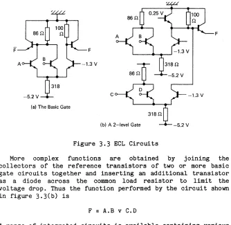
Clearly, performance was to be measured in terms of system throughput rather than raw machine speed. Significant factors were to be sought from optimising the hardware to meet the software requirements and an available production technology was to be used. Indeed the chosen technology was that to be used in the construction of ICT 1906As. However, it was anticipated that associative storage would play a significant role in the system design [3] and that suitable integrated circuit elements would be developed for this purpose.
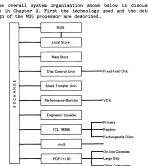
On the hardware side this book is mainly concerned with the design and implementation of the MU5 processor. However, the design was intended for a range of machines and the actual processor built is one example, which is towards the top of the range, with a scientific bias. The range was intended to go from machines of about PDP-11 cost to a mUlti-computer system incorporating several MU5s with differing biases at the top of the range. Thus the MU5 built has an 'Exchange' to which reference is made in several places. This is the hardware unit which connects the various computers of the total system. The software description takes into account both the range and the mUlti-computer aspects.
be fortuitous that the design of the ICL 2900 is so similar to MU5 that in 1969 the possibility of MU5 being marketed as an early member of the 2900 range was seriously considered. After a three-month 'convergence' exercise in early 1970, when the designs were drawn even closer together, the idea was abandoned because of ICL' s fear that the cost of maintaining compatibility would outweigh any advantage of early availability. During this period some changes were made to the detailed design of MU5 in the name of compromise, not all of which have been beneficial. Although there has been no attempt to maintain compatibility since that time the MU5 operating system and compilers can be transferred to 2900 with ease. The converse is not true.
Software plans for the project were geared as much to the
MU5~multi-computer system and the range concept as to the MU5 processor.
'The initial operating system will be for a single computer system but it will be extended to accommodate additional computers whose structures and order codes are different from those of the 1905E. It will be modular and easily changed in order to accommodate future hardware and software developments. The detailed design of the operating system has not been completed. However, it will have the following features
(1) Some form of file storage and on-line access
(2) Job queueing and scheduling for base load jobs
(3) Priority routes through the system for urgent jobs
(4) The basic supervisor will be kept to a minimum and most of the operating system facilities will run as non-privileged programs.'
Compilers were to be produced using ideas developed from the Atlas Compiler Compiler. The emphasis was to be on efficiency, compactness and machine independence.
2
The Architecture of the
MUS Processor
The design of the MU5 processor was approached through its order code, this being the natural interface between software requirements and hardware organisation. Full interplay between the two aspects was considered vital throughout the design. Efficient processing of high-level language programs was the prime target. In 'number crunching' applications, this meant a fast execution rate for the high-level language programs. However, the system envisaged would be interactive, and to combat the system overheads this entails, it was considered important to produce small compilers and compiled programs. Thus, an order code was sought which satisfied the following conditions
(1) Generation of efficient code by compilers must be easy
(2) Programs must be compact
(3) The instruction set must allow a pipeline organi·sation of the CPU leading to a fast execution rate·
(4) Information on the nature of operands (scalar or array element, for example) should be available to allow optimal buffering of operands.
In this chapter the order code of MU5 is examined from the point of view of its use and implementation. However, a large 'part of the order code of such a highly structured system is concerned with address generation, and before discussing this it is appropriate to establish the policy relating to address validation, the mechanism which protects one user from another.
2.1 INTERPRETATION OF ADDRESSES
to indicate ownership, was not considered flexible enough for a multi-access system in which the core allocation would be constantly changing. In effect, the real address based systems considered require that all address words contain an origin and a limit, and hence relate to bounded contiguous sections of store. Also the CPU must know which words in the store are address words. It then checks that each operand address is calculated from an address word, and that it falls within the specified limits. Since all address words are known to the system, out-of-use information can be moved out of main store until next required, provided the address words involved are appropriately marked and updated. A classic example of this type of machine is the Basic Language Machine [4], although it has never progressed beyond the prototype stage. Also the Burroughs machines since the 5000 series have had a similar
type of controlled address formation, and currently the
'capability machines' promote a similar idea. Alternatively, if the order code generates virtual addresses, then special hardware is needed between the CPU and the store to validate the address and translate it into a real address. Sometimes the address will relate to information not in the main store, and the hardware will detect this and initiate its transfer, usually with software assistance. This special hardware may be a single datum and limit as for example in ICL's 1900, or multiple datum and limit as for example in the PDP-11, or a paging system as in Atlas.
The real address based systems have several attractions. Perhaps foremost from the performance point of view is the fact that the address generated by the CPU can be presented directly to the store, thus avoiding the time delay inherent in paging systems. Also the units of information delimited by address words, which would be the units the system might automatically move from one level of store to another, would
be complete logical entities (procedures or arrays, for
example). It can be argued that this is more efficient than moving fixed-size pages which represent arbitrary fragments of a program and its workspace [5]. The other side of this argument is that the problems of allocating and retrieving store in variable sized areas lead to some store not being utilised, for example because the empty areas may be too small. This has to be offset against the paging problem in which, even when all pages are in use, some will be partially occupied by unwanted information. It is by no means clear where the balance lies.
Two additional considerations led to the choice of virtual
addressing for MU5. First it was felt that the most
movement of information between levels of store. Such movement requires that the real addresses of the information moved be changed. If these real addresses are allowed to scatter through each program's private store, this task becomes complex. For example, the address words that require changing because of movement of information between levels of store are themselves subject to moving. Also, the same address might appear in several places. It was felt to be a cleaner solution to hold all information relating to the way a program maps into real store in a separate data structure outside the program and entirely under operating system control.
The second consideration was that a program should not be constrained in the way it might build a data structure within its own workspace by the mechanism for address validation. Close examination of, for example, the system proposed by Iliffe [4] will reveal the awkward constraint that arrays must be homogeneous.
Once the decision to base the system on virtual addressing had been taken, it was not difficult to reject the single da tum and limit approach. Al though such a sys tem lead s to an extremely simple organisation within the operating system, the entire program must be placed in a contiguous area of store each time the CPU is assigned to it. In contrast, one of the main attractions of Atlas had been the large virtual address space available to every user job, which could be used
sparsely without significant penalty. For example, the
compilers and operating system used the top half of the virtual store, user code was compiled into t~e bottom quarter, and the next quarter was used for the stack work space. Other smaller entities such as input and output buffers were fitted into the gaps in between. From this informal partitioning of the store on Atlas grew the idea of formalising the division into a segmented virtual store, which is also exploited in the Multics system [6].
In MU5 the final decision was to use a large virtual address, and to subdivide it into a segment number and a displacement within the segment. It was anticipated that large systems would be paged, but . that small ones might employ multiple datum and limit registers (one per segment).
2.2 THE ORDER CODE
2.2.1 Choice of Instruction Format
instruction contains only register addresses, so that main store is addressed indirectly through registers, several addresses can be accommodated. If full store addresses are to be used, then one is usually the limit, although some
machines, for example the PDP-11 , have variable sized
instructions and allow up to two full store addresses to occur in the long instructions.
It was decided from the start of the MU5 design that in o.rder to comply with condition (1) above, there would be an address form corresponding to each form of operand permitted by high-level languages. Furthermore it was felt that to have more than one such operand per instruction would conflict with conditions (2) and (3). Only one facet of high-level language programs caused concern on account of this decision. This was the known high rate of usage of simple instructions such as
I := I + 1
Clearly, three instructions would be required to implement this in a one address code. However, the high execution rate expected of these simple orders and the possibility of them overlapping with adjacent orders was thought to compensate. For other reasons the possibility of using addressable fast registers for frequently used operands or addresses was rejected in favour of hardware optimisation using associative memory. First there was the desire to simplify the software by
eliminating the need for optimising compilers. Equally
important though was the desire to have fast procedure entry
and exit, unfettered by the need to dump and restore
registers. Thus through general design considerations the choice of format was restricted to the zero address (stacking machine) type or some form of one address code.
From a compiler point of view the stacking machine is attractive. The simple algorithm for translating from Algol to Reverse Polish (and hence to stacking machine code) which forms the basis of the 'Burroughs Compilogram' is a convincing demonstration of this. Its simplicity stems from the fact that operands carry directly over to Reverse Polish without any relati ve change of position and a simple push down stack is all that is required to sort the operators into correct sequence. Consider for example
(A + B) • «C + D) / (E + F»
which in Reverse Polish becomes
There were two arguments which steered the MU5 design away from the stacking machine form. The first is related to efficiency of hand-coding, which is something of a paradox
since MU5 is a high-level language machine. However,
observations on Atlas indicated that while high-level language programs were running, the CPU typically spent half its time executing in a small set of library procedures concerned with
1/0 handling, mathematical functions, etc. This basic library
would be hand-coded. Thus from the performance point of view, this small amount of hand-coded software was just as important as all the compiler generated code. Unfortunately most of the hand-coded sequences worked out worse in stacking machine code than in single address code. This was because the main
calculation, the address calculations and the control
counting, tended to interfere with each other on the stack. The problems are illustrated by the following example of a simple move sequence, although either machine could have a single function for this purpose.
Single Address Code Stacking Machine Code
LOAD MODIFIER
X: ACC
=
SOURCE[MODIFIER] ACC=>
DEST[MODIFIER]STACK MODIFIER X: DUPLICATE DUPLICATE
INC AND TEST MODIFIER STACK SOURCE[TOP OF STACK]
swap
IF NOT END BRANCH XSTORE DEST[TOP OF STACK] STACK 1
SUBTRACT
IF NOT END BRANCH X
The point being made is that a single stack is under pressure when it has to support all the (unctions involved in counting, address calculation and main calculation. In any
given context, detailed changes to the specification of ~.
instructions would ease the problem, but only at the expense of it recurring in a different context. A machine with several stacks would have worked better, for example
a control stack an index stack an address stack the main stack
This sort of arrangement would also fit the pipeline
requirement better since the stacks could be distributed along the pipeline.
example
A := B + C
For the two types of instruction format under consideration it would be coded as follows
ACC = B ACC + C ACC => A
STACK B STACK C ADD STORE A
If the operands normally come from main store the execution times of each of the above sequences would be about the same, since they will be controlled by the access times for A, Band C. However, if an operand buffering scheme is utilised, giving a high hit-rate (say> 90%) for operands such as A, Band C, the access time to the stack becomes important. On MU5 the stack and the operand buffers would be the same speed, and the above example would have caused six stack accesses in addition to the three operand accesses. Some, but not all, of the
acc~sses could have been overlapped.
o#A
The instruction format eventually chosen for MU5
represented a merger of single address and stacking machine concepts. All the arithmetic and logical functions take one operand from an accumulator and the other operand is specified in the instruction address. Thus a sequence such as
ACC = B ACC + C ACC => A
typifies the style of simple calculations. However, there is a stack, and a variant of the load order (*=) causes the accumulator to be stacked before being re-Ioaded. Also a special address form exists (STACK) which unstacks the last stacked quantity. Thus, the above example could be written in MU5 code in a form approximating to Reverse Polish, as follows
ACC = B ACC *= C ACC + STACK ACC => A
A more realistic use of the stack is in conjunction with parenthesised subexpressions. For example, the expression
would compile into
ACC
=
A ACC + B ACC*=
CACe + D
ACC
*=
E ACC + F ACC I: STACK ACC*
STACKIt is interesting to observe that if the operand to the left
of an operator is stacked, it _ subsequently appears as the
right hand side of a machine function. Therefore, for the non-commutative operations '-' and
'I',
the reverse operations denoted '-:' and '/:' have to be provided. In the notation used throughout this bookACC I OPERAND means
ACC I: OPERAND means
etc.
ACC
=
ACC / OPERAND ACC=
OPERAND I ACCOnly one stack is provided in MU5, but there are five
'accumulators' or 'computational registers'. Each may stack its contents, and hence the effect is the same as having five stacks, provided the order of unstacking corresponds to the way the stacked quantities are interleaved. This condition is usually met. If it were not, the conventional stacking machine would not be acceptable. The significant difference in MU5 is
that the top words of each of the five stacks are
simultaneously available in the computation~l registers. Each
of the registers serves a dedicated function and they are distributed along the pipeline in close proximity to the
arithmetic unit associated with that function. These
arithmetic units are
The B-unit - used for index arithmetic and control qounting
The D-unit - used for address modification and bound checking
The A-unit - the main arithmetic unit providing fixed-point,
floating-point and decimal facilities
The registers are
B
DR XDR
X
A(ACC)
- a 32-bit modifier register
The existence of two registers X and A in the main arithmetic unit is largely historical, although there is some advantage in being able to perform control calculations in X
without disturbing a partial result in A. Originally the
system had two registers in the B-unit. These were notionally thought of as a modifier (BM) and an integer accumulator (BA) to be used for control calculations. However, the order code was symmetrical allowing both to be used as modifiers, and this could be usefully exploited in some of the hand-coded library procedures. During the 'convergence' exercise with ICL, the BA register was forfeited and replaced by the X register in the A-unit. However, the success of the pipeline approach described later is dependent upon the control and address calculations proceeding independently of the queue of orders waiting for the A-unit. Thus as well as being used as a modifier, B may also be used for simple integer calculations such as
I := I - J + 2
The X register is only used when the operands of the
calcula tion require B to be used as a modifier, or when the operation is not provided by the B-unit (divide, for example).
The instruction format provided for operating on these registers is
CR 3
F
4
ADDRESS
9
One combination of the CR (computation register) bits
distinguishes a second format for the 'Organisational
Instructions' concerned wi th control branching and
manipulation of 'addressing' registers. The remal.nl.ng seven combinations qualify the function (F) as follows
1 fixed-point operations on B 2 fixed-point operations on X
3 floating-point operations on A
4 decimal operation on A
5 unsigned fixed-point operations on A (used for -multi-length working)
6
manipulation of DR and XDR7 string processing functions (mainly for Cobol)
Even with these seven groups of functions, the existence of only four function (F) bits is restrictive, but the operators
necessary for high-level language translation can be
accommodated. It is the orders more commonly associated with
hand-coding, such as shift operators, that have to be
such orders are used mainly for the selection of packed operands which in MU5 is carried out automatically by the D-unit. Groups 6 and 7 are discussed later.
There is close similarity in the functions provided in groups 1-5, the following being typical
=
load (32-bit operand)='
load (64-bit operand)*=
stack and load=>
store+ add
subtract
*
multiply/ divide
-=
logical non-equivalence (exclusive or)V logical or (inclusive or)
<-
shift & logical and-: reverse subtract
COMP compare
CINC compare and increment
/: reverse divide
In the case of organisational instructions it was felt that more functions were needed, so the address field was shortened to give the format
CR
=
03
F'
6
ADDRESS
7
These F' functions are summarised in Appendix 1. It can be seen that they fall into four main groups, namely
Control transfers including procedure entry and exit addressing register manipulation
conditional control transfers boolean
Some of the procedure entry functions (XCO, XC1, ••. , XC6) provide entry to seven groups of Operating System procedures. Their action is to stack the operand, which defines the Operating System procedure required; then after setting the executive mode bit (section 2.3.1) they force control to fixed addresses in the Operating System. This controlled entry to Operating System is vital in maintaining the security of the system. ,Another form of entry to the Operating System occurs as a result of an 'interrupt' (section 2.3.1).
self-explanatory. They are used mainly at procedure entry and exit time to achieve the effeats described in section 2.2.2.
Conditional control transfers usually only branch a short distance. Therefore to help keep instruction sizes down their operands are interpreted as relative addresses to be added into the Control Register. As a further minor convenience to the software writers, provision is made for the complementary form of each standard condition to be specified (both
,>,
and'~' are provided, for example). The shortage of functions
precludes the possibility of the tests applying to the registers. Instead, they apply to condition bits which are set
by the compare (COMP) and compare and increment (CINC)
functions.
There are two kinds of boolean function included in the
order code to facilitate the implementation of boolean
statements in Algol-like languages. Both allow the standard logical operations to be applied to the Boolean Register BN and a boolean operand. In one set the least significant bit of the instruction operand is taken as the boolean operand, while in the other the operand part of the instruction is used to
extend the function, and it defines the operation. The
function itself specifies a conditional test to be applied to the condition bits. The result of this test is taken as the boolean operand.
The use of these boolean functions is demonstrated by the translation of the Algol conditional statement
IF (a
=
b OR x>
y) AND t THEN 'ST1' ELSE 'ST2';where a and b are type INTEGER, x and yare type REAL and t is type BOOLEAN. With only straightforward local optimisation it is
B
=
aB COMP b BN = IF= ACC
=
x ACC COMP Y BN V IF>
BN & t BN-=
1 IF BN,->
L1'ST1'
->
L2 L 1:Unfortunately it was realised too late that the function 'IF-BN' should have been provided, hence BN sometimes has to be inverted before the test as in the above example. It could be eliminated if the compilers were clever enough to compile code to compute the 'not' of the condition.
Until the mechanics of address generation have been
described, the example below may not be completely understood.
It is given at this point to emphasise the close
correspondence between the high-level language form of
arithmetic assignments and the machine code. Each line except the JUMP order would be a 16-bit instruction if the example was taken from an average Algol program.
W := Z[I - 1]
*
F + C(P,Q) / Y[J*
3
+ K];becomes
B = I B - 1 ACC = Z[B] ACC
*
F STACK ACC STACK LINK L1 STACK P STACK QJUMP C
L1: B = J
B
*
3
B + K ACC / Y[B] ACC + STACK ACC => WThe total size is 32 bytes and this includes automatic bound checks on Z and Y. The reader is invited to compare this with the size of the corresponding sequence on other machines.
2.2.2 Address Generation
An examination of the operands in high-level languages indicates that provision should be made for
SCALARS
ELEMENTS FROM ARRAYS OR OTHER STRUCTURE~
STRINGS LITERALS
FUNCTIONS (PROCEDURE CALLS)
Also the procedure organisation of languages allows operands to be
LOCAL (to the current procedure) NON-LOCAL (or COMMON)
GLOBAL STACKED
Clearly the scalar variables have names and provision is made in the order code to accommodate these names together with an indication of whether they are local or non-local, etc. This identification of names becomes very important when considering the hardware design of the processor. Studies of programs run on Atlas indicated that over a large range of programs, 80% of all operand accesses were to the named operands, and that only a small number of these named operands was in frequent use at anyone time. Thus a system which kept these operands in fast registers would be able to achieve high performance, but for the reasons already discussed, the use of addressable fast registers was rejected. The alternative solution adopted in MU5 involves the use of an associatively addressed 'Name Store' which forms part of a 'one-level store' with the main store of the processor, and in which the allocation of named operands to registers is performed solely by the hardware.
instruction. Also, to provide the generality required for the Algol-like languages, a mechanism for procedure calling is integrated into the stack concept.
Before considering the address generation in detail it is necessary to describe the intended store layout and the function of the dedicated addressing registers. These are
NB a pointer to the scalars and descriptors of the current procedure
XNB a pointer used to access any non-local or common scalars and descriptors
SF a pointer to the stack
o
this is a pseudo-register always giving zerofor access to global scalars and descriptors
The overall storage organisation provides each program with a segmented virtual store. One segment (or more in the case of languages which allow parallelism) is used for the named operands and the stack (the scalars and descriptors), while
the rest are used for code and the secondary operands
(elements of arrays and other structures). The segment holding the named operands is called the Name Segment or Procedure Stack. Its layout is given below.
! DISPLAY ! GLOBALS ! 1st PROe ! CURRENT PROC
T
T
NB SF
There is a 'level of stack' in the Name Segment associated with each activated procedure, which is released when the procedure ends. Each level starts with a 'Link' to be used to exit from the procedure. The parameters and the local named variables of the procedure follow. Thus on entry to a new procedure, the Link (containing the return control address and NB) is stacked, next the parameters are stacked, and finally the procedure is entered. Inside the procedure NB is set to the address of the Link, and SF is advanced over the space required by the local names. SF may be further incremented, as
operands .are stacked, by means of the *= function and
decremented, as they are unstacked, by means of the special operand STACK. In the case of languages which allow non-local access to the names of other procedures, an entry is also made in the Display.
XNB from the Display and then accessing relative to XNB. In recursive situations it is necessary to stack the old Display value on procedure entry, so that it may be re-set on exit. This mechanism is obviously geared to the dynamic storage allocation of Algol-like languages. If the allocation scheme is static, as in Fortran, the Display does not exist and XNB is used to address 'common' variables. The global variables at the beginning of the stack segment are conceptually 'own' yariables. They are perm"anently allocated, and hence can remember information between different calls of a procedure. Exit from a procedure requires that the Display be re-set if it was stacked on entry, then SF is re-set to NB, and NB and control are re-set by unstacking the Link.
Thus the standard procedure call is a minimum of two instructions
STACK LINK JUMP
L 1 :
L1
procedure name
If the procedure has parameters, additional instructions are needed between these two to stack each parameter. Inside a procedure which has no nested procedures making non-local access to its names there will be three more instructions concerned with the 'red tape' of procedure calling.
NB
=
SF - space accepted by LINK and PARAMETERS SF=
SF + space required for local namesEXIT
The more general case involves manipulation of the Display as already described.
For reasons which will become clear after the buffering strategies are described, the Name Segment is not used for arrays. Therefore the software must run its own 'secondary stack' for dynamically declared arrays.
2.2.3 Address Encoding
The machine is designed to recognise that high-level language operands are referenced by name (or are constants). Hence the
instruction addresses corr-espond to names (or literal
constants).
In the 16-bit instruction format the encoding chosen is
CR(3) F(4) N(6)
or in the case of organisational functions
CR=O F' (6) k' (1) N(6 )
The N field corresponds to the operand name; thus the first declared name has N
=
0 the second N=
1, etc. Of the eight combinationsname, one is the rest are
k = 0 k = 1 k = 2
k = 3
k = 4
k = 5 k = 6
of k, which notionally specifies the kind of reserved to distinguish an extended address, and
use N as a 6-bit signed literal
use N as a register name (B, DR, etc.) use N as the name of a 32-bit local scalar
i.e. operand is 32-bit store line (NB+N) use N as the name of a 64-bit local scalar
i.e. operand is 64-bit store line (NB+2N) use N as above but pass operand to the D-unit
for a modified secondary access (name[B]) spare
as k
=
4 but secondary access is unmodified i.e. name[O]Obviously only two of the above forms can be associated with k' and these are
k' = 0
k.' = 1
use N as a signed literal extended address
There are three other requirements not met by the above which have to be provided by the extended address of longer instructions. First, there are the names relative to the other addressing registers, XNB, 0, SF (the non-locals, the globals and the stacked operands, respectively). Second, there are the local variables in procedures where more names are declared than can be encoded in the 6- bi tN. Third, there are the literals bigger than six bits. Thus both the k field and the N field have to be extended, and the general form of extended instruction has the 32-bit format
CR(3) N'(16)
F(4) K(6)
From the detailed encoding of K (giv:en in Appendix 1) it can be seen that in some cases the N' is omitted and the instruction again reduces to 16 bits. Also, in the case of Ii terals, more 16-bi t pieces may be added up to a maximum instruction size of 80 bits.
2.2.4 Secondary Operands
In order to access data structure elements, descriptors are passed to the D-uni t, together with an indication of whether or not modification is required. The unmodified descriptor is
retained in the DR register and can be used again. If
modification is specified the modifier is taken from B.
Two main types of descriptor are provided. They are
String Descriptors
Vector Descriptors
Ts 8
Tv 8
LENGTH 24
BOUND 24
ORIGIN 32
ORIGIN 32
String descriptors describe strings of bytes. If the string is short enough it can be accessed as a normal operand. Short strings are always right justified and filled out to the register size with zeros. A more usual use of the string descriptor is in conjunction with the string processing functions.
In the vector descriptors the type bits (Tv) control the modification, and give the size of element in the array. This may be 1, 2, 4, 8, 16, 32, 64 or 128 bits, but the present MU5 hardware does not implement the sizes 2 and 128. As with strings, short operands are right justified and zero filled. Normally the modifier is checked against the bound (and that it is 2. 0), and an interrupt is caused if the check fails.
Before addition of the modifier and or1g1n occurs, the
modifier is scaled. This means that the displacement caused by modification is in units of element size. Special bits within the type allow both the bound check and the scaling to be inhibited.
standard programming languages, the idea few occasions where the operand type is
time, a software escape is provided
descriptor type which forces a procedure used. The main use of this mechanism implementation of Algol 'thunks'.
was dropped. For the not known at compile
through a special
call whenever it is though, is in the
It has been a constant source of regret that only one bound could be fi t ted in to the final descriptor format. Until the 'convergence' exercise the design was based on the following descriptor format containing two bounds
LOWER BOUND 16
UPPER BOUND 16
TYPE/ORIGIN
32
This had the additional advantage that programs which forfeited the bound checking could use 32-bit descriptors. The main argument in favour of the alternative format was based on the need for·a very large virtual address. In the original MU5 descriptor the address size changed with element size, being 24 bits for 32-bit elements, 25 bits for 16-bit elements and so on. Experience with the MU5 system to date indicates that the above address, giving 256 segments each of 1/4 Mbyte size, would have been more than adequate. Of course the 16-bit bounds were marginally restrictive and the hardware bound check had to be forfeited in some very large programs. To compensate for the loss of double bound checking, facilities are provided for the XDR register to point to a 'dope vector' while the address of an element in a multi-dimensional array is buil t up in DR. This dope vector contains triples, which are the two bounds and the multiplier (or stride), for each dimension. Each subscript is computed.. in B and a special function is then used which checks against both bounds and computes the displacement before adding it into DR.
Aqother deficiency of the present format is that string descriptors apply only to byte strings. In an earlier design strings could be of any size of element from single bits up to words. This, combined with the ability to manipulate complete strings (provided they were not too big) in the registers, was a powerful means of handling the 'structures' of more modern languages such as Algol 68. Perhaps too much emphasis was placed on Cobol and Fortran, and the growing importance of the Algol 68 type of data structures in, for example, system programming languages not fully appreciated. Even so, the descriptor system, which is common to both MU5 and ICL 2900, offers more facilities in support of Algol 68 than most machines.
2.2.5 Array Operations
The instructions and operand forms available for vector
operations in a conventional language are now examined in more detail. Data structures, and fields wi thin such structures, are described using vector descriptors of the form
Tv BOUND ORIGIN
The type bits (Tv) include the size of each element of the vector, which may be between 1 and 64 bits. The Bound Field contains the number of elements in the vector, while the Origin Field comprises the address of the start of the vector. The instructions required to access element i of a vector z are
B
=
iACC
=
z[B]Load the B (modifier) register with the subscript i accumulator = the Bth element of z
Th.e instruction ACC = z[B] first loads the descriptor z into the DR register. Then B is scaled according to element size, added to the origin of DR and the required element is
accessed. Simultaneously, a check is made that B is in the
range 0 ~ B
<
Bound, and an interrupt occurs if this check fails. This coding, and that in subsequent examples, assumes that the lower bound of the array is zero. If this is not the case, an additional instruction is needed to subtract the lower bound from B. On conventional machines, even omitting the bound check, several orders are used to access a dynamic array element. This is the principal reason why many compilers attempt to optimise subscript calculations.A simple example of the use of vector accessing orders is the scalar product loop
which becomes
FOR i .- 1 STEP 1 UNTIL n DO sum := sum + x[i]
*
y[i];B
=
1 LOOP: B => iACC
=
x[B]ACC
*
y[B]ACC + sum
ACC => sum
B CINC n
IF /=, ->LOOP
This assumes that the compiler optimises out three unnecessary B : i orders but that it does not optimise to the extent of moving the B
:>
order to outside the loop. Hence the loop comprises seven 16-bit instructions. The performance of this loop is discussed in Chapter 11.The group 6 functions mentioned above are concerned with manipulating descriptors and the registers of the D-unit. Some of these functions, namely DR:, SUB1, SUB2 appear in the examples below. A full list is contained in Appendix 1.
A descriptor z may describe a vector of descriptors so that the sequence
B : i
DR : z[B]
B : j ACC : DR[B]
could be used to access an element z[i,j] of a two dimensional array. Use of a multiplication technique with the subscript arithmetic taking place in B has the advantage that the subscript calculation is independent of operations queued for
the main accumulator. It does, however, require a fast
multiply function in the B-unit. In this case z[i,j] becomes
B : i B
*
n B + jACC : z[B]
In this case only the final access, not individual subscripts, is bound checked.
A further, more elaborate, hardware facility is provided to deal with the full generality of array accessing in Algol. This is convenient for arrays with dynamic upper and lower bounds, or cross-sections of arrays. It uses a dope vector containing three 32-bit elements for each dimension, namely, a lower bound which is subtracted from the subscript, an upper bound against which the subscript value is checked, and a stride by which the subscript is multiplied. The hardware instructions SUB 1 and SUB2 use this dope vector for such subscript calculations. Thus z[ i, j] with full bound checking becomes
B : i
SUB1 z1
B : j SUB2
process first subscript using dope vector z1
B
=
DO ACC=
z[B]move composite subscript to B access element
The SUB 1 order causes the XDR register to be loaded with the descriptor of the dope vector and, after bound checking B, it sets the origin of the DR register (DO) to the product of (B - lower bound) and the stride of the first triple. Each subsequent application of the SUB2 order steps DO on to the next triple, and after bound checking the value in B, it adds the product (B - lower bound)
*
(stride) into DO.2.2.6 String and Vector Operations
Special purpose orders are provided for the string processing functions which occur in Cobol and PL/1. These fall into two
classes string-to-string and byte-to-string. The
string-to-string orders operate on two fields, or strings,
each described by a descriptor. The descriptor of the
destination string is held in the DR register while that for the source string is held in a second descriptor register,
XDR. As the operation of the instruction proceeds, the
descriptors in DR and XDR move along the strings. No visible register is used by the strings themselves. The operand of the order is an 8-bit mask, that determines which bits within each byte are to be operated on, together with an 8-bit filler and in some cases four 'function' digits used as described below. Provision is made in the hardware for these orders to be interrupted (section 7.4.3). Examples of the orders are
SMVB Move one byte from the source to the destination
string, or use the filler byte if the source is exhausted.
SMVF Move the whole source string to the destination
string followed by filler bytes if the source is shorter than the destination.
SCMP Compare the source and destination strings byte by
byte ending when inequality is found, or the
destination string is exhausted.
SLGC Logically combine the source and destination strings
into the destination. The form of combination
(logical OR, for example) is selected' by the
'function' bits in the operand.
Consider the use of .these orders in the implementation of the MOVE verb in Cobol. Suppose that two fields C and Dare specified
02 02
C D
PIC PIC
In MU5 descriptors would be created at compile time for C and D, each describing a 7 -byte field starting at the required byte address. The Cobol sentence
MOVE C TO D
would then become in MU5 instructions
XDR
=
C DR=
DSMVF
If D is specified as
02
set source descriptor for C set destination descriptor for D
move the field described by XDR to that described by DR
D PIC X(9)
then the final two bytes of D must be spaces. The filler option of SMVF allows this to be carried out automatically. The sequence becomes
XDR
=
C DR=
D SMVF 'space'If the source field is too long, then the SMVF order
terminates when the destination field is full, and an optional interrupt enables this condition to be monitored if required.
Extension of the above technique to vector operations of a mathematical form was considered. For example a vector add of the form
would become
F:= F + E
DR
=
F XDR=
E VECTOR ADD2.3 ORGANISATION OF THE HARDWARE
The design of the hardware of the MU5 Processor initially centred around the Name Store and the descriptor mechanism. Simulation studies of the Name Store indicated that a hit-rate of around 99% could be obtained with 32 words of store. The special associative circuits designed for this store were expected to be capable of operation in 70 (later to become 40) ns, but an additional 70 ns was necessary to read the value from the conventional field. However, a fixed-point arithmetic unit could be constructed to perform simple functions such as addi tion and subtraction in under 50 ns, using the MECL 2.5 technology from which MU5 was to be built, and clearly the two activities in the Name Store would have to be overlapped if the store speed was
I
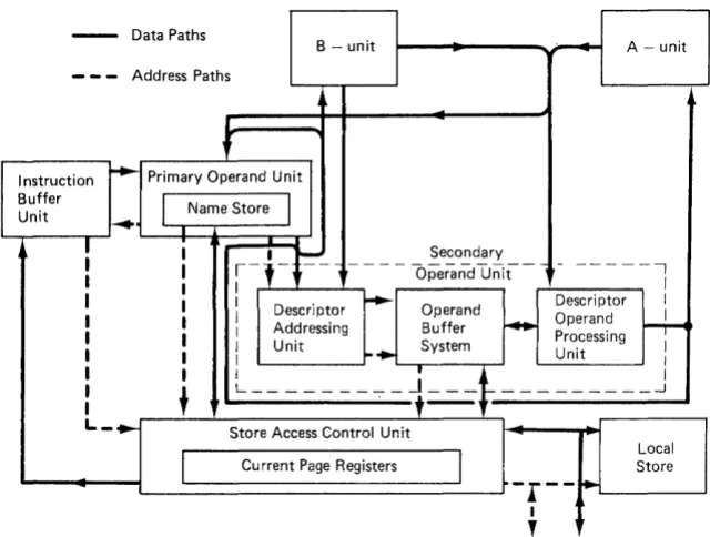
to approach the arithmetic speed. Furthermore, the additibn, of name to base register, required a comparable amount of time, and so the design was based on an instruction pipeline (with 5 stages) eventually called thePrimary Operand Unit (or PROP). PROP would receive
instructions at its input and supply at its output functions
and primary operands ready for execution or further
interpretation by the descriptor system.
- -
Data Paths.--.
B - unit A - unit
---
Address PathsI
I nstructi on
....
Primary Operand Unit BufferI
Name Store Unit~
I
I I
r-l-f-
SecondaryI I - - - : -
---,
I I Operand Unit I
I I Descriptor
....
Operand Descriptor II I Operand I
I I Addressing Buffer
...
Processing ~ Unit System II I
-.
Unit II I
' - t
I
I
t
---~-~--- ---~I
,
~L_ ... Store Access Control Unit
Local
I
Current Page RegistersI
StoreI--r--
~I
,
To/From Exchange
Figure 2.1 The MU5 Processor
A number of consequences flowed from the adoption of this configuration, ·particularly in relation to the positioning of the Control Point (the position an instruction must reach
before the Control Register, or Program Counter, is
incremented). On the one hand the Control Point should be as far along the pipeline as possible so that any interrupts caused by an instruction can occur before the Control Register is altered, while on the other hand it should be as early in the pipeline as possible, since fewer instructions must then be discarded (and hence replaced) if the wrong sequence of
instructions is proceeding behind a control transfer
instruction. The need to preserve the state of the Processor at an interrupt is also important, so the fact that instructions alter registers at different points along the pipeline has to be considered carefully. In MU5 it was decided that the Control Point should be placed at the end of PROP, which itself executes all the organisational orders, and from which point orders proceeding to the B-unit can be guaranteed to complete. Furthermore, each instruction reaching the end of PROP will have obtained its primary operand or given a page fault interrupt due to its unavailability. Having made the Control Point decision, there remained two problems
( 1) how to supply instructions to PROP at a high enough rate, especially after control transfers,
(2) how to deal with page faults arising from secondary accesses.
The problem of fetching instructions in normal sequence appeared comparatively straightforward. The design speed of PROP increased, as experience was gained with the associative circui ts, to a nominal maximum rate of one operation, or 'beat', in 40 ns. Each beat could require 16 instruction bits from the IBU, giving a maximum data rate of 400M Bps. The main store, a 250 ns cycle-time plated-wire system, was to be constructed of 128-bi t wide stacks, and would therefore be able to supply, without interleaving, 500M Bps. Interleaving would improve this rate, so that even allowing for operand accesses (and the Name Store would intercept most of these), there would be no problem in supplying instructions at the required rate. Problems would arise for control transfers, however. These were expected to occur on average once every ten orders, and would create long gaps in the instruction stream because, despite the high data rate, the store access time was comparatively long. A number of alternative solutions were considered, and simulation studies were made of the different possibilities. The solution chosen is based on a 'Jump Trace' mechanism (section 4.1), which attempts to
predict the result of an impending control transfer
instruction. Consideration of measurements taken from Atlas, and simulation studies of this system, showed that it was possible to predict correctly the sequence of instructions following control transfers in about 65% of cases, and that only eight lines of Jump Trace store would be necessary to obtain this efficiency.
A function leaves the Queue when the word containing its operand is received from store. Since the store accessing system is itself a form of pipeline, the effective access time
is reduced by a factor corresponding to the number of
posi tions in the Queue. In a synchronous system, no extra operand buffering would be required, but because the MU5 Processor operates asynchronously, it is essential that as many buffers as Queue positions be available to receive the returning store words. Thus an Operand Buffering System (OBS) became an essential part of the Processor design. This system, together with the D-uni t, forms the Secondary Operand Unit (SEOP). Simulation studies of this system showed that by fetching 128-bit store words containing the required operand, and retaining these words in associatively addressed buffers, many operands are thereby automatically pre-fetched, and the corresponding store requests avoided.
A significant fraction of the access time for secondary operands is taken up with generating a virtual address and obtaining either a real address or a page fault interrupt. In the case where such an interrupt arises, however, the Control Register will have been incremented on beyond the address of the corresponding instruction. Therefore in order to be able to re-execute the instruction after the interrupt has been serviced, the Queue is designed to contain all functions for which store requests are outstanding. The Page Registers can then be manipulated by the Operating System using orders which do not involve the Queue, or, if a process change is required, the whole of the Queue and its associated buffer registers can
be preserved (for subsequent restoration) in the store,
thereby unblocking the Queue and allowing other processes to be run.
The inclusion of a Queue in the design generates additional problems because of the different types of operand to be sent to the A-unit. ACC orders using named variables are ready for execution at the end of PROP, but since orders must be obeyed
in correct program sequence, they cannot be allowed to
overtake ACC orders awaiting secondary operands. Various
the A-unit, the logical place for which is within the Operand Buffer System. Thus OBS actually contains 8 lines x 128 bits of Vector Store, 24 lines x 64 bits of Name Store together with 8 lines x 64 bits for literals supplied by PROP. The hardware automatically ensures that names used with ACC
functions are normally kept in OBS, and names used with
non-ACC functions in PROP, and also deals with any necessary interactions.
2.3.1 Interrupts
In the previous section we were mainly concerned with the normal execution of instructions, but the design .must also
provide for exception cQnditions which give rise to
interrupts. Already mentioned is the page fault, or
non-equi valence, interrupt which is discussed more fully in section 9.3. There are other interrupts, and they can· be broadly classified into
program based interrupts
external event based interrupts system error interrupts
Examples of the first kind are
the CPR non-equivalence interrupt illegal store access interrupts
descriptor faults (e.g. bound check fail) arithmetic overflow
of the second kind
transfer complete interrupts timer interrupt
and of the third kind
parity error
power failure warning
orders in the pipeline can be inhibited by program. In fact, by using a register-register order which stores the content of the ACC into an imaginary 'Z' register in the B-uni t, no further orders can leave PROP until the A-unit has completed all outstanding orders (section 4.2.4). Normally this order is not used, but the compilers allow the user to choose to have it inserted in cases where the source of error is difficult to trace. One option is to have 'ACC
=>
Z' compiled after the last machine instruction in the translation of each source statement. This enables the error condition to be related to a particular source instruction. Another extreme option would be after every machine instruction.Some descriptor faults (illegal type/size combinations, for example) occur precisely in MU5, but the bound checking occurs too late in the cycle of events in the D-unit to allow a precise interrupt. The reasons for this are discussed in Chapter 5. This imprecision restricts the usefulness of the bound checking facility, and a different organisation of the hardware would be used in a redesigned machine. As it stand s the program knows of the interrupt, but cannot in general rectify the condition and continue, because a few orders
overrun might have occurred. In the case of CPR
non-equivalence, the interrupt must at least be made to appear precise, since the order causing it cannot complete until the
interrupt is serviced. Hence the special arrangements
involving the Function Queue in OBS, described above.
With the second and third groups it is enough to inject the interrupt into the pipeline and allow preceding orders to complete.
From the software point of view, interrupts are best classified according to the action they require. Thus in MU5 there are eight types of interrupt, divided into two groups of four, the System Interrupts and the Process Interrupts. These interrupts are
System Interrupts
Process Interrupts
System Error
CPR Non-equivalence
Exchange Transfer Complete Peripheral Window and Timer
Instruction Count Zero Illegal Order
Program Fault Software Interrupt
by the setting of bits in the Machine Status register, such as the ' Level 0' and ' Level l' digits. The Level 1 digit is
normally set during the running of a Process Interrupt
procedure, and, as well as allowing access to the privileged V-store operands, it inhibits any other Process Interrupts. System Interrupts can still occur, how:ever, since these are only inhibited by the setting of the Level 0 digit. The Machine Status register also contains an Executive Mode digit which allows fully interruptable but privileged code to run, digits which inhibit the types of Process Interrupt a program may wish to deal with itself, the Test bits used by control transfers, and other miscellaneous digits.
Associated with each type of interrupt are two words of protected core resident information, known as the Old Link and New Link. When an interrupt occurs, the existing instructions in the PROP pipeline are abandoned, and the contents of the Control Register, Name Base and Machine Status registers are
preserved in the Old Link. These registers are then
overwritten, by a control transfer instruction, with the information held in the New Link. Thus it is the setting of bits in the Machine Status part of a New Link that determines the interrupt inhibit status of the procedure which services an interrupt. At the end of the interrupt procedure, the information preserved in the Old Link is normally used to restore the Processor to its original state.
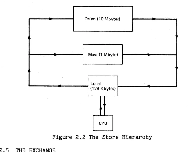
2.4 THE STORE HIERARCHY
The decisions concerning the stores for MU5 were taken in 1968. This was before large capacity high speed semiconductor stores had become feasible, and the most promising development among the analogue store technologies was plated-wire. Plessey had a plated-wire store under development with an expected cycle time of 250 ns. Unfortunately the price of £16 750 per 2K stack of 128-bit words was restrictive.
MU5 was being designed as a machine to run very large programs, and support the order of hundreds of interactive terminals. Although the terminal activities would be very variable, their store requirements were not be expected to be less than thousands of words. Thus a total store requirement of several million words was anticipated. Clearly it could not be by plated-wire store only. In fact, for this size of store, even medium speed (2.5 J.ls) core store available from Philips at £41 500 per 128K stack of 32-bit words was too expensive. A
store hierarchy with some plated-wire store to obtain
Ideally the store at the fast end of the hierarchy should be large enough to accommodate the active parts of several interacti ve jobs, and a background job. If an Atlas type of 'one-level' store with demand paging is to be used, the transfer time for pages must be matched to the machine speed. Consider an MU5 with a 10 MIPS instruction rate and a modest sized main store backed up by a drum with a 20 ms revolution time. Even with very high packing density on the drum, page transfers would cost on average 10 ms. This time would be equivalent to 100 000 instruction times. If a page size of 1K bytes was used, then for 75% CPU utilisation to be achieved, a program must obey 300 instructions for every byte of each new page brought in to store before requiring further new pages. Clearly, this intensity of CPU usage would not apply to the pages that might be considered to be the active part of a program such as those containing
(1) the frequently used facilities and working space of a compiler
(2) an array to which a simple cyclic algorithm applies
unless, of course, they could simul taneously fit into store. Therefore, the conclusion was that if the plated-wire store is not big enough to accommodate the active parts of several jobs, an intermediate store, very much faster than the drum (for demand paging) , is needed between the two.