USER'S GUIDE TO
VECTOR GRAPHIC SYSTEMS USING·MOOS
MOOS System Diskette version 8.5
USER'S GUIDE Revision B October 18, 1979
IMPORTANT: 'Ibis manual is for MOOS System Diskettes 8.5 (lilLY.
'Ibis manual AND Diskette 8.5 are for use only with systems having 56K of contiguous memory.
Please turn to the ERRATA following the title page.
To start up a system using MOOS, see first page of Chapter 2. ~
·
, ,
\ ." .
... ' ,'J
.:: '
: copyr'ight: 1979 by VeCtor Graphic Inc. All rights reserved.
Disclaimer ' ,
Vector Graphic makes no representati9ns or warranties with respect to the contents of this manual it,self',' Whether or not the' product it describes is covered by a warranty or repair agt:eement.· Further, Vector Graphic reserves the right to revise this publication and to' make changes· from, time to time' in the content hereof without obligation of Vector Graphic to notify any person of such
revision or changes, except when an agreement to the contrary exists.
Revisions
ERRATA
The following sheets describe the differences between the B.4 MDOS manual and the B.5 manual. The chaI'Xle occurs because of a very significant change to
the system and the MOOS System Disk. Because of printiI'Xl schedules, the manual text is NOT modified. Please make the appropriate changes in the text. The disk, however, is ready to use.
Most of the differences derive from inclusion in the system of a 64K RAM
board which provides the user with 56K of contiguous memory. (BK are not used.) To accomplish this, all other boards having on-board memory have been readdressed (Flashwriter, Disk Controller, and PROM/RAMboards). The Extended Systems Monitor has been changed to accomodate this, and the version of the Moni tor used with the Flashwri ter board has been enhanced in other ways as well.
The MJX)S operatiI'Xl system and utilities have also been modified as requi red by
the change, and tw:> new utili ties added.
Change the following in the manual text:
If your system is a System B, the Extended. Systems Monitor Executive will prompt the operator wi th "MON>". In other systems, the Monitor prompt is still
"*". Make this change in the text wherever you find it. It appears in many places.
Change
1-1 The system has a 64K board, not a 4BK board. The user has access to 56K of this.
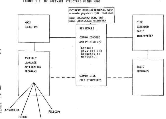
1-9 Change the chart as follows: FF40-FFFF
FC00-FF3F FB00-FBFF F000-F7FF EC00-£FFF EB00-EBFF E000-E7FF 0000-£000
Monitor stack area (on PRC>'! RAM board)
RAM available to user (on PROM RAM board) .,. Disk Bootstrap ROM and Disk Controller RAM Flashwriter video buffer
lK optional PRC>'! lK optional PRC>'!
Extended Systems Monitor 56K available to user
1-10 Top of RAM is DFFF.
Rev. B.5-6 l0/1Bn9
-, ..
1-11 Remove NOESCAPE, change FLASH7 to PLASH8, add UPDATE-RES and WORM utilities (both type EC.)
UPDAT.E':"RJ;;$
i~ u~~d
to convert MOOS System Diskettes 8.4 and before into diskettes that can run on the Update-64 systens as the 8.5 diskette can. Simply put the diskette you want to update in drive 0 (remove any wr i te protect tab), put, tite8.5 .diskette in drive 1, and type 1 : UPDATE-RES (return) while in the MIX:S Executive.WORM is a utility which tests memory more thoroughly than any other test, including MDIAG. It erases all of memory, so make sure you have saved your data on a diskette before using it. To use, type WORM (return) while in the MOOS
~ecl1t.1ve •. ~low it to repeat 5 times •. It will report any errors in memory.
2-2 N causes E000, not C000, to be displayed if the system is working properly • .
.
~. ' .. ':. ' "
2-3
, ~ .. ' . <:inc 2-13' ~ Some systems have a Bi tstreamer I board and some systems have a
Bi tstJ;:eamer II board. All configuration instructions in Chapter II apply to the Bitstreamer rI. board •. Consult the Bitstreamer II manual or Vector Graphic or its agents for instructions on interfacing with the Bitstreamer II. Basically, it has} serial ports(2&~, 4&5, 6&7) each having a data and a status port address, and 2 parallel ports (8 and 9.) Centronics drivers on the 8.5 MOOS Systems Diskette will not work with Bitstreamer II.
,~, • ; I
:- '. ~.
2-17. Ren:>ve ~ction' 2;. 3.7., (This is because the only way now to cause a return of control t9 the Extended Systems Monitor Executive is to press the RESET button on the computer chassis.)
,i'e .• 3~~' ':':Cl!~l1ge:*ctiqn 3.7 ~ explain: Depress RESET on t.'1e computer chassis to retun
control to the ftt)nitor ~xecutive. Control-Q, ESC, and control-x will not work.
3-4 Change the reference to "control-Qft to "RESET button."
Change the title of section 3.10 to "ENTERING MOOS AND M.BASIC COMMANDS." Change the contents of the section to read "All operator entries to the MOOS and M.BABIC Executives can be edited with the BACK SPACE, DEL, underscore, or control-H keystrokes. Terminate every line by depressing the RETURN key. If desired, press control-T at almost any time to reverse the video image to black on white, or back again. Some other special keys, such as the arrow keys to move the cursor, may affect the screen image, but do not use them while in the MOOS or M.BASIC Executives because these keys may confuse the Executives. (Note that other Executives, such as the Extended Systems Monitor Executive and the Word Management System do allow use of some of these special keys.) ft
4-1 Replace "ASSMft with "Z901.''
REPAIR AGREEMENT
The Vector Graphic computer sold hereunder is sold "as is", with all faults and without any warranty, either expressed or implied, including any implied warranty of fitness for intended use or merchantability. Ho~ever, the above notwithstanding, VECTOR GRAPHIC, INC., will, for a period of ninety (99) days following delivery to customer, repair or replace any Vector Graphic computer that is found to contain defects in materials or workmanship, provided:
1. Such defect in material or workmanship existed at the time the Vector Graphic computer left the VECTOR GRAPHIC, INC., factory;
2. VECTOR GRAPHIC, INC., is given notice of the precise defect claimed within ten (19) days after its discovery;
3. The Vector Graphic computer is promptly returned to VECTOR GRAPHIC, INC., at customer's expense, for examination by VECTOR GRAPHIC, INC., to confirm the alleged defect, and for
subsequent repair or replacement if found to be in order.
Repair, replacement or correction of any defects in material or workmanship which are discovered after expiration of the period set forth above will be performed by VECTOR GRAPHIC, INC., at Buyer's expense, provided the Vector Graphic computer is returned, also at Buyer's expense, to VECTOR GRAPHIC, INC., for such repair, replacement or correction. In performing any repair, replacement or correction after expiration of the period set forth above, Buyer will be ch3rged in addition to the cost of parts the then-current VECTOR GRAPHIC, INC., repair rate. At the present time the applicable rate is $35.00 for the first hour, and $18.00 per hour for every hour of work required thereafter. Prior to commencing any repair, replacement or correction of defects in material or workmanship discovered after expiration of the period for no-cost-to-Buyer repairs, VECTOR GRAPHIC, INC., will submit to Buyer a written estimate of the expected charges, and VECTOR GRAPHIC, INC., will not commence repair until such time as the written estimate of charges has been returned by Buyer to VECTOR GRAPHIC, INC., signed by duly authorized representative authorizing VECTOR GRAPHIC, INC., to commence with the repair work involved. VECTOR GRAPHIC, INC., shall have no obligation to repair, replace or correct any Vector Graphic computer until the written estimate has been returned with approval to proceed, and VECTOR GRAPHIC, INC., may at its option also require prepayment of the estimated repair charges prior to commencing work.
Repair Agreement void if the enclosed card is not returned to VECTOR GRAPHIC, INC. within ten (10) days of ~nd consumer purchase.
TABLE OF CONTENTS
PAGE SECTION I GENERAL INFORMATION
1.0 GENERAL DESCRIPTION OF SYSTEM AND SUBSYSTEMS 1-1
1 .0. 1 STANDARD HARDWARE AND SOFTWARE 1 -1
1.0.2 OPTIONAL COMPONENTS AND SOFTWARE 1-2
1.1 MICROPOLIS DISKETTE SUBSYSTEM SPECIFICATIONS 1-2 1 • 1 • 1 PERFORMANCE
1.1.2 DRIVE RELIABILITY 1.2 HEXADECIMAL NOTATION
1.3 OPERATING SYSTEM SOFTWARE
1 .3. 1 VECTOR GRAPHIC EXTENDED SYSTEMS MONITOR 1.3.2 PROGRAM DEVELOPMENT SOFTWARE
1.3.3 ELEMENTS OF MOOS 1.3.4 ELEMENTS OF M.BASIC 1.3.5 OTHER OPERATING SYSTEMS 1.3.6 RESIDENT PROGRAMS
1-2 1-2 1-3 1-3 1-3 1-4 1-4 1-5 1-6 1-7 FIGURE 1. 1 MZ SOFTWARE STRUCTURE USING MOOS 1-8 FIGURE 1.2 ML~ORY MAP FOR VECTOR GRAPHIC SYSTEMS 1-9 FIGURE 1.3 MEMORY MAP FOR MOOS AND M. BASIC 1 -10
1.4 MDOS SYSTEM DISKETTE 1-1 ~ to 1 -1 3
SECTION II
AND OSE OF
ISKETTES
2.1 INSTALLATION 2-1
2.2 CONFIGURING THE MZ (for non-turnkey systems) 2-2 2.2.0 MODIFYING THE RES MODULE
2.2.1 STANDARD CONFIGURATIONS
2.2.1.1 PRINTER: PARALLEL, CENTRONICS PROTOCOL
CONSOLE: SERIAL VIDEO TERMINAL
700 SERIES
2.2.1.2 PRINTER: SERIAL, DIABLO 1610 PROTOCOL OR TELETYPE PROTOCOL
CONSOLE: SERIAL VIDEO TERMINAL
2.2.1.3 PRINTER: PARALLEL, CENTRONICS 700 SERIES PROTOCOL
CONSOLE: PARALLEL ASCII KEYBOARD, SEPARATE VIDEO MONITOR
Rev. 8.3-A 7/1/79
2-2 2-3
2-4
2-4
2.2.1.4 PRINTER: PARALLEL, CENTRONICS 700 SERIES PROTOCOL
CONSOLE: VECTOR GRAPHIC MINDLESS TERMINAL
2.2.1.5 PRINTER: SERIAL, DIABLO 1610 PROTOCOL OR TELETYPE PROTOCOL
CONSOLE: PARALLEL ASCII KEYBOARD, SEPARATE VIDEO MONITOR
2.2.1.6 PRINTER: SERIAL, DIABLO 1610 PROTOCOL OR TELETYPE PROTOCOL
CONSOLE: VECTOR GRAPHIC MINDLESS TERMINAL
2.2.1.7 SERIAL PRINTING TERMINAL (HAS A KEYBOARD), DIABLO 1610 OR TELETYPE PROTOCOL
PAGE
2-7
2-8
2-9
AND A VIDEO IDNITOR 2-10
2.2.1.8 SERIAL PRINTING TERMINAL (HAS A KEYBOARD), DIABLO 1610 OR TELETYPE PROTOCOL
AND NO VIDEO 2-12
2.2.2 ADDING A STANDARD PRINTER TO AN EXISTING MZ
SYSTEM 2-13
2.2.3 NON-STANDARD CONFIGURATIONS 2-15
2.3 OTHER MODIFICATIONS TO SYSTEM SOFTWARE
&
HARDWARE 2-152.3.1 2.3.2 2.3.3 2.3.4 2.3.5 2.3.6 2.3.7 2.3.8
CHANGING TO 2 MHZ CLOCK RATE
CONNECTING ADDITIONAL DISK DRIVES USING I/O PORTS
CHANGING MEMORY ADDRESS AND I/O PORT
ASSIGNMENTS OF BOARDS SHORTENING BASIC
BASIC-ONLY DISKETTE
STOPPING ESC FROM RETURNING CONTROL TO THE SYSTEMS MONITOR
FINALIZING THE PERSONALIZED SYSTEM DISKETTE
2.4 DISKETTE MEDIA
2.4.1 2.4.2 2.4.3 2.4.4 2.4.5 2.4.6 2.4.7 2.4.8 DESCRIPTION
IF YOU HAVE PROBLEMS WITH DISK ERRORS
HANDLING
LOADING AND UNLOADING RECOVERY TECHNIQUES
REPLACEMENT AND BACK-UP OF DISKETTES INITIALIZING DISKETTES
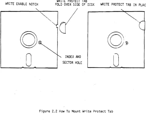
WRITE PROTECT FOR DISKETTES
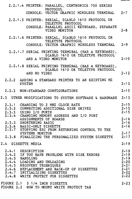
FIGURE 2.1 5 1/4 INCH DISKETTE
FIGURE 2.2 HOW TO MOUNT WRITE PROTECT TAB
2-15 2-15 2-15 2-16 2-16 2-16 2-17 2-17 2-19 2-19 2-19 2-19 2-20 2-21 2-21 2-22 2-22 2-23
SECTION III DAY TO DAY OPERATIONS
3.0 SUMMARY OF NORMAL START UP PROCEDURE 3.1 SUMMARY OF PROMPTS
3.2 POWER-ON 3. 3 LOAD MOOS
3.4 LOAD M.BASIC FROM MOOS
3.5 OTHER OPERATING SYSTEMS AND LANGUAGES 3.6 RETURNING TO MOOS FROM M.BASIC
3.7 RETURNING TO MONITOR FROM ANYPLACE
3.8 RETURNING TO MOOS (OR M.BASIC) FROM MONITOR MDOS (OR M.BASIC) IS ALREADY IN MEMORY
3.9 RETURNING TO MOOS OR M.BASIC EXECUTIVE FROM A ROUTINE RUNNING UNDER THAT EXECUTIVE
3.10 VIDEO COMMANDS 3.10.1 3.10.2 3.10.3 3.10.4 3.10.5 3.10.6 3.10.7 3.10.8 3.10.9
CLEAR SCREEN
SCROLL SCREEN UP ONE LINE BACKSPACE CURSOR
CONVERT TO REVERSE VIDEO
TAB CURSOR 8 SPACES TO THE RIGHT ELIMINATE CURSOR FROM THE SCREEN MOVE CURSOR TO TOP OF SCREEN
MOVE CURSOR DOWN, UP, LEFT, OR RIGHT RETURN CURSOR TO LEFT EDGE OF SCREEN 3.11 POWER-DOWN
SECTION IV MICROPOLIS DISKETTE OPERATING SYSTEM 4.0 INTRODUCTION TO MOOS
4.1 THE MOOS EXECUTIVE
4.1.1 ENTERING EXECUTIVE COMMANDS 4.1.2 EXECUTIVE STATEMENT FORMAT 4.1.3 CANCELING AN OPERATION 4.1.4 DISPLAY CONTROL
Rev. 8.3-A 7/1/79
4. 1. 5 EXPLICIT EXECUTIVE COMMANDS
4.1.5.1 THE COMP COMMAND 4.1.5.2 THE DUMP COMMAND 4.1.5.3 THE ENTR COMMAND 4.1.5.4 THE FILL COMMAND 4.1.5.5 THE MOVE COMMAND 4.1.5.6 THE SEAR COMMAND 4.1.5.7 THE SEARN COMMAND 4.1.5.8 THE CREATE COMMAND 4.1.5.9 THE DISP COMMAND 4.1.5.10 THE FILES COMMAND 4.1.5.11 THE FREE COMMAND 4.1.5.12 THE SCRATCH COMMAND 4.1.5.13 THE LOAD COMMAND 4.1.5.14 THE SAVE COMMAND 4.1.5.15 THE RENAME COMMAND 4.1.5.16 TYPE COMMAND
4.1.5.17 THE APP COMMAND 4.1.5.18 THE ASSIGN COMMAND 4.1.5.19 THE EXEC COMMAND
4.1.5.20 THE ~1ATH COMMAND
4.1. 5.21 THE PROMPT COt1MANO 4. 1. 5. 22 THE IN IT CO~1MAN D
4.2 MOOS DISK FILE I/O
4.2.1 TRACK INDEXED FILE STORAGE 4.2.2 FILE NAMES
4.2.3 FILE PROTECTION AND TYPE DEFINITION 4.2.4 FILE AND RECORD STRUCTURE
4.2.5 FILE ACCESS METHODS
4.2.6 COMPATIBILITY BETWEEN MOOS AND BASIC FILES
4.3 MOOS SHARED SUBROUTINES
4.3.1 CONSOLE AND PRINTER INPUT/OUTPUT SUBROUTINES
4.3.1.1 @CIN - CONSOLE INPUT 4.3.1.2 @COUT - CONSOLE OUTPUT 4.3.1.3 @CBRK - CONSOLE BREAK CHECK 4.3.1.4 @CDIN - CONSOLE DEVICE INPUT 4.3.1.5 @CDOUT - CONSOLE DEVICE OUTPUT 4.1.1.6 @CDBRK - CONSOLE DEVICE BREAK CHECK 4.3.1.7 @CDINIT - CONSOLE DEVICE INITIALIZATION 4.3.1.8 @LOUT - LIST OUTPUT
4.3.1.9 @LATN - LIST ATTENTION
4.3.1.10 @LDOUT - LIST DEVICE Ot~PUT
4.3.1. 11 @LDATN - LIST DEVICE ATTENTION
4.3.1.12 @LDINIT - LIST DEVICE rNITIALIZATION
4.3.1.13 @CCRLF - CONSOLE LINE FEED CARRIAGE RETURN 4.3.1.14 @LCRLF - LIST LINE FEED CARRIAGE RETURN 4.3.1.15 @ASSIGN - ASSIGN
Rev. 7 3/78
4.3.1.16 @CILINE - CONSOLE INPUT LINE 4.3.1.17 @HEXOUT - HEXADECIMAL OUTPUT
4.3.1.18 @HEXADDOUT - HEXADECI~~L ADDRESS OUTPUT
4.3.1.19 @HEXOUTSPC - HEXADECIMAL OUTPUT WITH SPACE 4.3.1.20 @SPACEOUT - SPACE OUT
4.3.1.21 @NLINEOUT - NEW LINE OUTPUT 4.3.1.22 @LINEOUT - LINE OUTPUT
4.3.2 TEXT LINE PARSING SUBROUTINES
4.3.2.1 @?ARAM - PARAMETER
4.3.2.2 @SKIPSPACE - SKIP SPACES 4.3.2.3 @SCAN - SCAN
4.3.2.4 @SEAR - SEARCH
4.3.2.5 @AHEXTBIN - ASCII HEX TO BINARY
4.3.3 THE FILE ACCESS ROUTINES
4.3.3.1 @CREATE - CREATE
4.3.3.2 @GFILESTAT - GET FILE STATUS 4.3.3.3 @DIRSEARCH - DIRECTORY SEARCH 4.3.3.4 @QPENFILE - OPEN A FILE
4.3.3.5 @CLOSEFILE - CLOSE A FILE
4.3.3.6 @RFILEINF - READ FILE INFORMATION
4.3.3.7 @SINXTRS - SET INDEX POSITION TO RECORD START 4.3.3.8 @RRECORDLEN - READ RECORD LENGTH
4.3.3.9 @RINXPOS - READ INDEX POSITION 4.3.3.10 @SINXPOS - SET INDEX POSITION 4.3.3.11 @INCINX - INCREMENT INDEX POSITION 4.3.3.12 @RFINXPOS - READ FROM INDEX POSITION 4.3.3.13 @RFINXPOSI - READ FROM INDEX POSITION AND
INCREMENT INDEX
4.3.3.14 @WTINXPOS - WRITE TO INDEX POSITION 4.3.3.15 @WTINX?OSI - WRITE TO INDEX POSITION AND
INCREMENT INDEX
4.3.3.16 @LOADDATA - LOAD DATA 4.3.3.17 @SAVEDATA - SAVE DATA
4.3.3.18 @DFINXPOSTEOR - DELETE FROM INDEX POSITION TO END OF RECORD
4.3.3.19 @DFINXPOS - DELETE FROM INDEX POSITION TO END OF FILE
4.3.3.20 @INCRECPOS - INCREMENT RECORD POSITION
4.3.4 FILE MANAGEMENT SUBROUTINES
4.3.4.1 @FREE - FREE 4.3.4.2 @RENAME - RENAME 4.3.4.3 @TYPE - FILE TYPE·
4.3.4.4 @SCRATCH - SCRATCH A FILE
Rev. 7 3/78
PAGE
4.3.5 PHYSICAL DISK ACCESS ROUTINES 4-33
4.3.5.1 @GETASEC - GET A SECTOR 4-34
4.3.5.2 @PUTASEC - PUT A SECTOR 4-34
4.3.5.3 @WRITESECTOR - WRITE A SECTOR 4-35
4.3.5.4 @VERIFYSECTOR - VERIFY A SECTOR 4-35
4.3.5.5 @SEEKTRACK - SEEK TO A TRACK 4-35
4.3.5.6 @RESTOREDISK - RESTORE THE READ/WRITE HEAD 4-35
4.3.6 PROCESSOR ORIENTED UTILITY ROUTINES 4-36
4.3.6.1 @HLADDA - ADD A TO HL 4-36
4.3.6.2 @INXM - INCREMENT ~'EMJRY 4-36
4.3.6.3 @LHLINDEXED - LOAD HL INDIRECT INDEXED 4-36
4.3.6.4 @LHLI - LOAD HL INDIRECT 4-37
4.3.6.5 @TRANSDHC - TRANSFER FROM DE TO HL FOR A COUNT OF C 4-37
4.3.6.6 @TRANSDHBC - TRANSFER FROM DE TO HL FOR A COUNT OF BC 4-37
4.3.6.7 @TRANSDHBCR - TRMtSFER FROM DE TO HL FOR A COUNT OF
BC REVERSE 4-37
4.3.6.8 @TRANSFILENAME - TRANSFER A FILENAME 4-38
4.3.5.9 @FILLZER - FILL ZEROES 4-38
4.3.6.10 @FILLSPC - FILL SPACES 4-38
4.3.6.11 @FILLA - FILL FROM THE A REGISTER 4-38
4.3.6.12 @COMPARE - COMPARE HL TO DE 4-38
4.3.7 EXTENDED 8080 INTEGER ARITHMETIC (16 BITS) 4-39
4.3.7.1 @DEADDHL - BC=DE+HL 4-39
4.3.7.2 @DESUBHL - SC=DE-HL 4-39
4.3.7.3 @DEMULHL - BC=DE*HL 4-39
4.3.7.4 @DEDIVHL - BC=DE/HL 4-40
4.3.7.5 @DEMODHL - BC=DE%HL 4-40
4.3.8 MESSAGE OUTPUT SUBROUTINES 4-40
4.3.8.1 @DISKERROR - DISK ERROR MESSAGES 4-40
4.3.8.2 @CLOSEFILES - CLOSE ALL FILES 4-41
4.3.8.3 @ERRORMES - ERROR MESSAGES 4-41
4.3.8.4 @MESSAGEOUT - MESSAGE OUTPUT 4-41
4.3.9 SYSTEM BUFFERS AND ENTRY POINTS 4-41
4.4 LINEEDIT - THE MOOS LINE EDITOR 4-43
4.4.1 ENTERING LINES TO LINEEDIT 4-43
4.4.2 KEYING IN A NEW TEXT FILE 4-44
4.4.3 ENTERING LINEEDIT COMMANDS 4-44
4.4.4 THE CLEAR COMMAND 4-45
4.4.5 THE NAME COMMAND 4-45
4.4.6 THE FILE COMMAND 4-45
4.4.7 THE AUTO COMMAND 4-45
4.4.8 THE PROMPT COMMAND 4.4.9 THE LOAD COMMAND 4.4.10 THE APPEND COMMAND 4.4.11 THE SAVE COMMAND 4.4.12 THE RESAVE COMMAND 4.4.13 THE LIST COMMAND 4.4.14 THE LISTP COMMAND 4.4.15 THE PRINT COMMAND 4.4.16 THE PRINTP COMMAND 4.4.17 THE TAB COMMAND 4.4.18 THE DELT COMMAND 4.4.19 THE RENUM COMMAND 4.4.20 THE SEARCH COMMAND 4.4.21 THE SEARCHALL COMMAND 4.4.22 THE CHANGE COMMAND 4.4.23 THE CHANGEALL COMMAND 4.4.24 THE EDIT COMMAND
4.4.24.1 ADVANCING THE EDIT POINTER
4.4.24.2 CHANGING THE NEXT CHARACTER - C 4.4.24.3 DELETING THE NEXT CHARACTER - D 4.4.24.4 INSERTING CHARACTERS - I
4.4.24.5 LISTING THE LINE IN THE EDIT BU~FER - L 4.4.24.6 SEARCHING TO A SPECIFIED CHARACTER - S 4.4.24.7 DELETING TO A SPECIFIED CHARACTER - K 4.4.24.8 QUITTING THE EDIT COMMAND MODE - Q 4.4.24.9 COMPLETING THE EDIT COMMAND
4.4.25 THE DOS COMMAND - EXITING FROM LINEEDIT 4.4.26 LINEEDIT FILE STRUCTURE
4.5 ZSM - Z-80 ASSEMBLER
4.5.1 HOW TO RUN ZSM 4.5.2 LANGUAGE ELEMENTS
4.5.2.1 CONSTANTS 4.5.2.2 OPERATORS 4.5.2.3 REGISTERS 4.5.2.4 PSEUDO-OPS
4.5.3 ASSEMBLY ERRORS 4.5.4 INSTRUCTION SET 4.5.5 TEST FILE FOR ZSM
Rev. 8.4-A 7/26/79
4.6 SYMSAVE UTILITY 4.7 FILECOPY UTILITY 4.8 DISKCOPY UTILITY 4.9 MOOS ERROR MESSAGES
4.10 COPYFILE UTILITY FOR SINGLE DISK 4.11 MICROPOLIS DEBUG
4.12 DEBUG-GEN UTILITY
SECTION V MICROPOLIS DISK EXTENDED BASIC
5.0 INTRODUCTION
5.1 ENTERING LINES TO THE BASIC INTERPRETER 5.2 ENTERING A PROGRAM
5.3 IMMEDIATELY EXECUTED LINES
5.3.1 THE EDIT COMMAND 5.3.2 THE RENUM COMMAND
5.3.3 THE r~ERGE COMMAND
5.4 DELETE COMMAND 5.5 LIST COMMAND 5.6 SAVE COMMAND 5.7 LOAD COMMAND 5.8 DISPLAY COMMAND 5.9 SCRATCH COMMAND 5 . 10 RUN COMMAND
5.11 INTERRUPTING A RUNNING PROGRAM 5.12 CONTINUING AN INTERRUPTED PROGRAM 5.13 PROGRAM TRACING COMMANDS
5.14 BASIC SYSTEM ERROR HANDLING 5.15 BASIC. CHARACTER SET
5.16 DATA
5.16.1 CONSTANTS 5.16.2 VARIABLES 5.16.3 OUTPUT FORMATS
Rev. 8 9/78
PAGE
4-68 4-69 4-69
4-71
4-74 4-75 4-92
5-1 5-1 5-2
5-3 5-3
5-4.1 5-4.3
5-3
5-4 5-4
5-5 5-5
5-6 5-6
5-7 5-7
5-8 5-8
5-9
5-9
5-9
PAGE
5. 11 OPERATORS 5-14
5.11.1 NUMERIC OPERATORS 5-14
5.11.2 STRING OPERATORS 5-14
5.11.3 RELATIONAL OPE~~TORS 5-15
5.11.4 LOGICAL OPERATORS 5-16
5.18 FUNCTIONS 5-11
5.18.1 INTRINSIC FUNCTIONS 5-11
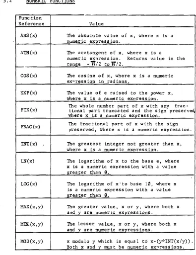
5.18.1.1 NUMERIC FUNCTIONS
ASS 5-18
ATN 5-18
COS 5-18
EXP 5-18
FIX 5-18
FRAC 5-18
INT 5-18
LN 5-18
LOG 5-18
MAX 5-18
MIN 5-18
t-IlD 5-18
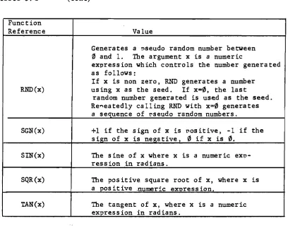
RNO 5-19
SGN 5-19
SIN 5-19
SQR 5-19
TAN 5-19
5.18.1.2 STRING FUNCTIONS
,
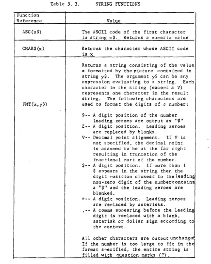
ASC 5-20
CHAR$ 5-20
FMT 5-20
INOEX 5-21
LEFT$ 5-21
LEN 5-21
MIO$ 5-21
MAX 5-21
MIN 5-21
REPEAT$ 5-21
RIGHT$ 5-21
STR$ 5-21
VAL
5-21VERIFY 5-21
5.18.1.3 SPECIAL FUNCTIONS
IN 5-22
PEEK 5-22
PGMSIZE 5-22
SPACELEFT 5-22
5.18.2 USER DEFINED FUNCTIONS 5-22
5.19 Expressions
5.19.1 Evaluation of Expressions 5.19.2 Numeric Expressions
5.19.3 String Expressions 5.19.4 Logical Expressions
5.20 BASIC Statements
5.20.1 DATA 5.20.2 DEF FN 5.20.3 DEF FA 5.20.4 DIM 5.20.5 END 5.20.6 EXEC 5.20.7 FLOW 5.20.8 FOR 5.20.9 GOSUB 5.20.10 GOTO 5.20.11 IF •• THEN 5.20.12 INPUT 5.20.13 LET 5.20. 14 MEMEND 5.20.15 NEXT 5.20.16 NOFLOW
~.20.17 ON •• GDTO 5.20.180N •• GOSUB 5.20.19 OUT
5.20.20 POKE 5.20.21 PRINT 5.20.22 READ 5.20.23 REM 5.20.24 RESTORE 5.20.25 RETURN "5.20.26 SIZES
5.20.27 STOP 5.20.28 STRING
5.21" BASIC DISK FILE I/O
5.21.1 Disk Files
5.21.2 Disk File Commands
5.21.2.1 DISPLAY 5 • 21. 2 • 2 LOAD 5.21.2.3 PLOADG 5.21.2.4 SAVE 5.21.2.5 SCRATCH
5.21.2.6 CHAIN 5.21.2.7 LINK
Rev. 7 3178
5-33
5 ... 33 5-33 5-34 5-35
5-36
Rev. 7 3/78
5.21.3 Disk I/O Statements 5.21.3.1 OPEN
5.21.3.2 PUT 5.21.3.3 GET 5.21.3.4 CLOSE 5.21.3.5 AITRS 5.21.3.6 EOF
5.21.3.7 FREESPACE 5.21.3.8 GETSEEK 5.21.3.9 PUTSEEK 5.21.3.10 RENAME 5.21.4 Disk I/O Functions
AITR ERR ERR$ NAME RECGET RECPUT SIZE TRACKS FREETR
5.22 BASIC PRINT FILE OUTPUT
5.22.1 Printer Related Language Features 5.22. 1. 1 OPEN
5 . 22. 1. 2 PUT 5.22.1.3 CLOSE 5.22.1.4 ENDPAGE 5.22.1.5 ASSIGN 5.22.1.6 LISTP 5.22.1.7 PAGESIZE
5.22.2 Notes on Printer Related PrograJmling 5-54.1 5-55 5-57 5-60 5-60 5-61 5-61 5-62 5-62 5-62 5-63 5-63 5-64 5-64 5-64 5-64 5-64 5-64 5-64 5-64 5-64 5-65 5-65 5-65 5-66 5-66 5-67 5-67 5-69 5-69 5-70 5.22.2.1 Separating Print Files 5-70
and Interactive Messages
5.22.2.2 Paginating Print Files 5-73 5.22.2.3 Spooling Print Files to 5-76
Disk for Later Output
5.22.2.4 Draining File Output to A 5-76
Nun Device
SECTION VI DISK SUBSYSTEM THEORY AND DIRECT PROGRAMMING
FIGURE 6.1 5 1/4 INCH DISKETTE
6.0 INTRODUCTION
6.1 FUNDAMENTALS OF THE FLEXIBLE DISK: MEDIA
6 • 2 HARDWARE FUNDAMENTALS
6.3 CONTROLLER REGISTERS 6.4 DISK OPERATIONS 6.5 ERROR HANDLING 6.6 DISK DRIVER
APPENDICES
A - BASIC ERROR MESSAGES
B - BASIC UTILITY PROGRAM
C - ACCESSING DISKCOPY FROM BASIC
o -
SUMMARY OF MOOS ERROR MESSAGESE - RES. I/O SOURCE LISTING
F - MICRO POLIS DISK BOOTSTRAP
G - "FEATURES" PROGRAM TO OPTIONALLY SHORTEN BASIC
H - INTERFACING TO A CENTRONICS PRINTER
I - TROUBLE SHOOTING IF MOOS DOES NOT LOAD
J - GAMES AND DISPLAYS ON THE MOOS SYSTEM DISKETTE
PAGE
6-1
6-1
6-3 6-3 6-7 6-9 6-13
6-20 6-21
K - CHANGING MICROPOLIS BOOTSTRAP ROM AND DISK I/O ADDRESS
L - CHANGING CLOCK RATE TO 2 MHZ
M - WRITING A CONSOLE PHYSICAL I/O ROUTINE
N - WRITING A PRINTER PHYSICAL I/O ROUTINE
o -
REASSEMBLING AND SAVING THE RES MODULEP - MAP OF I/O PORTS
Q - MEMORY DIAGNOSTICS
appendices
E-1 Add remark: RES. I/O has been altered for the re-arranged board addressing. Hence, i f you need it, list it using LINEEDIT, or assemble it· using ZSM from the 8.5 MOOS System Diskette.
H-1 The instructions in this appendix only apply to the Bitstreamer I board. 1-1 Change C000 to E000.
J-1 Change FLASH7 to FLASH8.
K-1 and K-2 The standard location is from F800-FBFF. A single jumper
at
W4 is the standard...
0-1 If the system has a Bitstreamer II board controlling a printer, use Bitstreamer base address of 0 for serial ports at 2 and 3, and use base address 4 for' ports 6 and 7 (to control the printer.) (Do not worry about control of a serial
terminal, if used. 'Ihis is handled by the Extended Systems 'Monitor~) .
If controlling a printer out of a Bitstreamer II parallel port, then do not use the standard drivers.
P-2 Add the following: Ports 8 and 9 are Bitstreamer II parallel ports. 40 is 64K and 16K bank select. 10-14 are used by the Vector Graphic Precision Analog Board. The Tarbell Disk uses Fe as well as its other port addresses •.
Q-1 and Q-2 Change 1f48K" to "56K. If To use the T canmand, enter T 0IiH"" DFFF. MAP
uses scratch pad FC00 to FDFF in all systems now. Add explanation of WoRM, taken from the explanation above in this errata. ~ ...
. .
I GENERAL INFORMATION 1.0 GENERAL DESCRIPTION OF SYSTEM AND SUBSYSTEMS
Your system is a general purpose microprocessor based computer. It is delivered by Vector Graphic completely assembled and fully tested, including both hardware and operating system software, and including two quad density mini-floppy disk drives.
1.0.1 STANDARD HARDWARE AND SOFTWARE
1) Chassis with power supply and
1B
slot fully shielded S-100 motherboard;2) 4 MHz
Z-Bo
CPU board;3) Two quad density Micropolis mini floppy disk drives, allowing 1232 256-byte sectors per diskette.
4) Disk controller board; 5) Bitstreamer I/O board;
6) 4BK Dynamic RAM board;
I
7) PROM/RAM III board, with space for 12K of EPROM and the
I
ability to pr.ogram EPROM's (see the PROM/RAM III boardmanual).
B) The Vector Graphic Extended Systems Monitor, on PROM;
9) Two copies of the MOOS System Diskette, each containing:
.-a) The Vector Graphic-enhanced Mlcropolis Disk Operating System - MDOS - a complete floppy diskette operating
system, including a
Z-Bo
Assembler, an editor, a debugger,I
and several other utilities (see Ch.4);b) Micropolis BASIC (see Ch. 5);
c) A number of games and video displays (see Appendix J.) 1.0.2 OPTIONAL COMPONENTS AND SOFTWARE
Your MZ can be configured with various optional peripherals. Section 2.2 of this manual lists the configurations of printers and consoles considered "standard" for the MZ, and gives the components such as interface boards and cables needed for each configuration. In addition to the configurations discussed in Section 2.2, the following components can optionally be added to an MZ:
1) Additional Bitstreamer I/O board(s), such as the Bitstreamer II having three serial ports, two parallel ports, real-time
clock, and Z-80 inte~~upts.
2) Additional memo~y boa~d(s);
3) Othe~ S-100 compatible boa~ds f~om Vecto~ G~aphic o~ othe~
sou~ces.
4) 2 additional Mic~opolis mini-floppy disk d~ives;
5) Othe~ ope~ating system and language softwa~e.
Contact you~ deale~ fo~ mo~e info~mation on adding components to the system.
1.1 MICROPOLIS FLOPPY DISKETTE SUBSYSTEM SPECIFICATIONS
1.1.1 PERFORMANCE
Capacity pe~ d~ive: 315K bytes, fo~matted
T~ansfe~ ~ate: 250K bits/second
Ave~age ~otational latency time: 100 milliseconds
Access time - t~ack-to-t~ack : 30 milliseconds settling time: 10 milliseconds
Head load time: 75 milliseconds
Head positione~: steppe~ moto~ with lead-sc~ew d~ive D~ive moto~ sta~t time: 1 second
Rotational speed: 300 RPM
Reco~ding density 5248 bits pe~ inch (BPI)
Reco~ding mode: MFM
T~ack density: 100 t~acks pe~ inch (TPI) Su~faces used pe~ diskette: 1
1.1.2 DRIVE RELIABILITY
MTBF
MTTR 8000 0.5 h~s h~s. ..
Media life Head life
3 X 10 EXP 6 passes on single track 10 EXP 4 hI'S.
Soft e~~o~ ~ate Ha~d e~~o~ ~ate
Seek e~ror rate
1 in 10 ElP 9 1 in 10 EXP 12 1 in 10 EXP 6
1-2 Rev. 8.4-A 7/26/79
1.2 HEXADECIMAL NOTATION
In this manual as in most microcomputer literature, the base 16 number system is used for all references to memory locations, instruction codes, character codes, and so on. If you are not familiar with it, you will soon find that the hexadecimal system is the most natural way to express these numbers when dealing with a computer that stores data as groups of 8 binary digits (bits) and memory addresses as groups of 16 bits. Hex numbers will be indicated by an upper case H following the ,digits. Remembering a few key values will make things a great deal easier:
HEX NUMBER DECIMAL VALUE JARGON BINARY BITS
A 10 4
B 11 4
C 12 4
D 13 4
E 14 4
F 15 4
10 16 5
FF 255 8
100 256 9
3FF 1,023 10
400 1,024 lK 11
FFF 4,095 12
1000 4,096 4K 13
4000 16,384 16K 15
8000 32,7613 32K 16
FFFF 65,535 64K-l 16
The familiar rules of arithmetic work just the same in hex as in decimal:
10 HEX (TRIVIAL)
40) 400 or
16 DECIMAL (MORE DIFFICULT) 64) 1024
64 384 384
---u
1.3 OPERATING SYSTEM SOFTWARE
1.3.1 VECTOR GRAPHIC EXTENDED SYSTEMS MONITOR
The first program the user comes into contact with after turning on the system is the Vector Graphic Extended Systems Monitor.
(Exception: this is not true for MEMORITE systems.) It is entirely stored on non-volatile PROM. Note that this use of the term "Monitor" has a meaning entirely different than the term "monitor", which refers to a piece of hardware, namely a stand-alone video display. (NOTE: in the MEMORITE system, the Extended Systems
Monitor is not encountered unless you press the RESET key~ or touch the ESC key while the system is under control of MOOS or another NON-word processing operating system.)
The Monitor consists of two parts: first, the Extended Systems Monitor Executive, which allows the operator, through special commands, to manipulate and display memory data and to jump to some other program~ second, a program used to control console I/O.
You know the Extended Systems Monitor Executive is in control of the system when the Monitor prompt (*) appears on the left edge of the screen. The operator is then e~pected to enter one of the commands available for manipulating or displaying memory or jumping to another program. Most often, the operator will use the command which calls up a full operating system and then transfers control to it, and out of the Monitor.
Regardless of whether executive is in control of the system at any given time, the Monitor console I/O routines, though invisible to the operator, are continually being called on to control the console. (Exception: when MEMORITE or the Word Management System are doing word processing, the Monitor is not used to control the console. Instead, the word processing software in these two systems handles this task.)
Some of the Monitor's features and commands are explained where relevent in this manual. A complete description is included as a separate manual with your system.
1.3.2 PROGRAM DEVELOPMENT SOFTWARE - "PDS"
The operating system found on the MOOS Systems Diskette included with the system is the Micropolis Diskette Operating System (MDOS).
MOOS includes an assembly language program development package. Also found on the MOOS Systems Diskette is Micropolis Disk Extended BASIC (often called just M.BASIC). MOOS and M.BASIC together give all the functions a programmer may need for the development of either assembly language or BASIC programs.
1.3.3 ELEMENTS OF MOOS
MOOS consists of an executive program, a group of "shared" subroutines available to user programs as well as being used by MOOS, and various utilities which include assembly language program development tools.
The MOOS executive program allows the user to control computer system operations from the system console. It provides commands for memory management, file management, I/O control and program control.
The shared subroutines include those that provide for console and printer character I/O, buffered line I/O, text line parameter parsing, sequential and random file access, file management,
physical diskette access, and 16 bit interger arithmetic. There are also a number of processor oriented utility subroutines.
The MDOS utilities are:
ZSM - a two pass, aoaO/SOS5/ZS0 disk to disk assembler program.
LINEEDIT - a line number oriented assembly language text editor with character-within-line editing and global search and change capabilities.
FILECOPY - a utility that copies disk files.
DISKCOPY - a utility that makes an exact copy of an entire
diskette.
SYMSAVE - a utility that creates a source file of symbol equate statements from the symbol table left in memory immediately after an assembly by the ZSM assembler.
DEBUG - a u t i l i t y that facilitates checkout and debugging of a080/S0a5 machine language programs. It cannot be used if zao code which is not part of the a080 set is used.
1.3.4 ELEMENTS OF M.BASIC
M.BASIC is a complete, self-contained software package that provides total support for BASIC programming. When M.BASIC is loaded you have at hand a powerful set of tools for developing, testing, executing and maintaining BASIC programs.
Program lines may be as long as 250 characters in length and may include multiple statements. The maximum line number is 65529.'
M.BASIC has 12 immediate mode commands, including: SAVE a file, LOAD a file, DISPLAY the file directory, SCRATCH a file, LIST a program, DELETE lines from a program, RUN a program, CNTL/C to
interrupt a r~nning program, CONT to continue an interrupted
program, CNTL/U to cancel an input line, and FLOW and NOFLOW to enable and disable the flow trace debugging aid.
M.BASIC supports 6 distinct data types, including integers, integer arrays, floating point numbers in the range lE-61 to lE62-1, string arrays, floating point arrays, and character strings up to 250 characters long. Integer and floating point arrays may have up to 4 dimensions. String arrays may have up to 3 dimensions plus a length parameter.
A unique SIZES statement enables you to select the precision of numeric variables up to 60 digits for simple arithmetic and 20 digits for transcendental functions. The system defaults to 8
digits for real numbers and 6 for integers.
M.BASIC supports numeric operators for addition, subtraction, multiplication, division, integer division, and exponentiation.
There are relational operators to compare numbers or strings and the logical operators AND, OR, and NOT. String concatenation is also available.
Numeric functions include ABS, ATN, COS, EXP, FIX, FRAC, INT, LN, LOG, MAX, MIN, MOD, RND, SGN, SQR, and TAN.
String functions include ASC, CHAR$, FMT, INDEX, LEFT$, LEN, MID$, MAX, MIN, REPEAT$, RIGHT$, STR$, VAL, VERIFY.
The unique FMT (X,Y$) function is the key to a powerful formatted output capability. It returns a string which is the value of X
formatted per the image defined by format string Y$.
The DEF FN statement is provided to allow construction of user defined functions. An assembly language function may be accessed by using the DEF FA construction.
Standard statements in BASIC include CHAIN, DATA, DEF, DIM, EDIT, END, EXEC, FOR-NEXT-STEP, GOSUB, GOTO, IF-THEN, INPUT, LET, MEMEND, MERGE, NOFLOW, FLOW, ON-GOTO, ON-GOSUB, OUT, PLOADG, POKE, PRINT, READ, REM, RENUM, RESTORE, RETURN, SIZES, STOP, and STRING.
The CHAIN is a true chain that passes variables from the current program segment to next one loaded from disk.
EXEC is a unique statement that allows a string variable or constant to be executed as if it were a predefined program line.
Data file programming in M.BASIC is simple. Files can be opened simultaneously for both sequential and direct (random) access in both read and write modes. Up to 10 files can be open at one time. A CLEAR option allows a file to be opened for rewrite instead of append. An END option provides an on-endfile-goto capability. An ERROR option provides an on-error-goto capability.
Data is written to and read from files using GET and PUT statements with variable lists that allow a mixture of numeric and string
variables. '
The file I/O structure also extends to printer and console output files to afford a high degree of device independence. Additional options on the OPEN statement facilitate the pagination of output reports.
Also provided is a BASIC Utility program that provides for initializing diskettes, saving M.BASIC on a BASIC-only diskette, and examining and changing RAM memory. In addition, there is a utility called FEATURES which allows you to shorten M.BASIC by eliminating some of the features needed only for program development, but not for running production programs.
1.3.5 OTHER OPERATING SYSTEMS
Other operating systems and higher level languages are available
from Vector Graphic. These will not be discussed here. (See the literature accompanying this manual.) MDOS and M. BASIC meet the needs of the large majority of users.
1.3.6 RESIDENT PROGRAMS
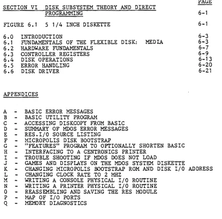
MDOS and M.BASIC share the Extended Systems Monitor. They also share a common program module called RES. This module contains among other routines, the printer and diskette I/O routines, and some of the console I/O routines.
Also shared is the ROM resident Disk Bootstrap program, (which is what the Monitor uses in order to call up MDOS), and the Disk Controller, (which is simply memory space needed to handle the diskette drives.)
These routines are always resident in the computer memory when either MDOS or M.BASIC is running. For interested users, listings will be found in Appendix E for the I/O portion of RES, Appendix F for the Disk Bootstrap program, and the Extended Systems Monitor manual for the Monitor.
In contrast, MDOS and M.BASIC overlay each other; that is, they are assigned the same area of memory; only one can be in memory at any given time. Commands are provided for leaving one and calling up the other.
Fig. 1.1 illustrates the relationships between the various system programs. Programs which are always in memory when MDOS or M.BASIC is used are in the center.
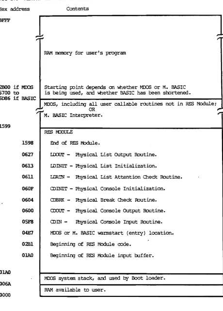
Fig. 1.2 gives the addresses of the various programs and important memory locations in your system. No particular operating system is shown.
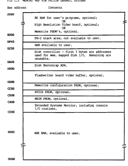
Fig. 1.3 gives addresses for MDOS and M. BASIC. Note that this operating system software fits into the unassigned memory area in Fig. 1.2.
I-'
I
00
jg <:
•
00
I-'
tv "-01 "-...,J \0
FIGURE 1.1 MZ SOFTWARE STRUCTURE USING MOOS
MOOS EXECUTIVE
ASSEMBLY LANGUAGE APPLICATION PROGRAMS
SYMSAVE
EXTENDED SYSTEMS MCNlTOR, . wi th
ODnsOle physical I/O routines
DISK B<XJISTRAP 101, and
DISK CXNrIPLLER ADDRESSES
-
---RES MODULE
Cot-MlN CONSOLE AND PRINTER I/O
(Console
physical I/O branches to Monitor.)
COMttlN DISK FILE STRUCTURES
DISK EXTENDED BASIC
INTERPRETER
FIG 1.2 MEMORY M.~ FOR VECroR GAAPHIC SYSTEMS
Hex address
£000
DF40
DCOO
DN)O
0800
0000
0::00
caoo
C400
cooO
8000
0000
Rev. 8.1
1
...
;.,~1.10
T
2/5/79
Contents
8K RAM for userts programs, optional;
OR
High Resolution Video board, optional; OR
Memorite PRQMt s , optional.
PR-2 stack area, not available to user. RAM available to user.
Disk controller - first 3 bytes are addresses
used for memo mapped disk I/O. Remaining are
unusable.
Disk Bootstrap ROM.
Flashwriter board video buffer, optional. Memorite configuration PBQM, optional. EVIOS ProM, optional.
MZOS PROM, optional.
EXtended Systems Monitor, including console I/O routines.
48K RAM, available to user.
1-9
1
/"",.'.1
FIG 1.3 MEMORY MAP FOR MOOS AND M. BASIC
Hex address
BFFE'
2000 if MJ:X:S 5700 to
1
5086 i f BASIC
Contents
RAM. lIBOC)ty for user I s program
Start in; FOint depends on whether MOOS or M. BASIC is l::Jein;J used, an:l \'tlether BASIC has been soortened.
MOOS, includin;J all user callable rootines not in RES Module~
~ OR
M. BASIC Interpreter.
1599
1598
0627
0613
0611
060F
0604
0600
05F8
04E7
0281
OIAO
OIAO
006A
0000
RES mroLE
End of RES r-txlule.
LiXlUI' - Physical List OUtput Routine.
LDINrr - Physical List Initialization.
LDA.TN - Physical List Attention Chec.1<:: Routine.
CDINIT - Physical Console Initialization.
CDBRK - Physical Break Check R::>utine.
CIXX.JI' - Physical Console OUtput Routine.
<DIN - tbysical Console Input Routine.
MIX:S or M. BASIC warmstart (entry) location. 8eginnin;J of RES Module code.
Beginnin;J of RES M:ldule input bJffer.
MOOS system stack, an:l used by Boot loader.
RAM available to user.
1-10 Rev. 8.1 2/5/79
1.4 MDOS SYSTEM DISKETTE
This revision of the User's GUide to Vector Graphics Systems Using
MDOS corresponds to MOOS System Diskette
8.4,
(and minor revisionsI
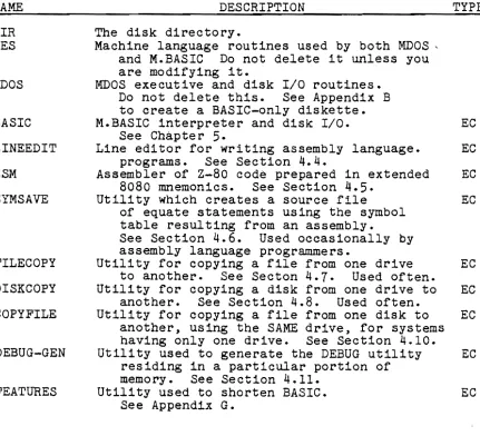
~t labeled 8.4.1, 8.4.2, etc.) Following is a list of the fileson this diskette:
(Under TYPE, "EC" means the file is stored in executable machine language code and it will be executed immediately if you type its name after the MDOS prompt. "AL" means the file is stored in assembly language source code. You must first assemble it using ZSM before i t can be executed by the computer. "Btt means the file is stored in the M.BASIC language. It will be executed by using the M.BASIC interpreter explained in chapter
5.)
NAME
DIR RES
MDOS
BASIC
LINEEDIT
ZSM
SYMSAVE
FILECOPY
DISKCOPY
COPYFILE
DEBUG-GEN
FEATURES
DESCRIPTION TYPE
The disk directory.
Machine language routines used by both MOOS, and M.BASIC Do not delete it unless you are modifying it.
MOOS executive and disk I/O routines. Do not delete this. See Appendix B to create a BASIC-only diskette.
M.BASIC interpreter and disk I/O. EC
See Chapter
5.
Line editor for writing assembly language. EC programs. See Section 4.4.
Assembler of Z-80 code prepared in extended EC 8080 mnemonics. See Section
4.5.
Utility which creates a source file EC
of equate statements using the symbol table resulting from an assembly.
See Section 4.6. Used occasionally by assembly language programmers.
Utility for copying a file from one drive EC to another. See Seeton 4.7. Used often.
Utility for copying a disk from one drive to EC another. See Section 4.8. Used often.
Utility for copying a file from one disk to EC another, using the SAME drive, for systems having only one drive. See Section 4.10.
Utility used to generate the DEBUG utility EC residing in a particular portion of
memory. See Section 4.11.
Utility used to shorten BASIC. EC
See Appendix G.
NAME
SYSQ1, and SYSQ2 UTILITY RES. I/O DIAB DIAB4 CENT CENT4 DECW DECW4 SAVERES NOESCAPE MDIAG MAP FLASH7 PROM STARTREKG CIVILWAR LUNAR FINANCE
DESCRIPTION TYPE
Assembly language source code containing the AL names of all MOOS shared subroutines,
equated to their addresses. Used
in assembly language programs calling those routines. See Section 4.3. Used from time to time by assembly language programmers.
A utility used to initialize diskettes, create B BASIC-only diskettes, and examine memory.
See Appendix B.
The source code file of the I/O routines in AL RES. Used to rewrite the I/O routines if using non-standard peripherals.
See Appendices M, N, and O.
Routine for interfacing to Diablo-protocol EC printers if the Bitstreamer board is
addressed for ports 0 -
3.
Overlays directly over RES in memory.See Section 2.2.2. Not
needed after RES is saved on diskette.
Same as DIAB, but Bitstreamer is at 4 -
7.
EC Same as DIAB, but for Centronics printers. EC Same as CENT, but Bitstreamer is at 4 -7.
EC Same as DIAB, but for teletype-protocol ECprinters.
Same as DECW, but Bitstreamer is at 4 - 7- EC Utility used to save on disk the machine EC
language version of the I/O portion of the RES Module. See Section 2.2.0. Not
needed after the RES Module is finalized.
Utility which stops the ESC key from causing EC control to be passed to the Systems Monitor. See Section 2.3.7. Not needed after used once.
Utility used to check the computer's memory. EC See Appendix Q. Do not delete this.
Utility which tells what kind of memory EC (RAM, ROM or nothing) is in the system
at each address. See Appendix Q. Useful when servicing a system.
Demonstration of the graphics capability of EC the Flashwriter II board. See Appendix J. Dealers use often.
Utility used with the PROM/RAM III board to EC program EPROM's. See PROM/RAM III manual. The Star Trek game. See Appendix J. B
Dealers use often. Others if they like it.
Another game. See Appendix J. B
Another game. See Appendix J. B
Day-to-day financial calculations.
See Appendix J. Used often if you need it. B
To obtain a list of the files on your diskette, to see what is actually there, turn the machine on. mount the system diskette in drive 0 (right-hand drive), type B after the Monitor prompt (*), type FILES after the MOOS prompt (5), and then press the RETURN key. The interaction looks like this on the screen:
*B
Vector MZ MOOS
x.xx
)FILESOIR 03 0000
RES 03 0014
The left-hand number refers to the file type, explained in Section 4.2.3. The right-hand number gives the length of the file in sectors. Both numbers are in hexadecimal (base 16).
The list is long and will roll past the edge of the screen. To stop i t at any point. depress control-S (CTRL key and S at the same time.) To start i t up again, depress the spacebar.
If you have a printer which is up and running with your system, you can print the directory by typing ASSIGN 2,3 (return), before you type FILES. After the directory is printed, type ASS.~I~G~N~2~z~2 (return} to turn the printer off again. "(return) U means press the
RETURN Key.
II INSTALLATION, CONFIGURING PERIPHERALS, AND USE OF DISKETTES
2.1 INSTALLATION
For turn-key systems (that is, all internal wiring and software modifications have been done prior to delivery), just plug in external cables to the sockets on the rear panel of the mainframe. End users: if sockets are not labeled and choice is not obvious, ask your dealer.
Por non-turn-key systems, refer to Section 2.2 for directions on setting up peripherals, interface boards, cables, and interface software. For systems with which a printer will be used, it may be desirable to first set the system up as if there were no printer , test it as explained below, then complete the setting up procedures for the printer. Section 2.2 separates the 2 stages.
When ready to test the system, do as follows:
1. Turn the power key on the front panel and then turn on peripherals. The Monitor prompt
*
should appear on the screen. (Exception: in MEMORITE systems, depress RESET on the front panel after turning the power on. The Monitor prompt should then appear.)2. Enter N on the keyboard. This is a memory test which also functions as a test of the console. After a few seconds a hexadecimal number should appear. It indicates the first memory address where no memory hardware is located. In normal systems with 48K of RAM, the number should be COOO.
3. Insert and mount the MOOS Personalized System Diskette in drive
o.
Drive 0 is the right-hand drive. The left-hand drive is drive 1. Refer to Section 2.4 for how to insert, mount, and in general handle diskettes.4. Enter B. This causes MOOS to be loaded and take control. This will be indicated by the MOOS sign on message and the MOOS prompt: >.
5. To test a separate printer , if any, first make sure there is paper in the printer. Then, enter ASSIGN 2,3 (return), followed by FILES (return). (The expression (return) always means npress the RETURN key.n). A list of the files on the System Diskette will be printed.
When the system is working properly, refer to Chapter 3 for a complete description of normal operating procedures, and to Section 2.4 for instructions on the handling and maintenance of diskettes. Do not neglect either Section 2.4 or Chapter 3 as they contain information which is not effectively acquired by trial and error alone. Section 2.3 describes various modifications which can be made to the hardware.
alone. Section 2.3 describes various modifications which can be made to the hardware and systems software.
2.2 CONFIGURING THE MZ - THIS SECTION FOR NON-TURN-KEY SYSTEMS ONLY 2.2.0 MODIFYING THE RES MODULE
At various points in this chapter (or in related appendices) you will be instructed to carry out procedures which modify the RES
Module. The most common of such procedures are the Software Implementation Procedures found in section 2.2.1 under each of the standard configurations. (These Software Implementation Procedures are used only if a printer is implemented.)
To carry out any procedure which modifies the RES Module, turn the system and all, peripherals on. In MEMORITE systems, depress the RESET button next. Then insert and mount the Personalized MDOS System Diskette in drive O. Do not use the Master MDOS System Diskette. This diskette should never be altered and only used for emergency back-up. After the Monitor prompts with
*,
enter B. This "boots up" MOOS, as indicated by the MOOS sign-on message and MOOS prompt:>.
Now proceed with the given procedure.Note that in all software procedures, "(return)" means "press the RETURN key."
The user may be instructed to enter a command, such as DIAB4 (return). Whenever such a command is entered, the system will respond by displaying the MOOS sign-on message again, or at least the MOOS prompt
>.
A step will be found which commands "Save the RES Module on Personalized System Diskette." This is accomplished as follows: Make sure the Personalized MDOS System Diskette is inserted and mounted in drive
o.
Then under MDOS type SAVERES (return). .The drive should write on the diskette. The RES Module is now saved on the Personalized MOOS System Diskette.Important: You may want to do several different procedures, each of which terminates with saving the RES Module. You are definitely free to do any group of them at one Sitting, and then save the RES Module as described above ONCE at the end of the session, in order to save trOUble. Alternately, you may of course save the RES Module after each such procedure, if desired.
Note: SAVERES is a utility which saves on diskette the I/O portion of the RES Module, in machine language form. The block of code which is saved corresponds to the code found in the source listing called RES. I/O, plus a few bytes before and after. In the rare case you have modified the RES Module outside of the I/O portion, then you must use the following alternate steps to save the RES Module: Under MDOS, enter TYPE "RES" 0 (return) SCRATCH "RES" (return) SAVE "RES" 2B1 1598 3 (return).
Rev. 8.4-A 7/26/79 2-2
2.2.1 STANDARD CONFIGURATIONS
At this time, Vector Graphic supplies the interface hardware and software to support several different configurations of main peripheral devices, that is, printers, keyboards, video displays, and terminals. This section is concerned with identifying these standard configurations, and explaining how they are implemented.
If the peripheral device desired is not found among the standard configurations, refer to Section 2.2.3.
The information is collected in the following pages. Each section is concerned with one configuration. Each configuration is a selected group of peripherals. Peripherals are listed as generic types, (upper case lettering). Specific makes are given as examples,
(lower case lettering). The user is not limited to these examples, but can use any model that falls within the given generic description.
To use these charts. find the configuration desired. When ordering an HZ or other Vector Graphic computer, order it with the components listed as well as the peripherals desired if supplied by Vector Graphic. (Since all systems are always delivered with one Bitstreamer board and an I/O cable, do not explicity order these items.)
I f no printer is being used. find the desired configuration ignoring the type of printer listed. For this purpose, refer only to those configurations whose .. headings are NOT preceded -by asterisks(*). Then, only order ~he parts and carry out the steps shown WITHOUT asterisks.
If a printer is being added to an existing system. find the desired configuration, then only order the parts and carry out the ~teps
shown WITH an asterisk (*). To obtain a useful summary of the issues involved with printers, see seciton 2.2.2
Some systems may already be partially configured at the factory or by intermediaries, so that you need order and set up only the components not already included. For example, "System Btl is an MZ with the Vector Graphic Mindless Terminal and Flashwriter II board. All you have to add is a printer. Your choices would be the configurations in Sections 2.2.1.4 and 2.2.1.6 for Centronics or Diablo-type printers respectively. MEMORITE is even simpler than a System B. Just do the Soft~re Implementation procedure in Section 2.2.1.6, using the DIAB4 command.
Flashwriter Board: The charts refer to a "Flashwriter Board." Order a Flashwriter I for 16 x 64 display and Flashwriter II for 80 X 24 display. When ordering an Extended Systems Monitor for use with one of these boards, always state which i t is for.
When your system and/or components are delivered. refer again to the chart. Perform the implementation procedures listed in order to implement the desired configuration.
*
2.2.1.1 Printer: PARALLEL, CENTRONICS 700 SERIES PROTOCOL.Console: SERIAL VIDEO TERMINAL.
Example: Parallel Centronics matrix printer (700 Series), and Hazeltine terminal.
Interface Components Required
1. Option C Extended Systems Monitor, on PROM.
*
2. Centronics interfacing kit3. Bitstreamer board and I/O cable (no need to order; included in system automatically.)
Hardware Implementation Procedures
*
1. Install the Centronics interfacing kit as instructed in Appendix H. Make sure there is an I/O cable connected at one end to J3 on the Bitstreamer board and at the other end installed in one of the cutouts at the rear of the mainframe.2. Plug the external terminal cable into the socket on the rear of the mainframe which is wired to the 6 pin molex connector on the Bitstreamer board.
*
3. Plug the printer cable into the socket which is wired to J3 on the Bitstreamer board.Software Implementation Procedures
*
1. Under t1DOS, enter CENT (return).*
2. Save RES Module on Personalized System Diskette.2.2.1.2 Printer: SERIAL, DIABLO 1610 OR TELETYPE PROTOCOL.
Console: SERIAL VIDEO TERMINAL.
Example: Printer: if Diablo protocol - Diablo 1610 or 1620, Qume Sprint 5, or NEC Spinwriter; if Teletype protocol -Decwriter, Teletype, or TI 810 or 820.
Console: Hazeltine terminal.
Interface Components Required
1.
2.
*
3.*
4.Option C Extended Systems Monitor, on PROM
Bitstreamer board and I/O cable (no need to order; included in system automaticelly.)
A second Bitstreamer board A second I/O cable
Hardware Implementation Procedures
*
1. Jumper one of the Bitstreamer boards so that i t is readdressed for ports 4 - 7 rather than the original 0 -1. Instructions will be found in the Bitstreamer UserlsManual. This board will be used to control the printer.
*
2. Make sure that the printer is set for its highest speed,(1200 baud for Diablo 1610 protocol), and that its parity
setting is MARK parity. Check the printer manual if necessary. Some printers such as the Diablo require a
jumper on internal circuitry to increase from 300 baud to 1200 baud.
*
3. Make sure that the Bitstreamer board is set for the same speed as the printer. This is set on a dipswitch on theupper left-hand corner of the board. Press the
appropriate switch in and upward and make sure all other switches are pressed downward.
4. Connect one of the I/O cables to J3 on one of the Bitstreamer boards. Install the 2S pin socket on the other end of the cable in a cutout at the rear of the mainframe.
*
S. Do step 4 for the second Bitstreamer and I/O cable.*
6. Plug the printer cable into the socket connected to the readdressed Bitstreamer.7. Plug the terminal cable into the socket connected to the normal Bitstreamer. IMPORTANT: Some terminals will not operate if they are connected to all 2S pins, because some of the pins of J3 on the Bitstreamer have functions other than serial communications. If your terminal does not operate after connecting it to all pins, then connect only the essential ones. Example: the Hazeltine 1400 will
function only if a 3-line cable is used, connecting,pins 2,3, and 7. A 2S pin ribbon connector will not work. Other terminals may require additional pins, but again not
all 2S. Refer to the Bitstreamer board manual if necessary for definitions of each of the pins on the backpanel connector.
Software Implementation Procedures
*
1. Under MDOS, if printer uses Diablo protocol, enter DIAB4 (return); if printer uses Teletype protocol, enter DECW4 (return).*
2. Save RES Module on Personalized System Diskette.*
2.2.1.3 Printer: PARALLEL, CENTRONICS 700 SERIES PROTOCOLConsole: PARALLEL ASCII KEYBOARD, SEPARATE VIDEO MONITOR. Example: Printer: Parallel Centronics matrix printer (Series 700)
Console: Vector Graphic stand-alone parallel keyboard and Hitachi video monitor.
Interface Components Required
1.
2. 3.
4.
5.
*
6.*
7.Option EV Extended Systems Monitor on PROM Flashwriter board
I/O cable
Video cable, for Flashwriter to rear panel Video monitor to mainframe cable
Centronics interface kit
Bitstreamer board with I/O cable (no need to order; included in system automatically.)
Hardware Implementation Procedures
*
1. Jumper the Bitstreamer board so that it is readdressed for ports 4 - 7 rather than the original 0 - 1. Instructions will be found in the Bitstreamer User's Manual.*
2. Install the Centronics interfacing kit as instructed in Appendix H. However, do not install the 6 pin molexconnector or the serial I/O cable which come in the Centronics interface kit. They are not needed and can be set aside. Make sure that there is a regular I/O cable connected to J3 on the Bitstreamer board and installed at the other end in a cutout at the rear of the mainframe. This socket will be used for the printer cable.
3. Connect the 2 pin socket at one end of the video cable to the 2 left-most pins which will be found rising vertically from the left-hand corner of the Flashwriter board. The socket should be positioned so that the inside wire is connected to pin 1, and the-outside "shield" wire is connected to pin 2 (ground). Install the circular socket at the other end of the cable into one of the circular cutouts at the rear of the mainframe.
4. Connect the 24 pin dip plug at one end of the second I/O cable to Jl on the Flashwriter board. Install the 25 pin socket at the other end in one of the cutouts at the rear of the mainframe. This socket will be for the keyboard cable.
*
5. Plug the printer cable into the appropriate sockets on the rear of the mainframe.6. Plug the external keyboard and monitor cables into the appropriate sockets on the rear of the mainframe.
Software Installation Procedures
*
1. Under MDOS, enter CENT4 (return).*
2. Save RES module on Personalized System Diskette.*
2.2.1.4 Printer: PARALLEL, CENTRONICS SERIES 700 PROTOCOL. Console: VECTOR GRAPHIC MINDLESS TERMINAL.Example: Parallel Centronics matrix printer (Series 700) and Vector Graphic Mindless Terminal.
Interface Components Required
l .
2.
3.
4.
*
5.*
6.Option EV Extended Systems Monitor on PROM Flashwriter board
Mindless Terminal 3-part I/O cable
External Mindless Terminal cable (or equivalent) Centronics interface kit
Bitstreamer board with I/O cable (no need to order; included in system automatically.)
Hardware Implementation Procedures
*
1. Jumper the Bitstreamer board so that it is readdressed for ports 4 - 7 rather than th. original 0 - 1. Instructions will be foul'l:d in the Bi tst,reamer User's Manual.*
2. Install the Centronics interfacing kit as instructed inAppendix H. However, do not install the 6 pin molex connector or the serial (3 wire) I/O cable which come in the Centronics interface kit. They are not needed an~ can be set aside. Make sure that there is a regular I/O cable connected to J3 on the Bitstreamer board and installed at the other end in a cutout at the rear of the mainframe. This socket will be used for the printer cab~e.
3. If not already done at the factory, install the Mindless Terminal 3-part I/O cable as instructed in the terminal's documentation. The 3 parts are connected to the power supply, the Flashwriter board video output pins, and the Flashwriter board keyboard input socket (Jl). At the other end, the DB25 socket is installed in one of the cutouts at the rear of the mainframe.
*
4. Plug the printer external cable into the respe~tivesocket at the rear of the mainframe.
5. Plug the terminal external cable into the respective socket at the rear of the mainframe.
Software Installation Procedures
*
1. Under MDOS, enter CENT4 (return).*
2. Save RES module on Personalized System Diskette.2.2.1.5 Printer: SERIAL, DIABLO 1610 or TELETYPE PROTOCOL
Console: PARALLEL ASCII KEYBOARD, SEPARATE VIDEO MONITOR.
Example: Printer: if Diablo protocol - Diablo 1610 or 1620, Qume Sprint 5, or NEC Spinwriter; if Teletype protocol -Decwriter, Teletype, or TI 810 or 820.
Console: a Vector Graphic stand-alone parallel keyboard and Hitachi video monitor.
Interface Components Required
1. Option EV Extended Systems Monitor on PROM 2. Flashwriter board
3. I/O cable
4. Video cable, Flashwriter to rear panel 5. Video monitor to mainframe cable
*
6. Bitstreamer board with I/O cable (no need to order; included in system automatically.)Hardware Implementation Procedures
1. If no printer is being used, remove the Bitstreamer
from the mainframe, and do not put it back in. It cannot be in the system (unless readdressed as explained below.)
*
2. Jumper the Bitstreamer board so that it is readdressed for ports 4 - 7 rather than the original 0 - 1. Instructions will be found in the Bitstreamer User's Manual.*
3. Make sure th