·
..
programmio,g ..
-unlvac@
1103A
•
programming
manual
ANOTHER SERVICE OF . . .
TABLE OF CONTENTS
SECTION I GENERAL DESCRIPTION
General . . . . Definitions . . . • . • . . . Basic Principles . . . . Control Section . . . . Master Clock . . . . Main Pulse Distributor . . . . Storage Address Register . . . . Program Control Registe r . . . . Program Address .Counter . . . • . . . Principal Registers . . . .
X Register . . . .
Q Register . . . . Ac cumu1ato r . . . . Storage . . . .
Magnetic Core Storage . . . . Magnetic Drum Storage . . . . De s·c ription. . . . .. . . . . . Variable Inte r1ace System . . . . Reserve Space . . . . Addre s sable Storage . . . . Magnetic Tape Storage . . . . Stated Point Compute r Arithmetic . . . . Numbe r Notation... . . . .. . . . . . Shifting . . . . Addition and Subtraction . . . . Mu1tip1ic ation. . . . .. . . .. . Division . . . .
Scaling . . . . Logical Operations . . . . Floating Point Numbers in the Computer ... .
SECTION II
PROGRAMMING
Preview of Instructions . . . . Instruction Repe rtoire . . . . Notation . . . • . . . Instruction Pre sentation . . . . T ransmis sive Instructions . . . . Transmit Positive . . . . Transmit Magnitude . . . . Transmit Negative . . . . Transmit U Address . . . . Transmit V Address . . . • . . . . Left Transmit . . . '.' . . . .
PARAGRAPH 1-1 1-4 1- 6 1-13 1-16 1-1 7
1-18 1-19 1-23 1-26 1-28 1-29 1-30 1-31 1-32 1-35 1-37 1-39 1-42 1-44 1-48 1-54 1-55 1-60 1-62 1-64 1-66 1-68 1-74 1-76 PARAGRAPH 2-1 2-6 2-7 2-11 2-16 2-1 7
PROGRAMMING (CONT.) PARAGRAPH PAGE
Arithmetic Instructions . . . ' . . . . 2-24 2-10 Replace Add . . . ' . . . . 2-25 2-10 Replace Subtract . . . . 2-26 2-10 Add and .. T ransmit . . . . 2-27 2-11
Subtract and Transmit . . . . 2-2'8 2-11
Multiply . . . • . . . 2-29 2-12 Multiply Add . . . . 2-30 2-13 Divide . . . . 2-31 2-14
Stated Point Arithmetic . . . . 2-32 2-14
Split Instructions . . . . 2-41 2-17
Split Positive Entry . . . . 2-42 2-17
Split Add . . . . 2-43 2-17 Split Negative Entry . . . ~ . . . . 2-44 2-18 Split Subtract . . . . 2-45 2-18 Logical Instructions . . . . 2-52 2-21
Controlled Complement . . . . 2-5,3 2-21
Q-Controlled Transmit . . . . 2-54 2-22
Q-Controlled Add . . . . 2-55 2-22
Q-Contro11ed' Substitute . . . . 2-56 2-23
Shift Instructions . . . . 2-60 2~25
Le ft Shift in A. . . . . . . 2-61 2-25
Left Shift in Q ..•...•••••..
2-62
2-25
Repeat Instruction . . . : . . . . 2-68 2-27 Repeat . . . . 2-69 2-27
Unconditional Jump Instructions . . . . 2-81 2-32
Inte rpret . . . . 2-82 2-32 Return Jump . . . . 2-83 2-33
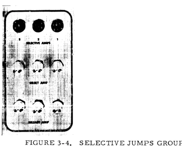
Manually Selective Jump . . . . 2-84 2-33
Conditional Jump Instructions . . . . 2-88 2-34
Index Jump . . . . 2-89 2-34
T hre shold Jump (not repe ated) . . . , . 2-90 2-35
Threshold Jump (repeated) . . . . 2-91 2-35
Equality Jump {not repe ated} . . . . 2-92 2-37
Equality Jump (repeated) . . . . 2-93 2-37
Q-Jump . . . . 2-94 2-39 Sign Jump . . . . 2-95 2-39 'Ze ro Jump . . . . 2-96 2-40
Scale Factor Instruction . . . . 2-107 2-43
Scale Factor . . . . 2-108 2-43 Stop Instructions . . . . 2-11 5 2-47
Manually Selective Stop . . . . 2-116 2-47
Program Stop . . . . 2-11 7 2-48
Input-Output Instructions . . . -... . 2-11 8 2-48
Print . . . . 2-119 2-48 Punch . . . . 2-120 2-49 Exte rna1 Function. , . . . . 2-121 2-49
E~te rna1 Read . . . . 2-122 2-50 Exte rna1 Write . . . . 2-123 2-50
PROGRAMMING (CONT.)
Floating Point Round Option . . . . Floating Point ... Add . . . . Floating Point Subtract . . . . Floating Point Multiply . . . . Floating Point Divide . . . . Floating Point Polynomial Multiply ... . F.ldating Point Inner Product . . . . Floating Point Normalize Pack . . . . Floating Point Unpac k . . . . Program Interrupt . . . .
SECTION III
OPERATION
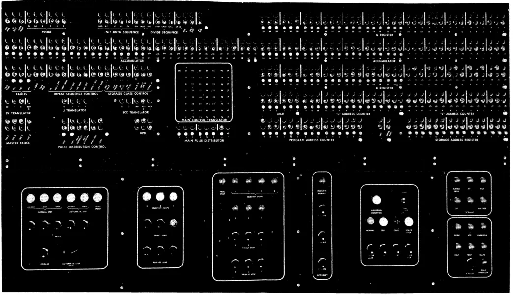
Supervisory Control Panel. . . . Operation of the Computer . . . . Gene ral . . . . Normal Mode of Operation . . . . Test Mode of Operation . . . .
Starting Operation . . . . Jump and Stop Selections . . . . Manual Interrupt Selection . . . • . Restoration of Operation after Stops . . . .
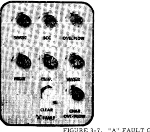
Programmed Stops . . . . Force Stop . . . . Emergency Stops . . . . Fault Stops . . . . Computer Faults . . . . General . . . . 't At' Faults . . . . Overflow Fault . . . . Divide Fault . . . . Characteristic Overflow Fault . . . . Print Fault . . . .
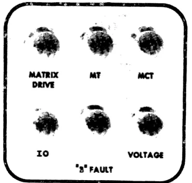
SCC Fault . . . . Temperature Fault . . . . Water Fault . . . . Abnormal Condition Fault . . . . "B't Fault . . . .
MCT. Fault . . . . Voltage and Matrix Drive Faults . . . . MT Fault . . . . 10 Fault . . . . Manual Re ading and Writing . . . .
Manual Writing from the Q Register . . . . .
Manual Reading to the Q Register ...
SECTION IV
INPUT-OUTPUT
Gene ral . . . '0' • • • • • • • • • • • • • • • • • • • • • • • • • Input-Output Sector lOA and lOB Registers. General . . . .; . . . . . The Input-Output Registers . . . . Input-Output Loc kout Circuits . . . . Inte rrupt Fe ature . . . . In-Out Fault Detection Circuits . . . . Exte rnal Instructions. . . . .. . .. . .. . Photoelectric Paper Tape Reader . . . . General . . . . Punched Paper Tape . . . . Photoelectric T ape Reader . . . . Tape Reader Modes of Operation . . . . PrograIT1IT1ing and TiIT1ing . . . . TiIT1ing . . . . SaIT1ple Seventh Level Loading Codes .. . Fault Detection . . . . Manual Preparation . . . . High Speed Punch . . . . General . . . . High Speed Punch . . . . High Speed Punch Register . . . . PrograIT1IT1ing and TiIT1ing . . . . Fault Detection . . . . Manual Preparation . . . . Electric Typewrite r . . . . General • . . . Electric Typewrite r . . . . Typewrite r Registe r . . . . PrograIT1IT1ing and TiIT1ing . . . . Fault Detection . . . . Manual Preparation . . . . Univac Card EquipIT1ent . . . . General . . . . Punched Cards . . . . Operating the Card EquipIT1ent . . . . Card 1'.1ovement . . . . Selections for Card Cycle Operations .. . PrograIT1IT1ing and TiIT1ing . . . . Sample Card Read Program . . . . Sample Card Punch PrograIT1 . . . . Sample Punch and Read Cards PrograIT1. Fault Detectioil . . . . Preparation for Operation . . . .
SECTION V
UNIVAC SCIENTIFIC MAGNETIC TAPE UNIT S
Gene ral . . . '.' . . . 0 0 • • • • • • • • • • • • • • • •
Unit ape . . . 0
Univac Scientific Uniservo
Tape Transport Mechanism . . . . Erase Head . . . 0 • • • • • • • • • •
Read -write Head . . . . Bad .Spot Detection . . . 0 • • • • • • • • • • •
Programmed Magnetic Tape Processing . . . . S election of a T ape Ope ration . . . 0 • • 0 •
Read Forward . . . 0 • • • • 0 0 0 • • •
Read Backward . . . ' . 0 ' • • • • • • • • • • • W rite Forward . . . 0 • • • • • 0 • • • • • • • • •
Stop . . . 0 • • • 0 • • • • • • • • • •
Move Forward .. 0 • • 0 0 • • • • • • • • • • 0 o • • 0 •
Move Backward. 0 • • • • • • • 0 • • • 0 • 0 0 • • • • •
Rewind . . . 0 • • • • • • • • • • • • • • • •
Rewind Inte r loc k . . . . Cnange Bias . . . 0 • • •
Selection of Variable Mode, or Continuous Data Input Mode, Operation . . . . Programming C onside rations . . . . Initiation of T ape Ope ration . . . . Fixed Block Length Mode Operation . . . . Format . . . . Programming and Timing . . . .
Read Forward Operation . . . . 0 • • • • • • • • • •
Timing . . . 0
Parity Error . . . 0 • • • • • • • • • • • •
Fault Conditions . . . 0 • • • • • • • • •
Sprocket Error . . . . lOB Read Fault . . . .
Read Backward Operation ... 0 • • • • • • • • • •
W rite Ope ration . . . 0 • • • • • •
Faults ... 0 • • • • • • • • • • • • • • • • • • • • • • • • • • •
No Information Fault . . . 0 • • • • • •
Too Few External Write Instructions .. Too Many. External Write Instructions .. Failure to Stop Tape after Writing .. .. Exceeding Timing Requirements . . . . Stop Tape Operation . . . . Move Forward Operation . . . .
Sprocket Error . . . '0
P AR • .t\G R.APH
UNIVAC SCIENTIFIC MAGNETIC TAPE UNITS PARAGRAPH PAGE
Move Backward . . . _.
5-108
5-24
Rewind . . . .5-111
5-24
Rewind Inte rloc k . . . .5-115
5-24
Change Bias Operation . . . .
5-118
5-24
Synopsis of Fixed Block Length Mode Operation
5-122
5-26
Available Computation Times . . . .
5-123
5-27
Fixed Bloc k Length Mode . . . .
5-124
5-27
Variable Block Length Mode Operation . . . .
5-132
5-31
Programming and Timing . . . .
5-138
5-32
Read Forward Operation . . . .
5-139
5-32
Errors During Reading . . . .
5-148
5-34
Parity Error . . . .
5-149
5-34
Mod 6 Error . . . .5-150
5-35
lOB Read Fault . . . .5-152
5-36
Other Faults . . . -. . . .5-153
5-36
Read Backward . . . .5-154
5-36
Write Operation . . . .5-156
5-37
Bad Spot Detection, Writing and Reading .. .
5-159
5-37
Errors During Writmg . . . .
5-165
5-38
Stop Tape Operation . . . .
5-169
5-39
l'vlove Forward Operation . . . .
5-1 72
5-39
Move Bac kward . . . .
5-1 76
5-40
Rewind, Rewind Inte rloc k, Change Bias . .
5-1 79
5-40
Synopsis of Variable Block-Length Mode
Oper-ation . . . .
5-181
5-40
Available Computation Times . . . .
5-182
5-43
Variable Block Length Mode . . . .
5-183
5-43
Continuous Data Input Mode Operation . . . .
5-192
5-45
Format . . . .
5-193
5-45
Block Control Code . . . .5-200
5-47
Programming . . . .5-206
5-49
Read Forward . . . .5-209
5-49
BCC Check . . . .5-211
5-49
Mod 6 Check . . . .5-213
5-50
End of Record . . . .5-215
5-50
lOB Read Fault . . . .5-215
5-50
Read Backward . . . .5-21 7
5-50
Stop Tape Operation . . . .5-220
5-50
Synopsis of Continuous Data Input Mode Oper-ation . . . .
5-223
5-51
Synopsis of Tape Operation Errors . . . .
5-224
5-52
Operation . . . .
5-226
5-56
Operation Indicators . . . .
5-227
5-56
Uniservo . . . .
5-229
5-56
Tape Control Cabinet . . . .
5-242
5-58
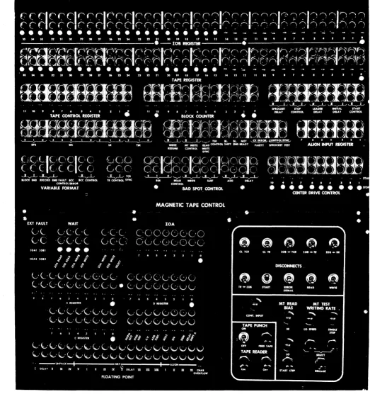
Supervisory Control Panel. . . .
5-246
5-59
Preparation for Operation . . . .
5-246
5-62
APPENDIX
Instruction Repertoire . . • . . . • . . . • . Powers of Two • . • • • . . . • • . • • . . . • • . Magnetic Drum Reserve Space Addresses •..• 10 B External Equipment S election Bits •••• . "
PAGE
A-I
A~5
se.ction
1
GENERAL DESCRIPTION·
. .Figure 1-1
1-1. GENERAL
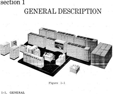
1-2. The Univac Scientific Computer model 1103A (see figure 1-1) is speci-fically' designed for applications requiring great programming versatility, high operating speed, and large storage capacity. Maximurn use of the high speed inherent in this computer is permitted by the unusual logical design and
its unique Program Interrupt feature. In addition to performing large scale
calculations, the system is adaptable to a wide variety of applications inclu-ding simulation and control in real time.
1-3 .. Programs of internally stored instructions, capable of self-modifica-tion, determine the sequence of operations. Thus, the computing system is
fully autom.atic. Its h.igh speed results from parallel mode operation whereby
1-4. DEFINITIONS.
1-5. Discussions of computer systems have led to the establishment of a
computer ulanguage. 11 Some of the more common term.s are defined in the
following parag_raphs.
The Univac Scientific utilizes binary notation in its expression of information. A binary digit is termed a bit. An array of binary digits is a word. Words are
held in the computer at storage locations or in computer registers.
A single-length Univac Scientific computer word consists of 36 bits. A Uni ... vac Scientific computer word may be an instruction, data with numerical
va-luet or data- coded in some arbitrary fashion.
A computer instruction consists of an operation code and operand references. The operation code describes to the computer what it is to accomplish. The operand references provide the data for the computer operation.
The Univac Scientific employs two-address logic. Each Univac Scientific in-struction has an operand code, a u-address portion, and a v-address portion. The u and v portions usually designate storage locations of operands for the instructions.
Each location which can be directly referenced in an instruction has an indi-vidual address. These locations constitute the addressable storage of the computer-. The addressable storage in the Univac Scientific is the Magnetic Core, the Magnetic Drum, and two registers in the computer (the
Accumula-tor and the Q Register).
Magnetic Core Storage provides storage locations for a total of 12t 2.88 words.
Of these, 4096 are standard with the computer, and the additional 8192 are
available optionally. Each of these storage locatiot;ls has an individual ad-dress.
The normally used storage capacity of the Magnetic Drum is 16, 384 words, each individually addressed. In addition to this storage space, the Magnetic Drum has amther 640 locations which are not normally addressable. The area of these locations is called the Reserve space on the drum.
Additional storage is provided by the Univac Scientific Magnetic T·ape System. Data stored on magnetic tape are accessible in blocks of a fixed or variable number of computer words.
1-6. BASIC PRINCIPLES.
1-7. Automatic operation of the computer proceeds under the direction of an internally stored sequence of instructions. Such a sequence of instructions is called a program. The main steps followed in producing a program are: (1) analysis of the problem, (2) flow-charting the problem, (3) coding the
1-8.
The coded p-rogram is convert-ed to a form which can be interpreted byext-ernal equipm:ent as input to the computer. The- input equipment places the program in the computer sto-rage under control of a "loading" program. Cer-tain- loading p:rogram.s may be permanently stored in the computer.
19. Once the program has been loaded into the computer, the computer is -then automatically set to_ execute the instruction s-tored at a fixed location. The location address of any instruction desired to be the first instruction to_ be executed can be manually inserted into the appropriate register on the com-puter control panel. When the comcom-puter is then started, the desired instruc-tion is extracted automatically from storage and placed in a co-ntrol register where it is held temporarily during its execution. Under automatic control, each instruction, from each next consecutive address, is extracted from
stor-age and executed. The procedure is continued until (1) an instruction is
en-countered which specifies the address of the next instruction to be executed,
or (Z) a program interrupt signal is received, or (3) a computer final stop is
effected.
1-10. The Program Interrupt feature of the Univac Scientific provides a
method of interrupting the execution of a program. A signal to interrupt a
program may originate in a unit of an external equipment, or it may be in ... itiated manually from the computer control panel. An. inte rrupt signal from exte rnal equipment indicate s- that the equipment is ready to receive output from the computer or is ready to send input to the computer.
1-11. Stored instructions, and instructions not inte rnally stored, may be ex-ecuted under manual control by following a particular procedure at the com-puter control panel. The comcom-puter may be stopped arbitrarily at the comcom-puter control panel during either automatic or manual operation.
1-12. The Univac Scientific handles many types of input and output equipment. Included as part of the basic computer system are an Electric Typewriter, a Photoelectric Paper Tape Reader, and a High Speed Paper Tape Punch. Equip-ments are available to handle on-line communication with punched cards and magnetic tape. Off-line communication between magnetic tape and a variety of Univac peripheral equipment is also possible. The Univac High- Speed Printer produces printed copy at the maximum rate of 600 lines per minute. Additional direct communication is possible with a variety of devices, such as a teletypewriter, an oscilloscope display unit, and analog-to--digital con-verters.
1-:-.13. C;:;ONTROL SECTION
. - - . _ _ ----IJ
X REG IS TE R
I~--~_~J
(36BITS)
L
IL-T---~----~--~-'r---~ __
---~--~I-r - ~-....,. - - - -
'~
___ -- -Ll ___
-'~_ ~
_____ '
---.---'1
I I
I
I I I
CONTROL
I
I
I
I I
L.. _ _ _ _ _ _ _ _ _ _ _ _ ~ _ _ _ _ _ _ _ _ _ _ _ _ ~ _ _ _ _ _ _ _ _ _ _ _ _ - _ _ _ _ ~
\1
Q
REGISTER
ACCUMU-(36
BITS)
LATOR
t (72 BITS>t
ARITHMETIC
"
INPUT OUTPUT
SECTION
PERIPHERAL
EQUIPMENT
~~--,~~~ ,~
~AGNETIJ ~AGNETI~
I
CORE
I I
DRUM
I
(4096-
(16 384
.12,288 t
WOR.
DS) tWORDS)
.
STORAGE
Figure 1- 2
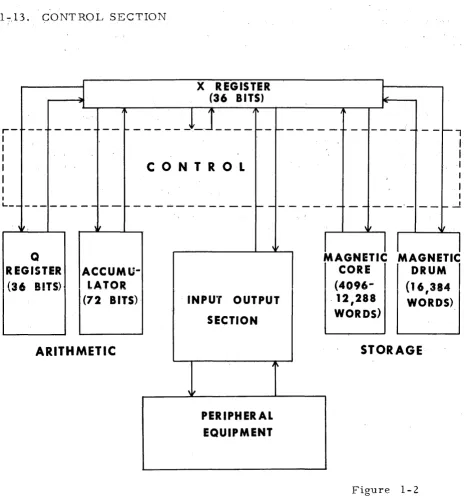
1-14. The Control Section of the Univac Scientific directs and regulates in-ternal operations of the computer, and in addition oversees data transmission of the compute r (see figure 1- 2). Control functions are de sc ribed in the
fol-lowing paragraphs (1-15 through 1-25).
1-15. The execution of an instruction has two phases: (1) the function of the
instruction is accomplished, and (2) the next instruction to be executed is de-termined and then placed in the Program Control Register (PCR). Each
in-struction to be executed is usually found in the Program Address Counter (PAK). Transmissions to or from storage of an instruction (or any computer word) are made according to the address held in the Storage Address Register
(SAR). A computer word is acquired (from the location specified by the
ad-dress in SAIl) and placed in the X Register. From the X Register; the com-puter word is directed to another position in the comcom-puter according to the current operation. For example, if the computer word in X is the next in-struction-to be executed, the content of the X Register is transmitted to the Program Control Register. The basic timing control for the above operations is provided by the Master Clock and the Ivlain Pulse Distributor.
1-16. MASTER CLOCK. Computer operations are synchronized by a central timing system called the Master Clock. The Master Clock propagates an electronic clock pulse every two microseconds, and controls the release of these clock pulses to the rest of the computer.
1-17. MAIN PULSE DISTRIBUTOR MPD. Certain pulses released by the Master Clock become Main Pulses. These pulses are denoted in the order of occurrence as Main Pulses zero, one, two, etc., through seven, MPO ... MP7. The number of Main Pulses initiated depends upon the instruction being exe-cuted.
Each Main Pulse controls certain functional sequences of subsidiary pulses. The actions effected by the subsidiary pulses are defined as occurring on the Main Pulse. On MP6 and MP7 the instruction to be executed next is brought from storage to the Program Control Register. On two or more of the pulses MPO through MP5, the function of the instruction in the Program Control Register is accomplished.
1-18. STORAGE ADDRESS REGISTER SAR. Each time a computer word
is to be placed in storage (written), or extracted from storage (read)', the ad-dress of this word is placed in the Storage Adad-dress Register. If writing is specified, the word in the X Register is recorded at the address held in SAR.
If reading is specified, the word at the address in SAR is extracted from storage and placed in the X Register. During shifting operations, the right-most seven bits of S AR are the shift count.
1-19. PROGRAM CONTROL REGISTER PCR. Each instruction is received from storage and held temporarily during its execution in the Program Con-trol Register. This register consists of a Main ConCon-trol Register MCR, of six bits; a U-Address Counter UAK, of 15 bits; and a V-Address Counter VAK, of 15 bits. These registers hold the v-address portion of the instruction.
oper-ation immediately. Indicoper-ation of the MCT fault is given on the computer con-trol panel. The structure of the Program Concon-trol Register is of concern when the Repeat instruction is used. (The Repeat instruction directs the computer to repeat the instruction at the next consecutive address a prescribed number of times.) The instruction to be repeated is acquired from storage only once. The instruction being repeated remains in the Program Control Register until the termination phase of the Repeat operation. The u and v addresses of the
repeated instruction are optionally advanced in U AK and V AK. Thus, the form of the instruction is altered in PCR, and not in storage.
1-21. According to the storage class, the advancement of addresses in UAK and VAK is as follows:
Magnetic Core Addresses
computer with one core bank
computer with two core banks
computer with three core bank,s
Q Register address
Accumulator addresses
Magnetic Drum addresses
advance from 00000 to 07777, return to 00000
advance from 00000 to 07777
to 10000 to 17777, return to 00000
advance from 00000 to 07777 to 10000 to 17777,
to 20000 to 27777, return to 00000
advance from 31000 to 31777, return.to 31000
advance from 32000 to 32777, return to 32000 advance from 33000 to 33777, return to 33000 advance from 34000 to 34777, return to 34000 advance from 35000 to 35777, return to 35000
advance f~om 36000 to 36777, return to 36000
advance from 37000 to 37777, return to 37000
advance from 40000 to 77777, return to 40000
1-22. The option of cycling within each core bank, if more than one is pro-vided, is also possible. This is usually done, however, only for maintenance and testing purposes.. By setting a SVITitch on the computer control panel, the
advancement of addresses in UAK and V AK is as follows:
from 00000 to 07777, return to 00000
}z
core banksbanks 3 core
from 10000 to 17777, return to 10000
froIn 20000 to 27777, return to 20000
sequen-tial execution of consecutive instructions, the termination phase of each of these instructions places the next consecutive instruction in the Program Con-trol Register. The following occurs on MP6: (I) the address in the Program
Address Counter is transmitted to the Storage Address Register. (2) The
con-tent of PAK is now advanced by one. (3) The computer word at the address
specified by SAR is transmitted to the X Register. Then, on MP7, the
con-tent of the X Register is transmitted to the Program Control Register.
According to the storage class, the automatic advancement of addresses in P AK is as follows:
discussion of the Program Control Re-gister. (The option of cycling within each core bank applies here also.)
Q Register Addresses advance from 31000 to 31777 to 32000, resulting
in an SCC fault
Accumulator Addresses results in an immediate SCC fault
Magnetic Drum Addresses advance from 40000 to 77777, return to 40000
Tlite Storage Class Control SCC computer fault occurs when an Accumulator address is specified as the address of the next instruction. Computer oper-ation is stopped immediately. The fault is detected when the address in SAR,
specifying the inst~uction to be read,is found to be an Accumulator address.
1-24. The address of the riext instruction to be executed, as taken from the Program Address Counter, is not always the address of the next consecutive instruction. Another address may be inserted in PAK during the execution of
the current instruction. Then, on MP6 and MP7, the instruction at this ad-dress is transmitted from storage to the Program Control Register. An oper-ation such as this effects a "jump. "
The address c;>f the next instruction to be executed is not always acquired from P AK. During the termination phase of a Repeat ope ration, a predete rmined address is inserted directly into the Storage Address Register !La "jump" was not effected during the Repeat ope'ration. Then, on MP6 and MP7, the instruction at the predetermined address is transmitted to PCR.
1-25. When computer operation is initially started, the Program Address Counter is automatically set to address 40000 and the Main Pulse Distributor
is set to MP6. Then, unless PAK and MPD are manually altered at the com~'
puter control panel, the first instruction is acquired from address 40000.
Address 40000 can thus be considered the starting address of a program if an
appropriate instruction is stored the re. 1-26. PRINCIPAL REGISTERS
1-27. The Accum.ulator, the Q Register, and the X Register are referred to
as arithmetic registers but serve several purposes. The AccuITIulator and the
Q Register can be referenced by the programmer since they are both
1-28. X REGISTER. _ The X Register is a 36-bit non-addressable register. As an exchange register, X temporarily holds words in their transmission from one computer location to another. As an arithmetic register, X l\olds the addend, subtrahend, multiplicand, and divisor in the corresponding arith-metic ope rations.
1-29. Q REGISTER. _ The Q Register' is a 36-bit register. As.an
arithme-tic register, Q holds the multiplier and the quotient in the corresponding
arith-metic operations, and the logical multiplier. As an_addressable storage
re-giste r, Q provides temporary storage. for a single .36~.bitw.or.d.. Any of the
addresses 31000 through 31777* may be used to reference the Q Register.
1-30. ACCUMULAT.OR. The Accumulator A is a 7Z-bit register (referred
to as a double- length register). The right"'!hand 36 bits of.the Accumulator is termed the content of AR; the left-most 36.bits.of the Accumulator is termed the.content of AL • As an arithm.etic register; the Accumulator.holds the sumt difference, product, and.dividend (and_final remainder) in the corresponding arithmetic. ope-rations. As an addressable storage register, the Accumulator
provides temporary storage for a 7i-!'bit word. AXJ.y of .the addresses 32000
through 37777* may be used to reference the Accumulator.
1-31. STORAGE
1-32. MAGNETIC CORE STORAGE, MCS.
*Note.
.Figure 1-3
The address of a storage focatl0n IS a lS-bit number, represented in
1-33. Magnetic Core Storage has the advantage of providing rninirnum acce s s tirne to stored information. We rds in core storage can be extracted or recor-ded in as few as eight "m.icroseconds. Each· bank of Magnetic Core Storage is capable of storing 4096 computer words. Up to three banks may be obtained with the cornputer. Each bank consists of a stack of 36 64x64 core rnatrices (see figure 1-3). At the intersection of each row and colurnn of a rnatrix is a core whichrnay be Inagnetized in a
"0"
or"I"
direction. A 36-bit cornputer word is stored by properly Inagnetizing a core in the saIne rnatrix position in each of the 36 rnatrices. This is illustrated in figure 1-4. The addresses assigned to the core locations are xOOOO through x7777, where x is 0, 1, or 2, depending upon the particular bank referenced.36 CORE MATRICES EACH BANK
LOCATION U
64
Figure 1-4 64
1-34. Since rnagnetic core storage provides rapid access storage, a prograrn which is ready for execution plus the associated data are usually located in core storage. The autoInatic acquisition of instructions frorn consecutive addresses in rnagnetic core storage proceeds froIn one core bank to another where rnore than one core bank is provided. This is continued until the exe-cution of the instruction at the last sto rage addre s s of the available magnetic core storage. Then, unless the last instruction specifies a jurnp, the next instruction to be executed is acquired from. the first address of core storage. The sequential procession is then resumed with instructions being obtained frorn consecutive addresses in the first core bank.
1-35. MAGNETIC DRUM STORAGE MD.
1-36. The access time for words in Magnetic Drum Storage is slower than the access time for words in Magnetic Core Storage. The Magnetic Drum is valuable for the storage of "blocks" of instructions (or data) which are to be transferred to core storage prior to their execution (or processing). A trans-fer rate of 31J 250 words per second is possible between the drum and core storage.
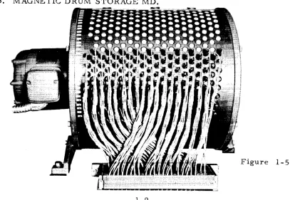
1-37. DESCRIPTION. The Magnetic Drum (see figure 1-5) contains a conti-nuously rotating cylinder surfaced with a material that can be magnetized lo-cally. Information is stored as magnetized spots on specific areas of the drum through recording heads attached around the outside of the drum case. The
storage areas normally used provide addressable storage for a total of 16,384
36-bit computer words. A word can be extracted from or recorded at a given
location only once during a drum revolution. This results in a maximum ac-cess time of 34 millisecondsJ the time consumed by a complete drum revolu-tion. The most efficient use of drum storage is achieved by storing words at locations which are in position for reading or writing at the time the locations are referenced (this procedure is called minimum access coding. )
1-38. The addresses of the drum locations are divided into four groups, each of which has 4096 normally used locations addressable as xOOOO through x7777, where x is 4, 5, 6, or 7. The sequential acquisition of instructions continue s from 40000 . . . 47777 to 50000 . . . 57777 to 60000 . . . etc ... 77777 to 40000 ...
1-39. VARIABLE INTERLACE SYSTElvL Each addressable storage location on the drum is "marked" according to a recorded timing track. An index po-sition is recorded on a separate track. As the drum revolves, an Angular
Index Counter, AIK, is advanced by the recorded timing track. As each drum
location is in position for reading or writing, its address is momentarily in the Angular Index Counter. The Angular Index Counter is advanced from the index position through 4095 positions, or from xOOOO to x7777, after which AIK is cleared to zero. These are the addresses of the normal drum storage locations. The advancement of AIK is resumed then from zero forward until the index position is reached, at which time AIK is again cleared. The ad-tUresses in AIK during this advancement are the addresses of the reserve space locations.
The time which elapses between the positioning of adjacent drum locations for reading or writing is approximately eight microseconds. Consecutive reading and/ or writing in adjacent drurn locations cannot be COIYlpleted in this short a
time. For example, if adjacent drum locations are chosen for successive
reading or writing, a complete drum revolution would occur before the second
read or write could be accomplished. A variable interlace system, which
the proper positioning of consecutively addressed drum locations. This allows the computer a maximum of 32 microseconds to complete one drum reference. Figure 1-6 illustrates the selection of drum locations with a four interlace (the layout of locations as illustrated does not comply strictly ,vith the actual arrangem.ent on the drum.). The interlace is manually selected and is indica-ted by a light on the computer control panel. Interlaces 4, 8, 16, 32, and 64 are available.
GROUP 4 GROUP 5 GROUP 6 GROUP 7
4000~CcATI)\ ~~~I?\
,.,\.\
"\~""""'\
\
( . . . .
'.':
\
ADDRESS
ADDRESS (ADDRESS
40001 = LOCATION 40004
( I
42000 : LOCATION) 40001
I I
DIRECTION
OF
ROTATION
L _ _ _ _ _ _ _ _ _ _ _ _ _ _ _ _ _ _ _ _ _ _ _ _ _ _ _ _ ..1
Figure 1-6
1-40. A coded address reference is converted to an "interlaced" address as shown in figure 1-7. This illustrates the conversion for a four interlace.
DRUM GROUP SPECIFICATION
~
214213212 21121029
[ [ I
X X XFigure 1 ... -, 7
COOED ADDRESS
( INTERLACED
( ADDRESS
The connection lines for each interlace are from position 2° to position (2 0 xZm), from position 2. 1 to position (2. 1x2.m), etc., where Zm equals the interlace expressed as a power of two.
1~41. A check is made for coincidence between the interlaced address and the
address momentarily in the Angular Index Counter, and when coincidence occurs,
a read or write operation occur·s. During "Normal drum" operation, coinci-dence checks occur only when the Angular Index Counter is advancing through the normal drum locations (addresses xOOOO through x7777).1-42. RE SERVE SPACE. Each drum group, in addition to the previously mentioned 4096 addressable locations, has other locations which are not nor-mally addres·sable. The area of these locations is called the Reserve space. The area shown in figure 1-6 is between locations 47777 and 40000. 57777 and 50000, etc. Communication is established with these locations and broken with the rest of the drum by setting the NORMAL/ ABNORMAL DRUM switch on the computer control panel to its abnormal setting. During the" Abnormal drum" operation, coincidence checks occur only when the Angular Index
Coun-ter is advancing through the Reserve space locations,
a
and forward, up to theindex position. If an interlaced address is greater than the number of locations
in the Reserve space, coincidence will.not be achieved. A program can safely reference for reading no more than the known minimum of Reserve space lo-cations. The practical known minimum is 160 per g:roup, octal addresses 0000
through 0237, for each drum group 4, 5, 6, or 7. If more than this number
of locations are known to be available, they can of course be referenced.
l-43. According to the interlace, the following number of drum. locations can be referenced for each group during each drum revolution. This assumes that a total of 160 locations are available per drum group. The addresses which are coded to reference reserve space locations are listed in the appendix.
With a four interlace - 40 locations (for each of 4 revolutions) With an eight interlace .. 20 locations (for each of 8 revolutions) With a 16 interlace - 10 locations (for each of 16 revolutions) With a 32 interlace - 5 locations (for each of 32 revolutions) With a 64 interlace - 3 locations for each of 32 revolutions and
2 locations for each of remaining 32 revolutions
The matter of addressing the reserve space on the drum should not ordinarily concern a programmer, since writing on the reserve space is accomplished only by maintenance procedures. The interlace and storage locations of rou-tines stored on the reserve space are fixed and kno\vn for future reading after
this initial writing. Normal usage of the res~rve space is for safe storage of
routines needed to load programs into the computer. Once transcribed on the drum, the se routine s are always available sine e it is not po s sible to de stroy them by writing ove r them.
1-44. ADDRESSABLE STORAGE.
Addresses --in Octal Notation Class
00000-07777 MCS-O 4096 36-bit words
10000-17777 MCS-l 4096 36-bit words (optional)
20000-27777 MCS-2 4096 36-bit words (optional)
31000-31777 Q Register 1 36-bit word
32000-37777 Accumulator 1 72·-bit word
40000-77777 MD 16,384 36-bit words
1-46. Several locations i~ storage are automatically referenced during
com-puter operation. Because of this fact, these locations are usually reserved by the programmer. The addresses of these locations are termed fixed ad-dresses and are as follows.
fixed addre s s F 0 fixed address F1 fixed address F2 fixed addre s s F3 fixed addre s s F 4
the location addressed as 40000
the location addressed as 00000 or 40001 the location addressed as 00001
the location addressed as 00002 the location addressed as 00003
Fixed address F1 may be assigned to the drum location addressed ·as 40001 by a manual selection on the computer control panel. The use of" some of these addresses by certain of the computer instructions is pointed out in the section Instruction Repertoire.
1-47. The addresses listed subsequently are considered illegal under the cir-cumstances noted. If reference to these locations is made, a computer fault occurs which immediately stops computer operation. The fault is indicated on the computer control panel as an SCC (Storage Class Control) computer fault.
30000-30777
10000-17777 20000-27777.·
32000-37777
31000-31777 32000-37777
Unassigned addresses
MCS-1 MCS-2
A
Q A
Illegal under all circumstances
Illegal if these banks of core storage are not provided
Illegal if any of the se addre s se s are specified as the address of the next instruction.
40000-77777
MD
1-48. MAGNETIC T APE STORAGE.
Illegal if an External Read instruction tries to place data (from external e.quipment) in drum storage; or if an External Write instruction tries to ex-tract data (for external presentation) from drum storage.
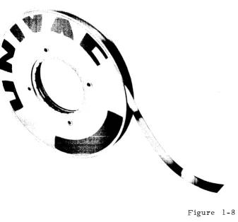
Additional storage for the computer is provided by the use of the Magnetic Tape System. A complete discussion of the tape system can be found in the section describing input and output equipment. The Magnetic Tape System comprises a number of tape transporting devices known as Uniservos, and a control section which is located in the computer structure. This system pro-vide s for the transfe r of information between the compute r and a removable reel of tape on a Uniservo. A maximum of 10 functional Uniservos can be used with the tape system. Information is transferred (read from the tape or written on the tape) under program control. A reel of magnetic tape is shown in figure 1-8. Any reel of tape 1500 feet or less is acceptable for use on the Uniservos.
1-49. Information is recorded as magnetized areas in a "line" across the width of a tape. Six data bits are recorded in each line along with a check bit and a timing bit. Lines are recorded at a density of 128 or 50 per inch.
1-50. Information is recorded in one of three formats. These are Fixed Block Length Recording, V'ariable Block Length Recording, and Continuous Data Input Recording. The modes of operation for recording in either the Va-riable Block Length or Continuous Data Input are optional with the tape system.
1-51. In the Fixed Block Length Recording mode, information is recorded in block lengths of 120 computer words (720 lines). A blockette consists of 20 computer words (120 lines). Either of two unrecorded space's exist between blocks. The space between blockettes, if a space is desired, also can be either of two lengths. The block and blockette spacing are chosen according to the use to be made of the information. Off-line processing of data is possible by using the recorded reel of tape on a variety of Univac peripheral equipments. Infor-mation can be both recorded and read in fixed block lengths. Based on a space of one inch between blocks of fixed length, and no space between blockette s,
a maximum of approximately 326t 000 computer words can be stored on a 1500
foot reel of tape. The maximum transfer rate of information between the com-puter and the tapes is approximately 1800 comcom-puter words per second.
1-52. In the Variable Block Length Recording mode, information is recorded with a variable number of words in a block. Blocks of information are sep-arated by unrecorded areas on the tape. Information can be recorded and read in variable block lengths at a maximum transfer rate of approximately 2100 computer words per second.
1-53. The Continuous Data Input mode reads information which has been re-corded continuously on the tape. There is no "block" limitation except for the length of the tape. This form of recording is useful for real time observations which will not permit interruptions to format the information in fixed or vari-able block lengths.
1-54 STATED POINT COMPUTER ARITHMETIC
1-55 NUMBER NOTATION.
A quantity in the Univac Scientific carries a positive or negative value conno-tation according to its represenconno-tation in one I s complement notation. The
left-most bit of the quantity in one I s complement notation is indicative of the sign
of the number represented. If the number represented is positive, the sign bit is zero. If the number represented is negative, the sign bit is one. A number negative in value appears in the computer as the one I s complement of
its absolute value. Thus, each zero in the representation of the absolute value becomes a one, and each one becomes a zero. For example, the representa-tion of decimal (t-13) as a computer word is
Since this is also the representation of the absolute value of decimal (-13), the representation of decimal (-13) is the one's complement of this, or
III III III III III III III III III III 110 010~~
Any bits between the sign bit and the most significant bit of the number repre-sented are also indicative of the sign of the number. Thus, the most signifi-cant bit of a quantity is the first bit to the right of the sign bit which differs from the sign bit. In the example above, note that each bit to the left of the most significant bit appears the same as the sign bit. This is less obvious when a number is represented in octal notation. The octal representation of decimal (+13) is 000000000015. The octal representation of decimal (-13) is 777777777762.
1-56. In stated point arithmetic operations, the natural arithmetic of the com-puter, the machine treats all quantities as integers. However, the integral capacity of the registers does not limit arithmetic operations to dealing only with numbers in this integral range. Number,s outside the integral capacity of a 36-bit register ITlay be handled by programming appropriate binary scal-ing or by use of the instructions in the optional floatscal-ing point arithmetic pack-age. The latter provides autoITlatic treatITlent of 36-bit signed quantities of the forIn, x~
zy.
1-57. The quantity zero has a positive and a negative representation in the computer, naITlely, in octal notation, 000000000000 or 777777777777. However, it is not pos sible for the representation of "negative" zero, 777777777777, to be generated as the result of an arithITletic operation. A "negative" zero, generated in SOITle other way, is treated as the quantity zero in arithmetic operations.
1-58. In an n-bit register, no ITlore than n-l bits can represent the value of a signed integer since at least one bit represents the sign. Thus, the range of signed integers which can be represented in an n-bit register is -(2n -l -l)to +(zn-tl). Hence, the positive integers which can be represented in a 36-bit register lie in the range 1 to 2 35_1, or as expressed in octal notation,
000000-000001 through 377777777777. The negative integers which can appear in a
36-bit register lie in the range -1 to _(2 35 _1), or as expressed in octal
nota-tion, 777777777776 through 400000000000,
The range of nUITlbers possible to represent in a 36-bit register can be illus-trated as follows:
DECIMAL BINARY
34, 359, 738, 367 ::: (2 35 -1) a 11
III III III III
1111 1 1 III
111III III III
34,359,738,366 ::: (2 35 _2) 011 III Iii iIi Iii iii iiI III III III III 110
.
.
9 ::: (2 3+ 1) 000 OQO 000 000 000 000 000 000 000 000 001 001
8::: 2 3 000 000 000 000 000 000 000 000 000 000 001 000
7 ::: (2 3 -1) 000 000 000 000 000 000 000 000 000 000 000 111 6 ::: (2 3 -2) 000 000 000 000 000 000 000 000 000 000 000 110
... I ... ~_,
000 000 000 000 000 000 000 000 000 000 000 101
::> ::: \,,--jl
4 ::: 22 000 000 000 000 000 000 000 000 000 000 000 100
3 ::: (22_1) 000 000 000 000 000 000 000 000 000 000 000 all
2::: 21 GOO 000 000 000 000 000 000 000 000 000 000 010
1 ::: 2° 000 000 000 000 000 000 000 000 000 000 000 001
a :::
000 000 000 000 000 000 000 000 000 000 000 0000
III
111
III
111III
111III III III III III
110-1 ::: - 2
- 2 ::: ~ 21
III III III III III III III III III
1.11III
101 -3 ::: -(22_1)III III III III III III III III III III III
100-34,359,738,366=-(2 35 _2) 100 000 000 000 000 000 000 000 000 000 000 001 -34,359,738,367=-(2 35 _1) 100 000 000 000 000 000 000 000 000 000 000 000
1-59. Basically, arithmetic operations involve the acquisition of operands from storage, the manipulation of these operands in the X Register, Q Register, and/or the Accumulator, and the storage (usually) of the derived results. Whet). any 36-bit register, addressed as u, has its content, (u), transmitted to the 72-bit Accumulator, 36 additional bits are assumed to the left of the left-most sign bit of (u). This 72-bit word is termed a double-length extension of (u). The extended word is denoted as D(u) if the 36 bits to the left of the sign bit are the same as the sign bit. The 72-bit word D(u) retains in all cases the same numerical value as the 36-bit word (u). The extended word is denoted as a Split extension, S(u), if the 36 bits to the left of the left-most sign bit are all zeros. The value of the sign bit of (u) is disregarded for the Split exten-sions. Thus, for positive numbers only, S(u) has the value of (u) and D(u).
The following examples illustrate double-length extensions.
if (u) ::: 000 000 000 000 000 000 000 000 000 000 000 101:::
decimal (+5) *D(u) ::: 000 000 ••• 000 000 000 000 000 000 000 000 000 000 000 000 101:::
decimal (+5) S(u) ::: 000 000 •.• 000 000 000 000 000 000 000 000 000 000 000 000 101:::
decimal (+5)
if (u) = I I I
111
I I I I I I 111 111 I I I 111 111 111 111 010 = decimal (- 5)D(u) = I I I 111. •• 111 I I I 111 I I I I I I I I I 111 I I I 111 III III 111 010 = decimal (- 5)
S(u) = 000 000 ••• 000 I I I I I I 111 111 111 111 111 111 111 111 111 010 = decimal (2 36 _ 6)
Split extensions are useful in multiple preci.sion arithmetic where a single number may be stored in n registers. In this case, the ,digit in the sign bit position may be used to represent a si~nificant bit in n-l of the n registers.
1- 60. SHIFTING.
1- 61. The Accumulator and the Q Register both have left circular, or end-around, shifting facilities. Bits shifted off the left end of these regis~ers ap-pear in order in the right-hand side. Multiplication of a number by 2 is, accomplished by shifting the numbj[ left k places. Note: a shift cannot be considered as a multiplication by 2 if the most signIficant digit of the number is shifted into (or through and end-around) the sign bit position. Such a shift of the most significant bit of a number into the sign-bit position of a register changes the value attached to the number from positive to negative, or from negative to positive.
The following examples illustrate shifting, in the Q Register, a number from register u.
(u) = 000 000 000 000 000 000 000 000 000 000 000 101 = decimal (+5)
initial content of Q.
(Q) 0= 000 000 000 000 000 000 000 000 000 000 000 101 =( 22+1) I
o ( ) • 32 ( 2 ) 32 34 32
after a left shIft of 32 places, Q i 2 = . . . = 2 +1 2 =2 +2
(Q) =
a
1a
100 000 000 000 000 000 000 000 000 000 000 = 2 34 +2 32o ( ) o . 33 ( 2 1) 33 35 33
after a left shIft of 33 places, Q 1 2 = . . . , . . . = 2 3+:tt 2 3 =2 +2
(Q) = 101 000 000 000 000 000 000 000 000 000 000 000 =-(2 +2 3_1)
. . 34 2 34 36 34
after a left ShIft of 34 places, (Qh 2 = . . . , . . . =(2 +1) 2 =2 +2
(Q) =
a
1a
000 000 000 000 000 000 000 000 000 000 00 1 = 2 34 +1(u) 111 111 I I I 111 111 I I I 111 I I I I I I 111 111 010 = decimal (-5)
initial content of Q.
(Q) i= I I I I I I I I I 111 I I I I I I I I I 111 I I I I I I I I I 0 1 0
= -
(22 +1)after a left shift of 32 places, (Q)(232
= . . .
=-(5!l)z3~~-(;i34+z3~
( Q) = 1
a
1a
1 1 11 1 11 1 1 11 1 1 1 11 1 111 1 11 1 11 11 1 111 = - ('" + z3 )after a left shift of 33 places, (Q) 0,2 33 = • . . • . . • • . .
=-(z2+1)z33=_(z35+z3~
after a left shift of 34 places, (Q) .• 2 34 =. . • . . . . • •
=-(z2+l)23~_(z36+z3~
(Q)
=
1 0 1 III III III III III tIl III III III III 11 0=
(234 +1)The instructions which order left shifts in the .. A ... ccurnulator or Q Register allow the programmer to designate a shift count k in the range 2 7
>
k~
o.
A left shift of k piaces is eqUivalent to a right circular shift of 36-k places in Q or 72-k places in A.1-62. ADDITION AND SUBTRACTION.
1-63. For the computer process of addition or subtraction, the addend or subtrahend is placed in the X Register. Then, if a subtraction is desired, either D(X) or S (X) is subtracted from the content of the Accumulator. If an addition is desired, the complement of D(X) or S(X) is subtracted from the con-tent of the Accumulator. The subtractive and end- around borrow properties of the Accumulator eliminate the possibility of the generation of a negative zero representation during arithmetic operations. The subtraction process necessitiates an ability of the machine to perform an end-around borrow in the Accumulator, i. e., apply a borrow propagated past the bit A7l to the bit
AO.
This process is illustrated in the following example, in which a 72-bit Accumulator and a 36-bit X Register are used.initial content of A,
(A). = 000 000... 000 000 000 0 00 000 000 000 000 000 000 000 11 0 = ( +6) 1
minus
D (X)
=
0 0 0 0 0 O. • • 000 000 (HHlv v v nnn vvv 000 000 ( \ ( \ ( \ uuu 000 000 000 000 III
= - (
+7) 111 111 •.• 111 III III III III III III III III III III IIIend- around borrow of 1
( A) f
=
III 1 11.. . III III 11 1 III 1 11 III 1 1 1 1 11 1 11 1 11 1 1 1 11 0= -(
+1)= final content of A
Essentially the Accumulator subtracts modulo (2 71_1). For example, if the value of one is added to the largest positive number possible in the Accumula-tor, the result is the machine representation of the largest possible negative number in A. Care must be exercised in the accumulation of sums in order that neither the positive nor negative capacity of the Accumulator is exceeded.
1-64. MULTIPLICATION.
1-65. For the computer process of multiplication, the multiplier is placed in the Q Register and the multiplicand is placed in the X Register. The
multipli-cation process forms the product in the Accumulator. The product is formed
Accumulator and a 36-bit X Register and Q Register, is illustrated in the fol-lowing example.
D(X)= 000 000 .•• 000 010 000000 OQO 000 OM 000 000 000 000,-<)00 '000=2 34
(Q)= 000 000 O-Ot) 000 000 000 000 000 000 000 001
a
I 0-.i3+2l(A)= 000 000 ••• 010 100 000 000 000 GOO 000 000
000
000 000 000OO(;)~7+235
=
productImminent overflow is detected during an accumulative multiplication process. A check is made to determine if the addition of a product to the content of the Accumulator might cause an overflow of the sum into A 7 1' If this possibility exists, the accumulative multiplication operation is restrained by a stop of computer operation. An Overflow computer fault is iHdicated on the computer control panel.
1-66. DIVISION
1-67. For the computer process of division, the divisor is placed in the X Reg-ister and the dividend is assumed to be in the Accumulator. The regReg-isters are employed in such a manner that
(A) i
=
(X) • ( Q)+
R, whereO~
R<I
(X)I
The content of the Accum.ulator befor~ the division is denoted by (A) i. Tl1e
re-mainder, or the final content of A, is denoted by R. The remainder left in
the Accumulator by the division process is always non-negative. The place-ment of the dividend in the double-length Accumulator allows the formation of
a quotient with the maximum of 35 significant bits (and a single sign bit) . This
is true regardless of the value of the divisor in the X Register. The magnitude
allowable for the quotient is limited only by the capacity of the Q Register.
The following examples illustrate some of the facets of the division process.
Case I - dividend and divisor both positive
dividend (A) i
=
000 000 ••• 010 100 000 000 000 000 000 000 000 000 000 000 100=
(z3
7+z3
5+z2)divisor (X)
=
000 000 000 000 000 000 000 000 000 000 00 I 010= (2 3 +21)derived quotient (Q)
=
01 0 000 000 000 00 0 000 000 0 00 000 000 000 000 = ( 2 34)
remainder, final content of A, =
000 0 00. • • 000 000 000 000 000 000 000 000 000 000 000 000 100 = ( 22)
dividend (A)"
=
III Ill •••
i
0 1 0 11 III III III III 111 III III III III 111 0 II=,-( 237+z3
5+z2)
divisor (X) = i 11 III III III 111 111 III III III 111 11 0 1 0 1=-( 23+21)
derived quotient (Q)
=
010000 000 000 000 000 000 000 000 000 000 001 = (234+2 0)
remainder, final content of A
=
000 000 ••• 000 000 000 000 000 000 000 000 000 000 000 000 110= (2 3_22+21)
Case III - positive dividend and negative divisor
dividend (A. ) 0"
=
000 000. •• 10 100000 000 000 000 000 000 000 000 000 000 100=
(~7+z.35+t)
divisor (X)
=
III III III III III III III III 111 III 11 0 1 0 1=-( 23+21)derived quotient (Q)
=
1 0 1 11 1 III 11 1 11 1 1 11 III 111 III 11 1 III III = _ (2 34)
remainder, final content of A, ::: 2
000 000 ••• 000 000 000 000 000 000 000 000 000 000 000 000 100= (2 )
Case IV - negative dividend and positive divisor
dividend (A)" _ _ _ _ _ 1 =
III Ill •••
ro
1~... ~...
..,
011111 III III III 111 11-1 III III III III 011
=_(2"'/ ... 2"'J+i'")
divisor (X)
=
000 000 000 000 000 000 000 000 000 000 001 010= (23+21)derived quotient (Q)
=
1 0 1 111 111 III III 111 111 III 111 III 111 11 0 = .... ( 234 +2 0)
remainder, final content of A, =
000 000 ••• 000 000 000 000 000 000 000 000 000 000 000 000 110 = (2 3 - 22+21) It is possible that the quotient that sh,ould be derived would exceed the capacity of the Q Register. If the conditions pointing to this fact are detected during the division process, computer operation is stopped immediately, and a Divide fault is indicated on the computer control panel.
1-68. SCALING.
1- 69. The Univac Scientific treats all quantities as integers when ~~ndling, them in arithmetic operations. Numbers not lying in the range 1- 2
~&~
z;>5_ l (for single precision operations) can be expressed as s =S!,
2S
2 where sl is aninteger within the above range. Thus the machine representation sm of a
quantity s is actually the quantity times some power of two or the qu"antity "scaled" the number of places specified by the power, The term 2S2 is called the scale factor; the term S2 is the "scaling. "
For example, one representation of the fraction 1
{2
in the form s =as follows~
s
=
1/2'= 2 -1 = O. 1 in binary notationIn the form s = sl • 2S2• -1
0.1=1.0(2 )
s · 1
The machine representation 1. 0 is the quantity 0.1 times 21, or the quantity 0.1 scaled one place.
1-70. Two quantities sm and t can be added, subtracted, multiplied, or
di-vided. However. if these quan'Yfties are scaled representations of sand t, the scaled representation of the result may not have the same scaling as that of
the operands. The programmer must keep a record of the scaling of all
operands and all results.
1-71. Also, the results may have to be adjusted, or re- scaled, if it is desired that the machine representations do not exceed the capacity of a 36-bit location.
Consider the multiplication of two quantities sand t represented in the form
s = s1 • 2S2 (and t = tl • 2t2). The scale factor 2S2
is assigned a value, de-pendIng upon the range of s, such that sl does not exceed 2 35 _1 (for a single precision operation). Thus, the quantity s is scaled so that its machine repre= sentation s does not exceed the capacity of a 36-bit location. The multiplica-tion of the machine representamultiplica-tions of sand t yields the result rm = sm' t m • In terzns of the quantities sand t, the result is in the form s· t = ~= \ sl'
tIl-2S2 +t. The machine -representation r is the result r scaled -( s2
+
t
2).
How-ever, if the quantity rm is to be
stpred~t
a 36-bit location, its m.agnitude must be checked since it may exceed the capacity of a 36-bit location.For example, consider the mult~plication of two binary quantities
s = O. 1
and t =
0.1
=
2 -1+ •••
= 2- 1
+
...
If twenty significant bits are desired for the machine representation of each number, these numbers, represented in the form s = sl · 2s2, are
(0.1 .•• ) = (2-1
+ ... )
= (219+ •••
)2+20 The machine representations s a n d t a r em m
000 000 000 000 000 01.
000 000 000 000 000 01.
...
However, the result is in the form
19 19 -40
r=(2 + ••• ) (2 + •.• )2
where the product is scaled
18
places sUf~ that the machine representation of the product is in the range 2>
r2
2 . In this case the pr~ct must bescaled down so that its machine reP'1-esentation is in the range 2
>
r2
233 , This is accomplished by a "right shift" of five places which insuresth~
the most significant bit of rm is in A34 or A33. Now the result is in the form
r =[ (219 + ... ) (219 + '.' • ) 2 - 5 J2 - 40 . 2 +5
where the machine representation of the result r . m
Oxy . .• •.• ••. ••. .•• ..• ••• .•• .•• .•. • .• = (2 +".) (2 19 19 +, .• )2 -5
is the product scaled 35 places. In this example, either bit x in A34 or bit y in A33 is a one.
1-72. An example of the above multiplication using specific quantities is as follows.
In the form s
s = 0.100 t = O. 110
s2
=
sl · 2 •...,. -1 = \'? 19\/ ? - 20
U.IUU
=
~ w w0.110 = 2-1 + 2-2 = (219 + 218 )2-20
The machine representations s a n d t a r e
m m
000 000 000 000 000
a
1a
000 000 000 000 000 000 = 000 000 000 000 000. all 000 000 000 000 000 000 =The product r of the quantities sand t is O. all 000. the form
However, the result is in
where the product is scaled 40 places such that the machine representation of the product in the Accumulator is
000 000, , .110 000 000 000 000 000 000 000 000 000 000 000 000=
(23
8+2 37)where the machine representation of the result r •
- m"
011 000 000 000 000 000 000 000 000 000 000 000
is the product scaled 36 places,
1-73. If the maximum number of significant bits are to be retained in the right half of the Accumulator, the most significant bit of the result must be found in A
34, A quantity n which is scaled to its maximum representation in a 36-bit location, such that n is in the range of 235
>
n.2
2 34 , is said to be normalized. The quantity+
9.000 000 000 000 000 000 000 000 000 000 001 001
in its normalized form is
.0 1
a
010 000 000 000 000 000 000 000 000 000 000The quantity above, expressed in octal notation is 000000000011; this quantity in its normalized form is 220000000000.
1=74. LOGIC.A.L OPER .. ~~TIONS.
1-75. Ce rtain of the compute r operations can be used for the formation of logical sums, logical products, and an "exclusive or" combination of compu-ter words.
The "exclusive or" combination of binary digits is illustrated to the right. The "exclusive or" is one when either, and not both, of the binary digits is one. The "exclusive or" combination of two compu-ter words x and y is found by adding each bit of x to the corresponding bit of y and disregarding any carry. The notation for this process is x(f)y. A computer word formed by the "exclusive or" pro-cess is shown below.
0 1 0 1
Q.Q.ll
o
1 1 0x
=
000 101 110 000 100 010 000all
110 010 100all
y
=
all
000 100 110 101 000 III III 001 101 100.101x®y
=
all
101 010 110 001 010 III 100 III III 000 110The logical sum of two binary digits is illustrated to the right. The logical sum, "inclusive or", is one when eithe r, or both, of the binary digits is one. The logical sum of two computer words x and y is formed by placing a one in each bit position where either or both x or y has a. one in the -correspond-ing position. A logical sum is illustrated below.
0 1 0 1
Q.Q.ll
x=
y
=
000 101 110 000 100 010 000
all
110 010 100all
all
000 100 110 101 000III III
001 101 100 101logical sum
=
all
101 110 110 101 010III III III III
100III
The logical product of two binary digits is illus-trated to the right. The logical product, "con-junction", is one when, and only when, both of the binary digits are one. The logical product of two computer words x and y is found by multiplying
o"=,,..h 'h.;+ ... .f 'V" 'h. ... +'hQo ,.."' __ ,.,. .... "" ... ,.J~ .... _ l-..~+ ~&.. !"T'1...._
... ...., ... ~ JJ] ... \;.. ~\J ... ~;:,pv ... u"" ... ~ U,,"l. U.1. y. .1.1.1.'== notation for a logical product is x@y. A logical product is illustrated below.
a
1 0 1Q.Q.ll
a a a 1
x
=
000 101 110 000 100 010 000all
110 010 100all
y
=
all
000 100 110 101 000III III
001 101 100 101x@y
=
000 000 100 000 100 000 000all
000 000 100 0011-76. FLOATING POINT NUMBERS IN THE COMPUTER
1-77. A quantity expressed as a floating point number is in the form X· 2Y.
The quantity x is te rmed the mantis sa. The quantity y is te rmed the
char-acteristic. If the mantissa and characteristic are stored in individual
regis-ters, the flo~ting point representation is said to be unpacked. If the
man-tissa and characteristic are stored in the same register, the floating point representation is said to be packed. The Univac Scientific uses a packed
re-pre sentation.
1-78. In the Univac Scientific floating point system, certain restrictions are placed on the range allowable to the quantities x and y. The mantissa x is
restricted to a normalized representation such that ~< x
<
1 (for non-zeronumbers). The characteristic y is restricted to -128~<128.
1-79 .. The characte ristic y is biased for its repre sentation in the compute r such that the biased characteristic is always positive. The biased
character-istic is y + 128 such that O~y + 128<256. The bits u34 ... u27 are the biased
characteristic of a floating point number packed in register u.
1-80. The mantissa x is represented in one's complement notation by a sign bit and 27 bits of significance. The bits u26 ... uo are the significant bits of the mantissa of a floating point number packed in register u. The :most sig-nificant bit of the normaliz