Manual
Software Version 1.14xx
MSLC-2
WARNING
Read this entire manual and all other publications pertaining to the work to be performed before instal-ling, operating, or servicing this equipment. Practice all plant and safety instructions and precautions. Failure to follow instructions can cause personal injury and/or property damage.
The engine, turbine, or other type of prime mover should be equipped with an overspeed (overtempera-ture, or overpressure, where applicable) shutdown device(s), that operates totally independently of the prime mover control device(s) to protect against runaway or damage to the engine, turbine, or other type of prime mover with possible personal injury or loss of life should the mechanical-hydraulic gov-ernor(s) or electric control(s), the actuator(s), fuel control(s), the driving mechanism(s), the linkage(s), or the controlled device(s) fail.
Any unauthorized modifications to or use of this equipment outside its specified mechanical, electrical, or other operating limits may cause personal injury and/or property damage, including damage to the equipment. Any such unauthorized modifications: (i) constitute "misuse" and/or "negligence" within the meaning of the product warranty thereby excluding warranty coverage for any resulting damage and (ii) invalidate product certifications or listings.
CAUTION
To prevent damage to a control system that uses an alternator or battery-charging device, make sure the charging device is turned off before disconnecting the battery from the system.
Electronic controls contain static-sensitive parts. Observe the following precautions to prevent dam-age to these parts.
• Discharge body static before handling the control (with power to the control turned off, contact a grounded surface and maintain contact while handling the control).
• Avoid all plastic, vinyl and Styrofoam (except antistatic versions) around printed circuit boards. • Do not touch the components or conductors on a printed circuit board with your hands or with
conductive devices.
OUT-OF-DATE PUBLICATION
This publication may have been revised or updated since this copy was produced. To verify that you have the latest revision, be sure to check the Woodward website:
http://www.woodward.com/pubs/current.pdf
The revision level is shown at the bottom of the front cover after the publication number. The latest version of most publications is available at:
http://www.woodward.com/publications
If your publication is not there, please contact your customer service representative to get the latest copy.
Important definitions
WARNING
Indicates a potentially hazardous situation that, if not avoided, could result in death or serious injury.
CAUTION
Indicates a potentially hazardous situation that, if not avoided, could result in damage to equipment.
NOTE
Provides other helpful information that does not fall under the warning or caution categories.
Woodward reserves the right to update any portion of this publication at any time. Information provided by Woodward is believed to be correct and reliable. However, Woodward assumes no responsibility unless otherwise expressly undertaken.
Revision History
Rev. Date Editor Changes
NEW 11-03-24 TE New Release A 11-05-13 TE • Minor corrections
New features
Requirements: Master synchronizer and load control (MSLC-2)with software revision 1.1404 or higher and device revision A or higher.
• Synchronizer description: Manual synchronizing. Refer to “Manual Synchronizing” on page 140 for details.
• Modbus communication: Loss of connection. Refer to “Loss Of Connection” on page 165 for details.
Content
C
HAPTER1.
G
ENERALI
NFORMATION... 11
Document Overview ... 11 Application ... 12 Synchronizer ... 12 Load Control ... 13 Process Control ... 14 Var/PF Control ... 14 DSLC-2 / MSLC-2 Systems ... 15
C
HAPTER2.
I
NSTALLATION... 17
Electrostatic Discharge Awareness ... 17
Unpacking ... 18 Location ... 18 Housing ... 19 Dimensions ... 19 Installation ... 20 Terminal Arrangement ... 21 Wiring Diagrams ... 22 Connections ... 24 Power Supply ... 25 Voltage Measuring ... 26 Current Measuring ... 36
Power Factor Definition... 39
Discrete Inputs ... 41
Relay Outputs ... 43
Analog Inputs ... 45
C
HAPTER3.
C
ONFIGURATION&
O
PERATION... 48
Configuration Via PC ... 48
Install ToolKit Configuration and Visualization Software ... 48
Install ToolKit Software ... 48
Install ToolKit Configuration Files ... 49
Starting ToolKit Software ... 50
Configure ToolKit Software ... 51
Connect ToolKit and the MSLC-2 Unit ... 52
View MSLC-2 Data with ToolKit ... 53
Configure the MSLC-2 with ToolKit ... 54
The MSLC-2 Version Page ... 55
Menu (Setpoint) Description ... 56
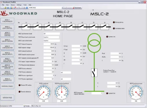
MSLC-2 – Homepage ... 56
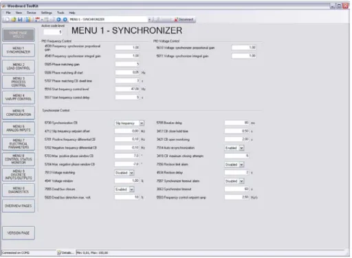
Menu 1 – Synchronizer ... 61
Menu 2 – Load Control ... 65
Menu 3 – Process Control ... 69
Menu 4 – Voltage/Var/PF Control ... 71
Menu 5 – Configuration ... 75
Menu 6 – Analog Inputs ... 87
Menu 7 – Electrical Parameters ... 92
Menu 8 – Control Status Monitor ... 95
Menu 9 – Discrete Inputs / Relay Outputs ... 98
Menu 0 – Diagnostics ... 101
Overview Pages ... 103
Prestart Setup Procedure ... 105
Configuration Menu ... 105
Prestart Segmenting Setup ... 106
Prestart Synchronizer Setup ... 110
Prestart Load Control Setup ... 110
Prestart Process Control Setup ... 110
Prestart Var/Power Factor Control Setup ... 110
MSLC-2 Control Adjustments ... 111
Calibration Check ... 111
Synchronizer Adjustments ... 112
Preliminary Synchronizer Adjustments... 112
Phase Matching Synchronizer ... 112
Slip Frequency Synchronizer ... 113
Final Synchronizer Setup ... 114
Voltage Matching Adjustments ... 114
Preliminary Voltage Matching Setup ... 114
Final Voltage Matching Setup ... 115
Load Control Adjustment ... 115
Base Load Mode Setup ... 115
Remote Base Load ... 115
Import/Export Mode Setup ... 116
Remote Import/Export Setup ... 116
Final Load Control Setup ... 117
Process Control Adjustment ... 118
Var/PF Control Adjustment ... 119
Constant Generator Power Factor Setup ... 119
PF Control At The Utility - Setup ... 120
Remote PF Control At The Utility - Setup ... 120
C
HAPTER4.
S
YNCHRONIZERD
ESCRIPTION... 122
Introduction... 122
Functional Description ... 122
Operating Modes ... 122
Measurement Connections (Examples) ... 124
Dead Bus Closing – Multiple Units ... 136
Voltage Matching ... 137
Phase Matching Synchronizing ... 137
Slip Frequency Synchronizing ... 137
Permissive Mode / Synch-Check Function ... 137
GCB Maximun Closing Attempts ... 138
Auto re-synchronization ... 138
Reclose limit alarm ... 138
Synchronizer Timer ... 138
Logic Charter GCB Closure ... 139
Manual Synchronizing ... 140
Frequency Setpoint ... 140
Voltage Setpoint ... 140
Breaker Close ... 141
Reset Frequency / Voltage Setpoints Back To Rated (50 Hz or 60 Hz) ... 141
C
HAPTER5.
R
EALP
OWERC
ONTROLD
ESCRIPTION... 142
Introduction... 142
MSLC-2 / DSLC-2 Interface ... 142
Base Load Mode ... 142
Import / Export Mode ... 143
Process Control Mode ... 143
Remote Control ... 143
Automatic Power Transfer Control Functions ... 143
Ramping Between Modes ... 143
Utility Unload ... 143
Local Unload ... 144
C
HAPTER6.
V
AR/P
OWERF
ACTORC
ONTROLD
ESCRIPTION... 145
Introduction... 145
Constant Generator Power Factor ... 145
Power Factor Control ... 146
Var Control ... 146
C
HAPTER7.
P
ROCESSC
ONTROLD
ESCRIPTION... 147
Introduction... 147
Description ... 147
C
HAPTER8.
N
ETWORK/
S
YSTEMD
ESCRIPTION... 150
Introduction... 150
Description ... 150
Applications Without Segmenting ... 150
Applications With Segmenting ... 151
Not Supported Applications ... 154
Remote Control by PLC ... 155
Interface Connection Via RS-485 With Modbus Protocol ... 155
C
HAPTER9.
I
NTERFACE... 157
Interface Overview ... 157
Ethernet Load Sharing ... 158
Multi-Master Principle ... 158
Load Share Monitoring ... 158
General Load Share Information ... 158
Modbus Communications ... 159
General Information ... 159
Address Range ... 160
Visualization ... 161
Configuration ... 162
MSLC-2 Interface Remote Control ... 163
Changing Parameter Settings Via Modus ... 169
Parameter Setting... 169
Remotely Resetting The Default Values ... 171
Modbus Parameters ... 173
Serial Interface 1 ... 173
Serial Interface 2 ... 173
Network B – Modbus ... 173
A
PPENDIXA.
T
ECHNICALD
ATA... 174
Environmental Data ... 176
Accuracy ... 177
A
PPENDIXB.
U
SEFULI
NFORMATION... 178
Connecting 24 V Relays ... 178
A
PPENDIXC.
D
ATAP
ROTOCOLS... 179
Data Protocol 5200 ... 179
A
PPENDIXD.
P
ARAMETERO
VERVIEW... 186
Introduction ... 186
Parameter List Columns ... 186
Parameter List ... 187
A
PPENDIXE.
S
ERVICEO
PTIONS... 193
Product Service Options ... 193
Returning Equipment For Repair ... 193
Packing A Control ... 194
Return Authorization Number RAN ... 194
Replacement Parts ... 194
How To Contact Woodward ... 195
Engineering Services ... 196
Figures and Tables
FiguresFigure 1-2: Multiple generators in isolated operation with tie-breaker ... 15
Figure 1-3: Multiple generators in isolated and utility parallel operation with utility- and tie-breaker ... 16
Figure 2-1: Housing MSLC-2 - dimensions ... 19
Figure 2-2: Housing - drill plan ... 20
Figure 2-3: MSLC-2 - terminal arrangement ... 21
Figure 2-4: Wiring diagram - MSLC-2 - 1/2 ... 22
Figure 2-5: Wiring diagram - MSLC-2 - 2/2 ... 23
Figure 2-6: Power supply ... 25
Figure 2-7: Power supply - crank waveform at maximum load ... 25
Figure 2-8: Voltage measuring – system A ... 26
Figure 2-9: VVoltage measuring – system A windings, 3Ph 4W OD ... 27
Figure 2-10: Voltage measuring – system A measuring inputs, 3Ph 4W OD ... 27
Figure 2-11: Voltage measuring – system A windings, 3Ph 4W ... 28
Figure 2-12: Voltage measuring – system A measuring inputs, 3Ph 4W ... 28
Figure 2-13: Voltage measuring – system A windings, 3Ph 3W ... 29
Figure 2-14: Voltage measuring – system A measuring inputs, 3Ph 3W ... 29
Figure 2-15: Voltage measuring – system B ... 30
Figure 2-16: Voltage measuring – system B measuring inputs, 1Ph 2W (phase-neutral) ... 31
Figure 2-17: Voltage measuring – system B measuring inputs, 1Ph 2W (phase-phase) ... 32
Figure 2-18: Voltage measuring – auxiliary system B ... 33
Figure 2-19: Voltage measuring - auxiliary system B PT windings, 3Ph 4W ... 34
Figure 2-20: Voltage measuring - auxiliary system B measuring inputs, 3Ph 4W ... 34
Figure 2-21: Voltage measuring - auxiliary system B PT windings, 3Ph 3W ... 35
Figure 2-22: Voltage measuring - auxiliary system B measuring inputs, 3Ph 3W ... 35
Figure 2-23: Current measuring – system A ... 36
Figure 2-24: Current measuring – system A, L1 L2 L3 ... 37
Figure 2-25: Current measuring - system A, phase Lx ... 37
Figure 2-26: Power measuring - direction of power ... 38
Figure 2-27: Discrete inputs - alarm/control input - positive signal ... 41
Figure 2-28: Discrete inputs - alarm/control input - negative signal ... 41
Figure 2-29: Relay outputs ... 43
Figure 2-30: Analog inputs - wiring two-pole senders using a voltage signal... 45
Figure 2-31: Analog inputs - wiring two-pole senders (external jumper used for current signal) ... 45
Figure 2-32: RS-485 interface #1 - overview ... 46
Figure 2-33: RS-485 Modbus - connection for half-duplex operation ... 46
Figure 2-34: RS-485 Modbus - connection for full-duplex operation ... 46
Figure 2-35: RS-232 interface - overview ... 47
Figure 2-36: RJ-45 interfaces - overview ... 47
Figure 3-1: ToolKit - visualization screen ... 53
Figure 3-2: ToolKit - analog value trending screen ... 53
Figure 3-3: ToolKit - configuration screen ... 54
Figure 3-4: ToolKit -version page ... 55
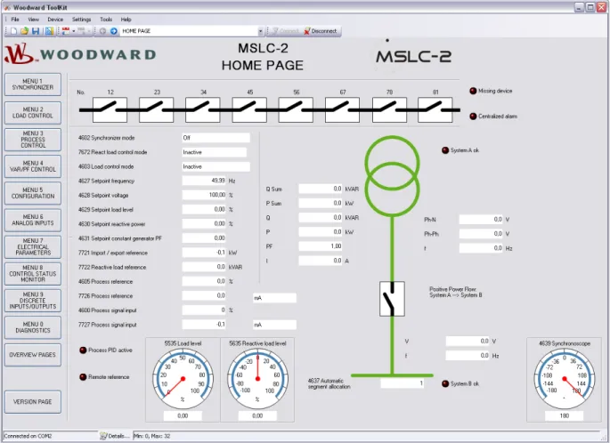
Figure 3-5: ToolKit - home page (MSLC-2 configured as utility breaker control) ... 56
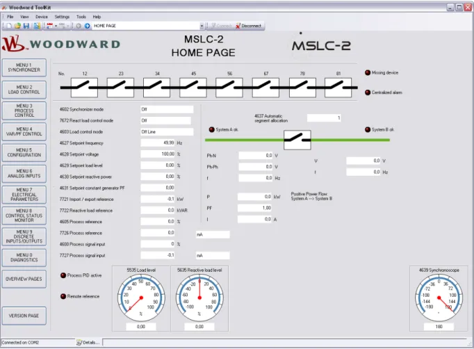
Figure 3-6: ToolKit - home page (MSLC-2 configured as tie-breaker control) ... 57
Figure 3-8: ToolKit - home page - MSLC-2 configured as utility breaker control ... 59
Figure 3-9: ToolKit - home page - MSLC-2 configured as tie-breaker control ... 60
Figure 3-10: ToolKit - home page - segments... 60
Figure 3-11: ToolKit – synchronizer ... 61
Figure 3-13: ToolKit – load control ... 65
Figure 3-15: ToolKit – process control ... 69
Figure 3-17: ToolKit – voltage/var/pf control ... 71
Figure 3-19: ToolKit – configuration ... 75
Figure 3-21: ToolKit – interfaces ... 82
Figure 3-33: ToolKit – control status monitor ... 95
Figure 3-35: ToolKit – discrete inputs / relay outputs... 98
Figure 3-37: ToolKit – diagnostics ... 101
Figure 3-39: ToolKit – DSLC-2 overview page ... 103
Figure 3-40: ToolKit – MSLC-2 overview page ... 104
Figure 3-41: Example of an online diagram ... 106
Figure 3-42: Example of an online diagram with segment numbers and segment connector feedbacks ... 107
Figure 3-43: Example of an online diagram with according network ... 108
Figure 3-44: Example of an online diagram with all required information to setup the units ... 109
Figure 3-45: Power measurement ... 111
Figure 4-1: Synchronizer block diagram ... 123
Figure 4-2: Low voltage system 480 V / 277 V – 3-phase with neutral ... 124
Figure 4-3: Low voltage system 480 V / 277 V – 3-phase with neutral ... 125
Figure 4-4: Low voltage system 480 V – 3-phase with neutral ... 126
Figure 4-5: Low voltage system 600 V / 346 V – 3-phase ... 127
Figure 4-6: Low voltage system 600 V / 346 V – 3-phase ... 128
Figure 4-7: Low voltage system 600 V / 346 V – 3-phase ... 129
Figure 4-8: Low voltage system 600 V / 346 V – 3-phase with neutral ... 130
Figure 4-9: Low voltage system 600 V / 346 V – 3-phase with neutral ... 131
Figure 4-10: Low voltage system 600 V / 346 V – 3-phase with neutral ... 132
Figure 4-11: Low voltage system 600 V / 346 V – 3-phase with neutral ... 133
Figure 4-12: Middle voltage system 20 kV – 3-phase without neutral ... 134
Figure 4-13: Middle voltage system 20 kV – 3-phase without neutral ... 135
Figure 4-14: Dead bus closing – Example of dead busbar closure arbitration ... 136
Figure 4-15: Logic charter CB closure ... 139
Figure 7-1: Diagram process control ... 149
Figure 8-1: Multiple generators in isolated operation without tie-breakers... 151
Figure 8-2: Multiple generators in isolated / parallel to utility operation without tie-breakers ... 151
Figure 8-3: Isolated operation with multiple generator and tie-breaker ... 152
Figure 8-4: Isolated / utility parallel operation with multiple generator and tie-breaker ... 152
Figure 8-5: Isolated / utility parallel operation with multiple generator, tie-breaker and generator group breaker ... 153
Figure 8-6: Isolated operation with multiple generator and tie-breaker (ring option) ... 153
Figure 8-7: Not supported application ... 154
Figure 8-8: Not supported application ... 154
Figure 8-9: Visualization and remote control by PLC via RS-485 interface ... 155
Figure 8-10: Visualization and remote control by PLC via Ethernet Modbus/TCP interface ... 156
Figure 9-1: MSLC-2 - interface overview (housing - side view) ... 157
Figure 9-2: Modbus - visualization configurations ... 161
Figure 9-3: Modbus - sending binary digital orders over interface ... 164
Figure 9-4: Modbus – loss of connection ... 166
Figure 9-7: Modbus - configuration example 1 ... 169
Figure 9-8: Modbus - configuration example 2 ... 170
Figure 9-9: Modbus - configuration example 3 ... 170
Figure 9-10: Modbus - remote control parameter 1701 ... 171
Figure 9-11: Modbus - write register - enable the resetting procedure via RS-232 or Modbus TCP/IP ... 171
Figure 9-12: Modbus - remote control parameter 1701 ... 172
Figure 9-13: Modbus - write register - resetting the default values... 172
Tables
Table 1-1: Manual - overview ... 11
Table 2-1: Conversion chart - wire size ... 24
Table 2-2: Power supply - terminal assignment ... 25
Table 2-3: Voltage measuring – terminal assignment – system A voltage ... 26
Table 2-4: Voltage measuring - terminal assignment – system A, 3Ph 4W OD... 27
Table 2-5: Voltage measuring – terminal assignment – system A, 3Ph 4W ... 28
Table 2-6: Voltage measuring - terminal assignment – system A, 3Ph 3W ... 29
Table 2-7: Voltage measuring - terminal assignment – system B voltage ... 30
Table 2-8: Voltage measuring - terminal assignment – system B, 1Ph 2W (phase-neutral)... 31
Table 2-9: Voltage measuring - terminal assignment – system B, 1Ph 2W (phase-phase) ... 32
Table 2-10: Voltage measuring - terminal assignment - auxiliary system B voltage ... 33
Table 2-11: Voltage measuring - terminal assignment - auxiliary system B, 3Ph 4W ... 34
Table 2-12: Voltage measuring - terminal assignment - auxiliary system B, 3Ph 3W ... 35
Table 2-13: Current measuring - terminal assignment – system A current ... 36
Table 2-14: Current measuring - terminal assignment – system A, L1 L2 L3 ... 37
Table 2-15: Current measuring - terminal assignment - system A, phase Lx ... 37
Table 2-16: Power measuring - terminal assignment ... 38
Table 2-17: Discrete input - terminal assignment 1/2 ... 41
Table 2-18: Discrete input - terminal assignment 2/2 ... 42
Table 2-20: Relay outputs - terminal assignment ... 43
Table 2-21: Analog inputs - terminal assignment - wiring two-pole senders ... 45
Table 2-22: RS-485 interface #1 - pin assignment ... 46
Table 2-23: RS-232 interface - pin assignment ... 47
Table 2-24: RJ-45 interfaces - pin assignment ... 47
Table 3-7: Parameter - homepage ... 58
Table 3-12: Parameter – synchronizer... 64
Table 3-14: Parameter – load control ... 68
Table 3-16: Parameter – process control ... 70
Table 3-18: Parameter – voltage/var/pf control ... 74
Table 3-20: Parameter – configuration ... 81
Table 3-22: Parameter – configuration – interfaces ... 84
Table 3-24: Parameter – configuration – system management ... 87
Table 3-30: Parameter – analog inputs ... 91
Table 3-32: Parameter – electrical parameters ... 94
Table 3-34: Parameter – control status monitor ... 97
Table 3-36: Parameter – discrete inputs / outputs ... 100
Table 3-38: Parameter – diagnostics ... 102
Table 3-29: Parameter – DSLC-2 overview page ... 103
Table 3-30: Parameter – MSLC-2 overview page ... 104
Table 4-1: Low voltage system 480 V / 277 V – 3-phase with neutral ... 124
Table 4-2: Low voltage system 480 V / 277 V – 3-phase with neutral ... 125
Table 4-3: Low voltage system 480 V – 3-phase with neutral ... 126
Table 4-4: Low voltage system 600 V / 346 V – 3-phase ... 127
Table 4-5: Low voltage system 600 V / 346 V – 3-phase ... 128
Table 4-6: Low voltage system 600 V / 346 V – 3-phase ... 129
Table 4-7: Low voltage system 600 V / 346 V – 3-phase with neutral ... 130
Table 4-8: Low voltage system 600 V / 346 V – 3-phase with neutral ... 131
Table 4-9: Low voltage system 600 V / 346 V – 3-phase with neutral ... 132
Table 4-10: Low voltage system 600 V / 346 V – 3-phase with neutral ... 133
Table 4-11: Middle voltage system 20 kV – 3-phase without neutral ... 134
Table 4-12: Middle voltage system 20 kV – 3-phase without neutral ... 135
Table 9-1: MSLC-2 - Interfaces - overview ... 157
Table 9-2: Modbus - address range ... 160
Table 9-3: Modbus - address range block read... 161
Table 9-4: Modbus - address calculation ... 162
Table 9-5: Modbus - data types ... 162
Table 9-6: Modbus – sending setpoint sover interface ... 163
Table 9-13: Modbus - serial interface 1 - parameters ... 173
Table 9-14: Modbus - serial interface 2 – parameters ... 173
Table 9-15: Modbus - TCP/IP Network B– parameters ... 173
Chapter 1.
General Information
Document Overview
≡≡≡≡≡≡≡≡≡≡≡≡≡≡≡≡≡≡≡≡≡≡≡≡≡
This manual describes the Woodward MSLC-2TM Master Synchronizer and Load Control.
Type English German
MSLC-2
DSLC-2 – User Manual 37443 -
MSLC-2 – User Manual this manual 37444 -
Table 1-1: Manual - overview
Intended Use The unit must only be operated in the manner described by this manual. The prerequisite for a proper and safe operation of the product is correct transportation, storage and installation as well as careful opera-tion and maintenance.
NOTE
This manual has been developed for a unit fitted with all available options. Inputs/outputs, functions, configuration screens and other details described, which do not exist on your unit, may be ignored. The present manual has been prepared to enable the installation and commissioning of the unit. Due to the large variety of parameter settings, it is not possible to cover every combination. The manual is therefore only a guide.
Application
≡≡≡≡≡≡≡≡≡≡≡≡≡≡≡≡≡≡≡≡≡≡≡≡≡
The Woodward MSLC-2™ control is the direct successor of the former MSLC™ master synchronizer and load control. The MSLC-2™ is a microprocessor-based overall plant load control designed for use in a system with
Woodward DSLC-2TM (“Digital Synchronizer and Load Control”) controls on each generator to provide utility
synchronizing, paralleling, loading and unloading of a three-phase generating system.
Applications allow up to 32 generators to be paralleled and controlled in conjunction with up to 16 MSLC-2. A
dedicated Ethernet system provides seamless communications between DSLC-2TM and MSLC-2TM units. A
second Ethernet port is provided for customer remote control and monitoring capability using Modbus TCP al-lowing DCS and PLC interfacing. Additionally a Modbus RTU is available through a separate RS-485 port.
MSLC-2 function summary
Original MSLC functions include:• Selectable for phase matching or slip frequency synchronizing between the utility and a local bus with
voltage matching
• Automatic system loading and unloading for bumpless load transfer
• Import/export level control capability
• Process control for cogeneration, pressure, maintenance or other process
• Proportional loading of associated DSLC-2 controls in isochronous load sharing
• Adjustable power factor control
• Built in diagnostics with relay output
• Multifunction adjustable high and low limit alarms and adjustable load switches with relay outputs
• Digital communications network to provide loading and power factor control of individual DSLC-2
equipped generators
Additional MSLC-2 functions include:
• Automatic dead bus closure capability for tie-breakers
• Multiple utility breaker and tie-breaker MSLC-2s on the same bus segment
• One dedicated Ethernet line for precise system communications between all DSLC-2s and MSLC-2s on
the system
• Ethernet Modbus/TCP for remote control and monitoring
• Serial Modbus RS-485 for remote control and monitoring
• Applications with up to 32 DSLC-2 and 16 MSLC-2
• Automatic segment control (self recognizing of the segment)
• Full setup, metering and diagnostic capability through the PC program ToolKit
Synchronizer
≡≡≡≡≡≡≡≡≡≡≡≡≡≡≡≡≡≡≡≡≡≡≡≡≡
Either phase matching or slip frequency synchronizing may be selected. Phase matching provides rapid synchro-nizing for critical standby power applications. Slip frequency synchrosynchro-nizing ensures that the initial flow of power will be either out of the local system (export) or into the local system (import), depending on whether a positive or negative slip is chosen. For both synchronizing methods, the MSLC-2 uses actual slip frequency and breaker delay values to anticipate an adjustable minimum phase difference between the utility and the local bus.
Addi-The MSLC-2 control provides a safe automatic dead bus closure function. Deadbus closing permission is granted to only one DSLC-2 or MSLC-2 control in the whole system through locking techniques done over the commu-nications network.
The MSLC-2, configured as tie-breaker control, allows selecting different closure modes or all modes:
• Alive bus A -> dead bus B
• Dead bus A -> dead bus B
• Alive bus B -> dead bus A
Load Control
≡≡≡≡≡≡≡≡≡≡≡≡≡≡≡≡≡≡≡≡≡≡≡≡≡
The MSLC-2 has 4 load control modes available:
• Base load
• Import/export
• Process
• Utility unload
Load control begins with the breaker closure of the utility and another discrete input selecting the load control mode wanted. If no load control mode is selected the MSLC-2 will be in the offline mode. The system load im-mediately prior to breaker closure is used as the starting base load reference. On command, the adjustable ramp allows smooth, timecontrolled loading into a set import/export level. A ramp pause switch is provided to stop the ramp at any point.
The import/export control is an integrating control. It adjusts the percentage of rated load carried by the individu-al generators, operating in isochronous load sharing, in order to maintain a set import/export or base load level. The MSLC-2 will maintain a constant base load or import/export level even with changing utility frequencies. The MSLC-2 provides switch inputs to allow raising or lowering the internal digital base load or import/export reference. The control also provides a remote analog signal input for reference setting, if desired. (signal variety: 0 to 20mA, 4 to 20mA, 0 to 5V, 1 to 5V and 0 to 10V)
The MSLC-2 is equipped with a utility unload switch, which provides an adjustable time controlled ramp to low-er the base load or import/export level. When the level is below an adjustable threshold, the MSLC-2 issues a breaker open command to separate the utility from the local bus. The ramp pause switch can be used to stop the utility unload at any point. The maximum load that the MSLC-2 can tell the individual generators to carry is their rated loads. So, in the event that the plant load is greater than the capacity of the operating generators, the utility unload will stop when 100% rated load is reached on each of the operating generators. This prevents accidental overloading of the local generators.
The MSLC-2 also includes two adjustable load switches which can be used for external functions or warnings when chosen system load levels are attained. The high and low limit switches may also be activated when 100% or 0% load signal to the generators is reached.
Process Control
≡≡≡≡≡≡≡≡≡≡≡≡≡≡≡≡≡≡≡≡≡≡≡≡≡
A process controller is provided for cogeneration, fluid level maintenance, pressure control or other applications. An adjustable bandwidth signal input filter, flexible PID controller adjustments, selectable for direct or indirect action, allow the process control to be used in a wide variety of applications.
An analog signal input (signal variety: 0 to 20mA, 4 to 20mA, 0 to 5V, 1 to 5V and 0 to 10V) provides the process signal to the MSLC-2. The MSLC-2 includes an internal digital process reference which may be con-trolled by the raise and lower switch contact inputs or by an external analog input signal as remote process refer-ence. The MSLC-2 also has a Modbus address for process reference control. The output of the process control, like the import/export control, is the percentage of rated load setpoint to the individual generators in isochronous load sharing.
An adjustable ramp allows smooth entry and exit from the process control mode. When the process control mode is selected, the load reference is ramped in a direction to reduce the error between the process input and the process reference. When the error is minimized or the reference first reaches either the high or low specified lim-its, the process controllers PID loop is activated. When the load reference output reaches either 100% or 0%, the control will maintain that load reference until process control is established. The MSLC-2 is not capable of over-loading or reverse powering the generators in an attempt to meet the process reference. The high and low limit switches mentioned above can be used to indicate that either too many or too few generators are online to main-tain the process within its limits.
Var/PF Control
≡≡≡≡≡≡≡≡≡≡≡≡≡≡≡≡≡≡≡≡≡≡≡≡≡
The var/PF function controls the power factor on all of the DSLC-2 equipped machines operating in isochronous load sharing. The PF control begins on breaker closure. The MSLC-2 has three modes of Var/PF control (which are selected in Menu 4):
• Constant generator power factor
–
sets the power factor reference on all of the DSLC-2 controls to theinternal reference chosen in the MSLC-2. The power factor can then be adjusted using the voltage raise and lower inputs. The voltage raise command will make the power factor more lagging. Conversely, the voltage lower command will make the power factor more leading.
• Utility tie power factor control
–
adjusts the power factor reference on all of the DSLC-2 controls inisochronous load sharing in order to maintain the power factor across the utility tie.
• Utility tie var control
–
adjusts the power factor reference on all of the DSLC-2 controls in isochronousload sharing in order to maintain the level of vars being imported or exported from the utility.
The var/PF control mode begins with the load control mode selected. The constant generator power factor and the utility tie power factor control can have the reference setting controlled by an analog input (see Menu 6). By clos-ing the voltage raise and lower discrete inputs you can select the analog remote input for reference control.
DSLC-2 / MSLC-2 Systems
≡≡≡≡≡≡≡≡≡≡≡≡≡≡≡≡≡≡≡≡≡≡≡≡≡
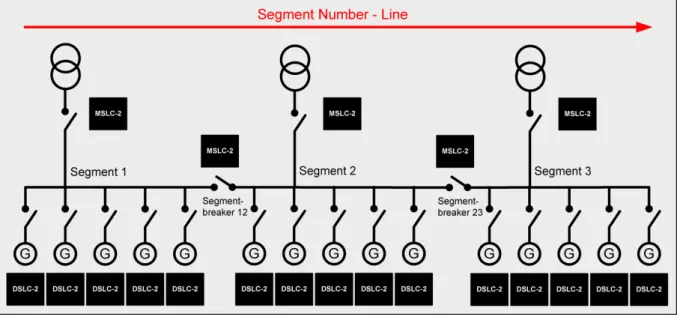
The network addressing of the DSLC-2 / MSLC-2 allows up to 32 DSLC-2s and 16 MSLC-2s in an application. A DSLC-2 and MSLC-2 application can handle 8 segments. Discrete inputs inform the DSLC-2s and MSLC-2s which segments each generator and utilities are operating on. If a MSLC-2 receives a discrete input to activate segment 1 and 2, it will share this information with all controls over the Ethernet bus. It is not necessary to pro-vide a segment activation discrete input to all controls. Segmenting allows the DSLC-2s and MSLC-2s to remain connected thru the Ethernet bus, but be operating on separate load buses.
The DSLC-2 / MSLC-2 system can be applied according to following rules:
• The maximum number of DSLC-2s (Gen-CB) is 32.
• The maximum number of MSLC-2s (Utility- or Tie-CB) is 16.
• The maximum number of segments is 8.
• The segment numbers have to follow a line, which can finally be closed to a ring.
• Only one MSLC-2 can be used as master control, when multiple MSLC-2 are resided in one segment.
o The MSLC-2 with the lower device number will control if multiple Utility MSLC-2s are active
on the same segment
• The generator is not counted as a segment.
• The utility is not counted as a segment.
NOTE
If different MSLC-2s, located in different segments, are connected via a tie-MSLC-2, more than one MSLC-2 is now located in the same segment. The result is the MSLC-2 with the lowest device number becomes the master of all MSLC-2s located in this segment.
Examples:
Chapter 2.
Installation
Electrostatic Discharge Awareness
≡≡≡≡≡≡≡≡≡≡≡≡≡≡≡≡≡≡≡≡≡≡≡≡≡
All electronic equipment is static-sensitive, some components more than others. To protect these components from static damage, you must take special precautions to minimize or eliminate electrostatic discharges. Follow these precautions when working with or near the control.
Before doing maintenance on the electronic control, discharge the static electricity on your body to ground by touching and holding a grounded metal object (pipes, cabinets, equipment, etc.).
Avoid the build-up of static electricity on your body by not wearing clothing made of synthetic materials. Wear cotton or cotton-blend materials as much as possible because these do not store static electric charges as easily as synthetics.
Keep plastic, vinyl and Styrofoam materials (such as plastic or Styrofoam cups, cigarette packages, cellophane wrappers, vinyl books or folders, plastic bottles, etc.) away from the control, modules and work area as much as possible.
Opening the control cover may void the unit warranty.
Do not remove the printed circuit board (PCB) from the control cabinet unless absolutely necessary. If you must remove the PCB from the control cabinet, follow these precautions:
• Ensure that the device is completely voltage-free (all connectors have to be disconnected).
• Do not touch any part of the PCB except the edges.
• Do not touch the electrical conductors, connectors, or components with conductive devices or with
bare hands.
• When replacing a PCB, keep the new PCB in the plastic antistatic protective bag it comes in until you
are ready to install it. Immediately after removing the old PCB from the control cabinet, place it in the antistatic protective bag.
CAUTION
To prevent damage to electronic components caused by improper handling, read and observe the pre-cautions in Woodward manual 82715, Guide for Handling and Protection of Electronic Controls, Printed
Circuit Boards and Modules.
NOTE
The unit is capable to withstand an electrostatic powder coating process with a voltage of up to 85 kV and a current of up to 40 µA.
Unpacking
≡≡≡≡≡≡≡≡≡≡≡≡≡≡≡≡≡≡≡≡≡≡≡≡≡
Before unpacking the control, refer to the inside front cover of this manual for WARNINGS and CAUTIONS. Be careful when unpacking the control. Check for signs of damage such as bent or dented panels, scratches, loose or broken parts. If any damage is found, immediately notify the shipper.
Location
≡≡≡≡≡≡≡≡≡≡≡≡≡≡≡≡≡≡≡≡≡≡≡≡≡
When selecting a location for mounting the MSLC-2 control, consider the following:
• Protect the unit from direct exposure to water or to a condensation-prone environment.
• The continuous operating range of the MSLC-2 control is –40 to +70 °C (–40 to +158 °F).
• Provide adequate ventilation for cooling. Shield the unit from radiant heat sources.
• Do not install near high-voltage, high-current devices.
• Allow adequate space in front of the unit for servicing.
• Do not install where objects can be dropped on the terminals.
• Ground the chassis for proper safety and shielding.
Housing
≡≡≡≡≡≡≡≡≡≡≡≡≡≡≡≡≡≡≡≡≡≡≡≡≡
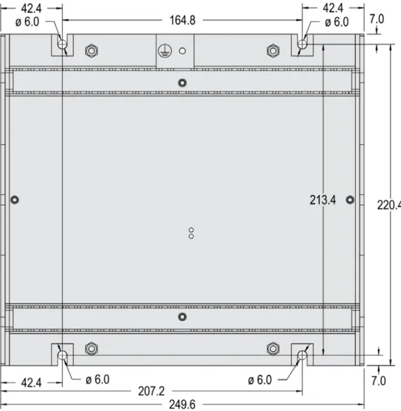
Dimensions
Figure 2-1: Housing MSLC-2 - dimensions Protective Earth
Installation
The unit is to be mounted to the switch cabinet back using four screws with a maximum diameter of 6 mm. Drill the holes according to the dimensions in Figure 2-2 (dimensions shown in mm).
Terminal Arrangement
NOTE
The Protective Earth terminal 61 is not connected on the MSLC-2. The protective earth connection at the sheet metal housing must be used instead (refer to Figure 1-2).
Wiring Diagrams
Connections
≡≡≡≡≡≡≡≡≡≡≡≡≡≡≡≡≡≡≡≡≡≡≡≡≡
WARNING
All technical data and ratings indicated in this chapter are not definite! Only the values indicated in pa-ragraph Appendix A. Technical Data on page 174 are valid!
The following chart may be used to convert square millimeters [mm²] to AWG and vice versa:
AWG mm² AWG mm² AWG mm² AWG mm² AWG mm² AWG mm²
30 0.05 21 0.38 14 2.5 4 25 3/0 95 600MCM 300
28 0.08 20 0.5 12 4 2 35 4/0 120 750MCM 400
26 0.14 18 0.75 10 6 1 50 300MCM 150 1000MCM 500
24 0.25 17 1.0 8 10 1/0 55 350MCM 185
22 0.34 16 1.5 6 16 2/0 70 500MCM 240
Power Supply
WARNING – Protective Earth
Protective Earth (PE) must be connected to the unit to avoid the risk of electric shock. The conductor providing the connection must have a wire larger than or equal to 2.5 mm² (14 AWG). The connection must be performed properly.
Please use the protective earth connection at the sheet metal housing (refer to Figure 2-1 on page 19).
Figure 2-6: Power supply
Figure Terminal Description Amax
A 63 12/24Vdc (8 to 40.0 Vdc) 2.5 mm²
B 64 0 Vdc 2.5 mm²
Table 2-2: Power supply - terminal assignment
Figure 2-7: Power supply - crank waveform at maximum load
NOTE
Woodward recommends to use one of the following slow-acting protective devices in the supply line to terminal 63:
• Fuse NEOZED D01 6A or equivalent or
Voltage Measuring
NOTE
DO NOT use both sets of voltage measuring inputs. The control unit will not measure voltage correctly if the 120 V and 480 V inputs are utilized simultaneously.
NOTE
Woodward recommends protecting the voltage measuring inputs with slow-acting fuses rated for 2 to 6 A.
Voltage Measuring: System A
Figure 2-8: Voltage measuring – system A
Figure Terminal Description Amax
A 29
System A Voltage AØ (L1) 120 Vac 2.5 mm²
B 30 480 Vac 2.5 mm²
C 31
System A Voltage BØ (L2) 120 Vac 2.5 mm²
D 32 480 Vac 2.5 mm²
E 33
System A Voltage CØ (L3) 120 Vac 2.5 mm²
F 34 480 Vac 2.5 mm²
G 35
System A Voltage N 120 Vac 2.5 mm²
H 36 480 Vac 2.5 mm²
Table 2-3: Voltage measuring – terminal assignment – system A voltage
NOTE
If parameter 1800 ("System A PT secondary rated volt.") is configured with a value between 50 and 130 V, the 120 V input terminals must be used for proper measurement.
If parameter 1800 ("System A PT secondary rated volt.") is configured with a value between 131 and 480 V, the 480 V input terminals must be used for proper measurement.
Voltage Measuring: System A
Parameter Setting '
3Ph 4W OD
' (3-phase, 4-wire, Open delta)
A generator system that is connected to the load through a 3-phase, 4-wire connection but have the device wired for a 3-phase, 3-wire installation may have the L2 phase grounded on the secondary side. In this application the device will be configured for 3-phase, 4-wire open delta for correct power measurement.
Figure 2-9: VVoltage measuring – system A windings, 3Ph 4W OD
Figure 2-10: Voltage measuring – system A measuring inputs, 3Ph 4W OD
3Ph 4W OD Wiring terminals Note
Rated voltage (range) [1] 120 V (50 to 130 Veff.) [4] 480 V (131 to 480 Veff.) 1
Measuring range (max.) [1] 0 to 150 Vac [4] 0 to 600 Vac
Figure A C E G B D F H
Voltage Measuring: System A, Parameter Setting '
3Ph 4W
' (3-phase, 4-wire)
Figure 2-11: Voltage measuring – system A windings, 3Ph 4W
Figure 2-12: Voltage measuring – system A measuring inputs, 3Ph 4W
3Ph 4W Wiring terminals Note
Rated voltage (range) [1] 120 V (50 to 130 Veff.) [4] 480 V (131 to 480 Veff.)
2 Measuring range (max.) [1] 0 to 150 Vac [4] 0 to 600 Vac
Figure A C E G B D F H
MSLC-2 terminal 29 31 33 35 30 32 34 36
Phase L1 / AØ L2 / BØ L3 / CØ N L1 / AØ L2 / BØ L3 / CØ N
Table 2-5: Voltage measuring – terminal assignment – system A, 3Ph 4W L1 L2 N L3 N A1 A2 A B B2 B1 C C2 C1 L1 L2 N L3 N A1 A2 A B C6 C5 B6 B5 A5 A6 B2 B1 C C2 C1 L1 L2 N L3 N A1 A2 A B B6 B5 A5 A6 C C6 C5 B2 B1 C2 C1
Voltage Measuring: System A, Parameter Setting '
3Ph 3W
' (3-phase, 3-wire)
Figure 2-13: Voltage measuring – system A windings, 3Ph 3W
Figure 2-14: Voltage measuring – system A measuring inputs, 3Ph 3W
3Ph 3W Wiring terminals Note
Rated voltage (range) [1] 120 V (50 to 130 Veff.) [4] 480 V (131 to 480 Veff.) 3
Measuring range (max.) [1] 0 to 150 Vac [4] 0 to 600 Vac
Figure A C E G B D F H
MSCL-2 terminal 29 31 33 35 30 32 34 36
Phase L1 / AØ L2 / BØ L3 / CØ --- L1 / AØ L2 / BØ L3 / CØ ---
Table 2-6: Voltage measuring - terminal assignment – system A, 3Ph 3W L1 L2 L3 B2 C2 C1 A1 A2 B1 A B C L1 L2 L3 B1 B2 C6 C5 A1 A2 B5 B6 A B C C2 C1 A5 A6
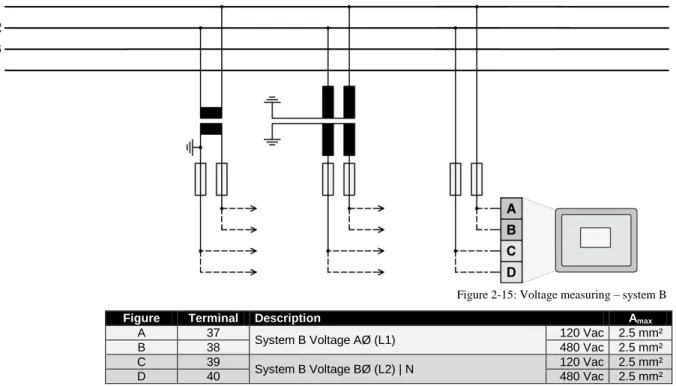
Voltage Measuring: System B
Figure 2-15: Voltage measuring – system B
Figure Terminal Description Amax
A 37
System B Voltage AØ (L1) 120 Vac 2.5 mm²
B 38 480 Vac 2.5 mm²
C 39
System B Voltage BØ (L2) | N 120 Vac 2.5 mm²
D 40 480 Vac 2.5 mm²
Table 2-7: Voltage measuring - terminal assignment – system B voltage
NOTE
If parameter 1803 ("System B PT secondary rated voltage") is configured with a value between 50 and 130 V, the 120 V input terminals must be used for proper measurement.
If parameter 1803 ("System B PT secondary rated voltage") is configured with a value between 131 and 480 V, the 480 V input terminals must be used for proper measurement.
Voltage Measuring: System B, Parameter Setting '
1Ph 2W
' (1-phase, 2-wire)
NOTE
The 1-phase, 2-wire measurement may be performed phase-neutral or phase-phase. Please note to configure and wire the MSLC-2 consistently. Refer to the chapter Configuration & Operation.
'1Ph 2W' Phase-Neutral Measuring
Figure 2-16: Voltage measuring – system B measuring inputs, 1Ph 2W (phase-neutral)
1Ph 2W Wiring terminals Note
Rated voltage (range) [1] 120 V (50 to 130 Veff.) [4] 480 V (131 to 480 Veff.)
4 Measuring range (max.) [1] 0 to 150 Vac [4] 0 to 600 Vac
Figure A C --- --- B D --- ---
MSLC-2 terminal 37 39 --- --- 38 40 --- ---
Phase L1 / AØ N --- --- L1 / AØ N --- ---
'1Ph 2W' Phase-Phase Measuring
Figure 2-17: Voltage measuring – system B measuring inputs, 1Ph 2W (phase-phase)
1Ph 2W Wiring terminals Note
Rated voltage (range) [1] 120 V (50 to 130 Veff.) [4] 480 V (131 to 480 Veff.)
5 Measuring range (max.) [1] 0 to 150 Vac [4] 0 to 600 Vac
Figure A C --- --- B D --- ---
MSLC-2 terminal 37 39 --- --- 38 40 --- ---
Phase L1 / AØ L2 / BØ --- --- L1 / AØ L2 / BØ --- ---
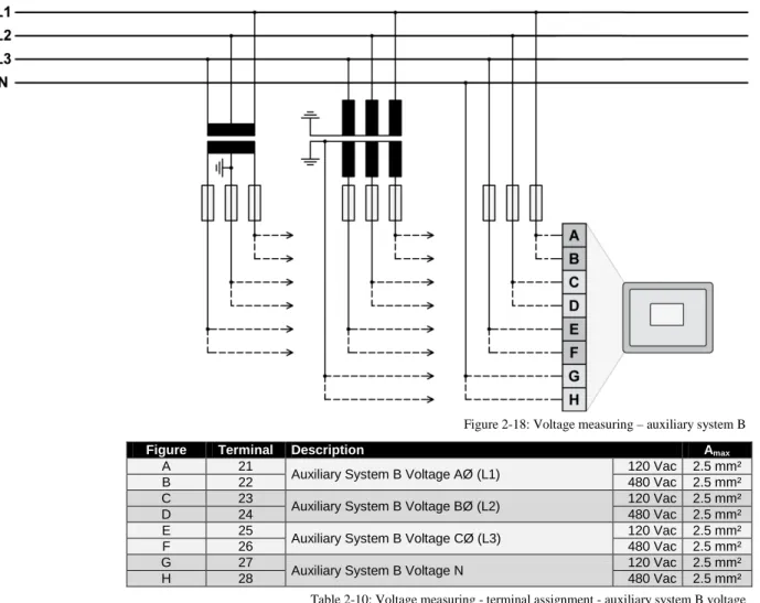
Voltage Measuring: Auxiliary System B
Figure 2-18: Voltage measuring – auxiliary system B
Figure Terminal Description Amax
A 21
Auxiliary System B Voltage AØ (L1) 120 Vac 2.5 mm²
B 22 480 Vac 2.5 mm²
C 23
Auxiliary System B Voltage BØ (L2) 120 Vac 2.5 mm²
D 24 480 Vac 2.5 mm²
E 25
Auxiliary System B Voltage CØ (L3) 120 Vac 2.5 mm²
F 26 480 Vac 2.5 mm²
G 27
Auxiliary System B Voltage N 120 Vac 2.5 mm²
H 28 480 Vac 2.5 mm²
Table 2-10: Voltage measuring - terminal assignment - auxiliary system B voltage
NOTE
If parameter 1803 ("System B PT secondary rated voltage") is configured with a value between 50 and 130 V, the 120 V input terminals must be used for proper measurement.
If parameter 1803 ("System B PT secondary rated voltage") is configured with a value between 131 and 480 V, the 480 V input terminals must be used for proper measurement.
NOTE
If the MSLC-2 is intended to be operated in parallel with the mains, the mains voltage measuring inputs must be connected. If an external mains decoupling is performed, jumpers between system B and aux-iliary system B voltage measuring inputs may be installed.
Voltage Measuring: Auxiliary System B, Parameter Setting '
3Ph 4W
' (3-phase, 4-wire)
Figure 2-19: Voltage measuring - auxiliary system B PT windings, 3Ph 4W
Figure 2-20: Voltage measuring - auxiliary system B measuring inputs, 3Ph 4W
3Ph 4W Wiring terminals Note
Rated voltage (range) [1] 120 V (50 to 130 Veff.) [4] 480 V (131 to 480 Veff.)
6 Measuring range (max.) [1] 0 to 150 Vac [4] 0 to 600 Vac
Figure A C E G B D F H
MSLC-2 terminal 21 23 25 27 22 24 26 28
Phase L1 / AØ L2 / BØ L3 / CØ N L1 / AØ L2 / BØ L3 / CØ N
Table 2-11: Voltage measuring - terminal assignment - auxiliary system B, 3Ph 4W L1 L2 N L3 N A1 A2 A B B2 B1 C C2 C1 L1 L2 N L3 N A1 A2 A B C6 C5 B6 B5 A5 A6 B2 B1 C C2 C1 L1 L2 N L3 N A1 A2 A B B6 B5 A5 A6 C C6 C5 B2 B1 C2 C1
Voltage Measuring: Auxiliary System B, Parameter Setting '
3Ph 3W
' (3-phase, 3-wire)
Figure 2-21: Voltage measuring - auxiliary system B PT windings, 3Ph 3W
Figure 2-22: Voltage measuring - auxiliary system B measuring inputs, 3Ph 3W
3Ph 3W Wiring terminals Note
Rated voltage (range) [1] 120 V (50 to 130 Veff.) [4] 480 V (131 to 480 Veff.) 7
Measuring range (max.) [1] 0 to 150 Vac [4] 0 to 600 Vac
Figure A C E G B D F H
MSLC-2 terminal 21 23 25 27 22 24 26 28
Phase L1 / AØ L2 / BØ L3 / CØ --- L1 / AØ L2 / BØ L3 / CØ ---
Table 2-12: Voltage measuring - terminal assignment - auxiliary system B, 3Ph 3W L1 L2 L3 B2 C2 C1 A1 A2 B1 A B C L1 L2 L3 B1 B2 C6 C5 A1 A2 B5 B6 A B C C2 C1 A5 A6
Current Measuring
CAUTION
Before disconnecting the device, ensure that the current transformer/CT is short-circuited.
System A Current
NOTE
Generally, one line of the current transformers secondary is to be grounded close to the CT.
Figure 2-23: Current measuring – system A
Figure Terminal Description Amax
A 8 System A current C (L3) – X1 2.5 mm² B 7 System A current C (L3) – X2 2.5 mm² C 6 System A current B (L2) – X1 2.5 mm² D 5 System A current B (L2) – X2 2.5 mm² E 4 System A current A (L1) – X1 2.5 mm² F 3 System A current A (L1) – X2 2.5 mm²
Current Measuring: System A, Parameter Setting '
L1 L2 L3
'
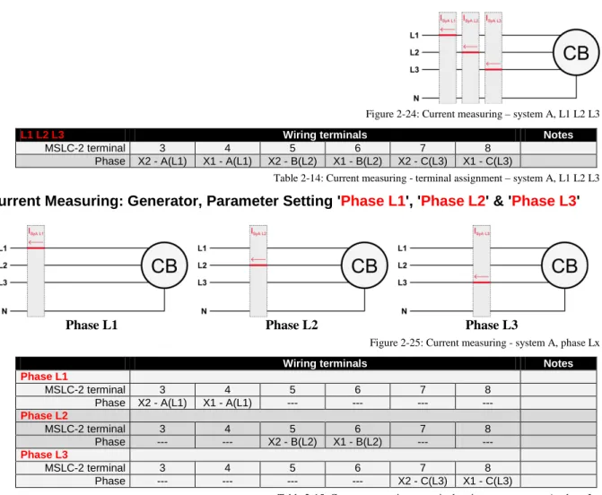
Figure 2-24: Current measuring – system A, L1 L2 L3
L1 L2 L3 Wiring terminals Notes
MSLC-2 terminal 3 4 5 6 7 8
Phase X2 - A(L1) X1 - A(L1) X2 - B(L2) X1 - B(L2) X2 - C(L3) X1 - C(L3)
Table 2-14: Current measuring - terminal assignment – system A, L1 L2 L3
Current Measuring: Generator, Parameter Setting '
Phase L1
', '
Phase L2
' & '
Phase L3
'
Phase L1 Phase L2 Phase L3
Figure 2-25: Current measuring - system A, phase Lx
Wiring terminals Notes
Phase L1
MSLC-2 terminal 3 4 5 6 7 8
Phase X2 - A(L1) X1 - A(L1) --- --- --- --- Phase L2 MSLC-2 terminal 3 4 5 6 7 8 Phase --- --- X2 - B(L2) X1 - B(L2) --- --- Phase L3 MSLC-2 terminal 3 4 5 6 7 8 Phase --- --- --- --- X2 - C(L3) X1 - C(L3)
Power Measuring
If the unit's current transformers are wired according to the diagram shown, the following values are displayed.
Utility Breaker MSLC-2
Parameter Description Sign displayed
Mains real power Importing Kw (from Utility) Powerflow from System A to System B
+ Positive KW
Mains real power Exporting Kw (to Utility) Powerflow from System A to System B
- Negative KW
Mains power factor (cos φ) Inductive / lagging + Positive Mains power factor (cos φ) Capacitive / leading - Negative
Tie-Breaker MSLC-2
Parameter Description Sign displayed
System A real power Powerflow from System A to System B in kW
+ Positive System A real power Powerflow from System A to
System B in kW
- Negative System A power factor (cos φ) Inductive / lagging
reactive-powerflow from System A to System B
+ Positive
System A power factor (cos φ) Capacitive / leading reacti-vepowerflow from System A to System B
- Negative
Figure 2-26: Power measuring - direction of power
Figure Terminal Description Amax
A 3 X2 A (L1) System A Current 2.5 mm²
B 4 X1 A (L1) System A Current 2.5 mm²
Power Factor Definition
The phasor diagram is used from the generator's view. Power factor is defined as follows.
Power Factor is defined as a ratio of the real power to apparent power. In a purely resistive circuit, the voltage and current waveforms are instep resulting in a ratio or power factor of 1.00 (often referred to as unity). In an in-ductive circuit the current lags behind the voltage waveform resulting in usable power (real power) and unusable power (reactive power). This results in a positive ratio or lagging power factor (i.e. 0.85lagging). In a capacitive circuit the current waveform leads the voltage waveform resulting in usable power (real power) and unusable power (reactive power). This results in a negative ratio or a leading power factor (i.e. 0.85leading).
Inductive: Electrical load whose current waveform lags the voltage waveform thus having a lagging pow-er factor. Some inductive loads such as electric motors have a large startup current requirement resulting in lagging power factors.
Capacitive: Electrical load whose current waveform leads the voltage waveform thus having a leading power factor. Some capacitive loads such as capacitor banks or buried cable result in leading power factors.
Different power factor displays at the unit: i0.91 (inductive)
lg.91 (lagging)
c0.93 (capacitive) ld.93 (leading) Reactive power display at the unit:
70 kvar (positive) -60 kvar (negative)
Output at the interface:
+ (positive) - (negative)
In relation to the voltage, the current is
lagging leading
The generator is
over excited under excited
Control: If the control unit is equipped with a power factor controller while in parallel with the utility: A voltage lower "-" signal is output as long as the
measured value is "more inductive" than the reference setpoint
Example: measured = i0.91; setpoint = i0.95
A voltage raise "+" signal is output as long as the measured value is "more capacitive" than the refer-ence setpoint
Phasor diagram:
Discrete Inputs
Discrete Inputs: Signal Polarity
The discrete inputs are electrically isolated which permits the polarity of the connections to be either positive or negative.
NOTE
All discrete inputs must use the same polarity, either positive or negative signals, due to the common ground.
Discrete Inputs: Positive Polarity Signal
Figure 2-27: Discrete inputs - alarm/control input - positive signal
Discrete Inputs: Negative Polarity Signal
Figure 2-28: Discrete inputs - alarm/control input - negative signal
Terminal Description Amax Term. Com. A B 66 GND com-mon ground
67 Discrete input [DI 01] {all} Check 2.5 mm² 68 Discrete input [DI 02] {all} Permissive 2.5 mm² 69 Discrete input [DI 03] {all} Run 2.5 mm² 70 Discrete input [DI 04] {all} CB Aux 2.5 mm² 71 Discrete input [DI 05] {all} Voltage Raise 2.5 mm² 72 Discrete input [DI 06] {all} Voltage Lower 2.5 mm² 73 Discrete input [DI 07] {all} Base Load 2.5 mm² 74 Discrete input [DI 08] {all} Utility Unload 2.5 mm² 75 Discrete input [DI 09] {all} Ramp Pause 2.5 mm² 76 Discrete input [DI 10] {all} Setpoint Raise 2.5 mm² 77 Discrete input [DI 11] {all} Setpoint Lower 2.5 mm² 78 Discrete input [DI 12] {all} Process Control 2.5 mm² Table 2-17: Discrete input - terminal assignment 1/2
Terminal Description Amax Term. Com. A B 152 GND com-mon ground
141 Discrete input [DI 13] {all} Segment No. 12 Act. 2.5 mm² 142 Discrete input [DI 14] {all} Segment No. 23 Act. 2.5 mm² 143 Discrete input [DI 15] {all} Segment No. 34 Act. 2.5 mm² 144 Discrete input [DI 16] {all} Segment No. 45 Act. 2.5 mm² 145 Discrete input [DI 17] {all} Segment No. 56 Act. 2.5 mm² 146 Discrete input [DI 18] {all} Segment No. 67 Act. 2.5 mm² 147 Discrete input [DI 19] {all} Segment No. 78 Act. 2.5 mm² 148 Discrete input [DI 20] {all} Segment No. 81 Act. 2.5 mm² 149 Discrete input [DI 21] {all} Imp./Exp. Control 2.5 mm² 150 Discrete input [DI 22] {all} Modbus Reset 2.5 mm² 151 Discrete input [DI 23] {all} Reserved 2.5 mm² Table 2-18: Discrete input - terminal assignment 2/2
DI CB AUX DI Utility Unload DI Base Load DI Imp/Exp Control DI Process Control DI Ramp Pause DI Setpoint Raise DI Setpoint Lower Off Line 0 x x x x x x x Base Load 1 0 1 0 0 0 0 0
Base Load Raise 1 0 1 0 0 0 1 0
Base Load Lower 1 0 1 0 0 0 0 1
Base Load 1 Remote 1 0 1 0 0 0 1 1 Utility Unload 2 1 1 x x x 0 x x Local Unload 3 1 0 1 0 0 0 0 1 Ramp Pause 4 1 x x x x 1 x x Import/ Export mode 1 0 x 1 0 0 0 0 I/E Raise 1 0 x 1 0 0 1 0 I/E Lower 1 0 x 1 0 0 0 1 I/E Remote 1 1 0 x 1 0 0 1 1 Process Control 1 0 x x 1 0 0 0 Process Raise 1 0 x x 1 0 1 0 Process Lower 1 0 x x 1 0 0 1 Process Remote 1 1 0 x x 1 0 1 1
Table 2-19: Load control modes MSLC-2 1 Remote reference is activated by closing both setpoint raise and setpoint lower switches at the same time.
2 The MSLC-2 can only load the associated generators to 100%. If this is not enough capacity to unload the utility, the unload ramps stops at 100% rated load on the associated generators. The generator high limit alarm, if enabled, will activate at this time.
3 The local plant unload is accomplished by switching to base load mode and supplying a continuous setpoint lower command. 4 The ramp pause command will pause all ramps in any mode.
Relay Outputs
Figure 2-29: Relay outputs
Terminal Description Amax
Term. Com.
A B Form A, N.O. make contact Type
42 41 Relay output [R 01] {all} Alarm (Self Test OK) N.O. 2.5 mm² 43
46
Relay output [R 02] {all} Reserve N.O. 2.5 mm² 44 Relay output [R 03] {all} High Limit N.O. 2.5 mm² 45 Relay output [R 04] {all} Low Limit N.O. 2.5 mm² 48 47 Relay output [R 05] {all} Breaker Open N.O. 2.5 mm² 50 49 Relay output [R 06] {all} Breaker Close N.O. 2.5 mm² 52 51 Relay output [R 07] {all} Lcl./Gen. Breaker Open N.O. 2.5 mm² 54 53 Relay output [R 08] {all} Alarm 1 N.O. 2.5 mm² 56 55 Relay output [R 09] {all} Alarm 2 N.O. 2.5 mm² 57
60
Relay output [R 10] {all} Alarm 3 N.O. 2.5 mm² 58 Relay output [R 11] {all} Load Switch 1 N.O. 2.5 mm² 59 Relay output [R 12] {all} Load Switch 2 N.O. 2.5 mm²
N.O.-normally open (make) contact
DO Alarm DO Reserve DO High Limit DO Low Limit DO Breaker Open DO Breaker Close DO LCL/ Gen Breaker Open DO Alarm 1 DO Alarm 2 DO Alarm 3 DO Load switch 1 DO Load switch 2 Self Test x Reserve x
High load limit High process limit High voltage limit
x Low load limit
Low process limit Low voltage limit
x Utility Unload (DI
8) x
Synchronization-dead bus closure x
Local Generator Breaker open (DI 11)
x Synchronizer
timeout Reclose limit High load limit Low load limit High process limit Low process limit Low voltage limit, High voltage limit Voltage range limit Communication error Missing member Centralized alarm CB open fail x x x Load switch 1 x Load switch 2 x
NOTE
Refer to Appendix B: Connecting 24 V Relays on page 178 for interference suppressing circuits when connecting 24 V relays.
Analog Inputs
The following senders may be used for the analog inputs:
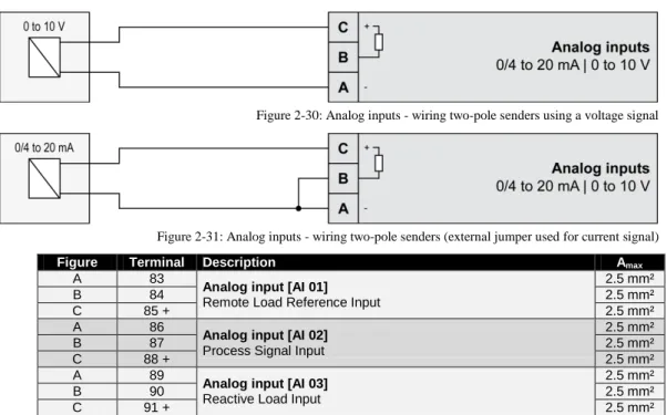
• 0 to 20mA • 4 to 20mA • 0 to 10V • 0 to 5V • 1 to 5V
Wiring Examples
Figure 2-30: Analog inputs - wiring two-pole senders using a voltage signal
Figure 2-31: Analog inputs - wiring two-pole senders (external jumper used for current signal)
Figure Terminal Description Amax
A 83
Analog input [AI 01] Remote Load Reference Input
2.5 mm²
B 84 2.5 mm²
C 85 + 2.5 mm²
A 86
Analog input [AI 02] Process Signal Input
2.5 mm²
B 87 2.5 mm²
C 88 + 2.5 mm²
A 89
Analog input [AI 03] Reactive Load Input
2.5 mm²
B 90 2.5 mm²
C 91 + 2.5 mm²
Interfaces
RS-485 Serial Interface (Serial Interface #2)
Figure 2-32: RS-485 interface #1 - overview
Terminal Description Amax
1 not connected N/A
2 B (TxD+) N/A
3 not connected N/A
4 B' (RxD+) N/A
5 not connected N/A
6 not connected N/A
7 A (TxD-) N/A
8 not connected N/A
9 A' (RxD-) N/A
Table 2-22: RS-485 interface #1 - pin assignment
Half-Duplex with Modbus on RS-485
Figure 2-33: RS-485 Modbus - connection for half-duplex operation
Full-Duplex with Modbus on RS-485
RS-232 Serial Interface (Serial Interface #1)
Figure 2-35: RS-232 interface - overview
Terminal Description Amax
1 not connected N/A
2 RxD (receive data) N/A
3 TxD (transmit data) N/A
4 not connected N/A
5 GND (system ground) N/A
6 not connected N/A
7 RTS (request to send) N/A
8 CTS (clear to send) N/A
9 not connected N/A
Table 2-23: RS-232 interface - pin assignment
RJ-45 Ethernet Interfaces (Network A, Network B)
Figure 2-36: RJ-45 interfaces - overview
Terminal Description Amax
1 Tx+ N/A
2 Tx- N/A
3 Rx+ N/A
4 not connected N/A
5 not connected N/A
6 Rx- N/A
7 not connected N/A
8 not connected N/A
Chapter 3.
Configuration & Operation
Configuration Via PC
≡≡≡≡≡≡≡≡≡≡≡≡≡≡≡≡≡≡≡≡≡≡≡≡≡
Install ToolKit Configuration and Visualization Software
NOTE
Woodward’s ToolKit software is required to configure the unit via PC.
ToolKit Version 3.6.0 or higher
Install ToolKit Software
1. Please insert the enclosed Product CD in the CD-ROM drive of your computer
2. The CD is going to start automatically (autostart function needs to be activated)
3. Please go to the section “Software” and follow the instructions described there
Alternatively ToolKit can be downloaded from our Website. Please proceed as follows:
1. Go to http://www.woodward.com/software
2. Select ToolKit in the list and click the “Go” button
3. Click “More Info” to get further information about ToolKit
4. Choose the preferred software version and click “Download”
5. Now you need to login with your e-mail address or register first
6. The download will start immediatly
Minimum system requirements for ToolKit:
• Microsoft Windows® 7, Vista, XP (32- & 64-bit)
• Microsoft .NET Framework Ver. 3.5
• 600 MHz Pentium® CPU
• 96 MB of RAM
• Minimum 800 by 600 pixel screen with 256 colors
• Serial Port
Install ToolKit Configuration Files
1. Please insert the enclosed Product CD in the CD-ROM drive of your computer 2. The CD is going to start automatically (autostart function needs to be activated)
3. Please go to the section “Configuration Files” and follow the instructions described there
Alternatively ToolKit configuration files can be downloaded from our Website. Please proceed as follows:
1. Go to http://www.woodward.com/software/configfiles/
2. Please insert the part number (P/N) and revision of your device into the corresponding fields
3. Select ToolKit in the application type list
4. Click “Search”
NOTE
ToolKit is using the following files: *.WTOOL
File name composition: [P/N1]*1-[Revision]_[Language ID]_[P/N2]*2-[Revision]_[# of visualized gens].WTOOL
Example file name: 8440-1234-NEW_US_5418-1234-NEW.WTOOL
Content of the file: Display screens and pages for online configuration, which are associated with the respective *.SID file
*.SID
File name composition: [P/N2]*2-[Revision].SID Example file name: 5418-1234-NEW.SID
Content of the file: All display and configuration parameters available in ToolKit *.WSET
File name composition: [user defined].WSET Example file name: easYgen_settings.WSET
Content of the file: Default settings of the ToolKit configuration parameters provided by the SID file or user-defined settings read out of the unit.
*1 P/N1 = Part number of the unit
Starting ToolKit Software
1. Start ToolKit via Windows Start menu -> Programs ->Woodward -> ToolKit 3.x
2. Please press the button “Open Tool”
3. Go to the “Application” folder and open then the folder equal to the part number (P/N) of your device
(e.g. 8440-1234). Select the wtool file (e.g. 8440-1234-NEW_US_5418-1234-NEW.wtool) and click “Open” to start the configuration file
Configure ToolKit Software
1. Start the configuration by using the toolbar. Please go to Tools -> Options
2. The options window will be displayed
a. Adjust the default locations of the configuration files
b. The displayed language can be selected here
3. The changes become effective after clicking “OK”
NOTE
Please use the ToolKit online help for further information.
b a