Standard for Performing a Failure Mode and Effects Analysis (FMEA) and Establishing a Critical Items List (CIL) (DRAFT)
Flight Assurance Procedure (FAP) – 322 - 209 Preface
P.1 Purpose
An FMEA can be described as a systematic group of activities intended to:
(a) recognize and evaluate the potential failure(s) of an item or process and the effects of that failure,
(b) identify actions that could eliminate or reduce the likelihood of the potential failure occurring (probability of occurrence)
(c) document the process.
This Standard defines the who, what, why, when, and how related to the performance of a Failure Modes and Effects Analysis (FMEA) and establishing a Critical Items List (CIL). Why an FMEA performed – the underlying intent of performing an FMEA
When an FMEA performed – When in the Program Cycle FMEAs are performed. FMEAs performed during the preliminary and detailed design phases of a program have as a purpose the iteration of the design to remove critical and high priority failure modes. FMEA iterations performed later are used to validate the design has no critical or high priority failure modes remaining after corrective action has been implemented.
Who performs the FMEA – which personnel are involved in performing each type of FMEA What is contained in an FMEA – the expected information that is input and output during the performance of an FMEA
How the FMEA is performed – the actual step by step approach to performing an FMEA The Critical Items List collects information developed by the FMEA identifying specific systems, sub-systems, functions, components, piece parts, and/or processes that if failed present risk to human life or limb, mission success, or destruction of spacecraft.
P.2 Applicability
This standard is applicable to all Missions, Spacecraft, Instruments, Ground Systems, systems, sub-systems, software and components developed by, contracted by, or manufactured by NASA Goddard Space Flight Center (GSFC) and/or any subsidiary facility. Programs initiated outside of GSFC that have required FMEA procedures that meet or exceed the requirements contained herein shall take precedence over this standard. Contracted facilities and other NASA sites or Partner sites that use FMEA procedures that meet or exceed the requirements of this standard may use those procedures, provided a copy of that procedure is submitted which each FMEA prepared.
P.3 Authority P.4 References
GPR 7120.4A Risk Management
Analysis
SAE J1739 Potential Failure Mode and Effects Analysis in Design (Design FMEA), Potential Failure Mode and Effects Analysis in Manufacturing and Assembly Processes (Process FMEA), and Potential Failure Mode and Effects Analysis for Machinery (Machinery FMEA)
P-302-720 Performing a Failure Mode and Effects Analysis P.5 Cancellation
Flight Assurance Procedure P-302-720 PERFORMING A FAILURE MODE AND EFFECTS ANALYSIS
P.6 Safety
Failure modes identified as affecting Safety shall be reported to the cognizant Project Safety Manager for inclusion in the appropriate safety analysis.
P.7 Training
Training in Failure Mode and Effects Analysis shall be made available to all personnel participating in the FMEA process.
P.8 Records P.9 Metrics P.10 Definitions
1. Item under development – a mission, spacecraft, instrument, system, subsystem, software, or component that is undergoing development at NASA Goddard Space Flight Center or at a contractor facility.
2. Functional Block Diagram - A diagram that shows by concise visual shorthand the various inputs and outputs required to perform a function.
3. Interface - The point or area where a relationship exists between two or more parts, systems, programs, persons, or procedures wherein physical and/or functional compatibility is required.
4. Failure Mode and Effects Analysis (FMEA) - A procedure by which each credible failure mode of each item from a low indenture level to the highest is analyzed to determine the effects on the system and to classify each potential failure mode in accordance with the severity of its effect. FMEA typically assumes that the item under analysis was properly manufactured, and was working immediately before failure. Due to the special nature of spacecraft, launch vehicles, and other NASA hardware, this assumption does not hold true. The impact of faults due to the assembly of spacecraft to launch vehicles after I&T; the effects of shock and vibration due to launch, injection into orbit, powered cruise, deployment of solar panels, instruments, covers, etc. must be addressed in the FMEA. 5. Failure Mode - A particular way in which an item fails, to perform its intended function
such as fracture of a structural member bearing a load or short circuit in a power amplifier. The failure mode is normally observed by inspection of the item or functional testing. Description of failure mode depends upon the indenture level and item function.. 6. Failure Mechanism – The actual physical process leading to a failure mode. . (i.e.
shorted capacitor due to overstress voltage surge,) software failure due to inability to handle input values, process failure due to misinterpretation of ambiguous instruction, etc.).).
7. Failure Effect – the impact a particular Failure Mode has at the Local Level (Component or Sub-Assembly), Next Higher Level (sub-system or System), and Mission Level. 8. Occurrence - A numerical value assigned to the likelihood that a failure mode, due to a
certain cause, will occur.
9. Severity - A numerical value assessing the seriousness of the potential failure effect. 10. Mitigation – A numerical value assigned to the ability of a design to mitigate the
potential failure effect.
11. Detection - A numerical value assigned to the ability of a process to prevent, detect, or minimize the impact of a potential failure.
12. Risk Priority Number (RPN) - The product of Occurrence, Severity, and Mitigation or Detection values. Used to prioritize risks from potential failure modes.
13. Failure Mode Dictionary – a document that identifies failure modes for standard functional or hardware items (i.e. Short or Open for a Diode)
14. Indenture Levels - The hierarchy of hardware levels from the part to the component to the subsystem to the system, etc.
15. Redundancy - More than one independent means of performing a function. There are different kinds of redundancy, including:
a. Operational - Redundant items, all of which are energized during the operating cycle; includes load-sharing, wherein redundant items are connected in a manner such that upon failure of one item, the other will continue to perform the function. It is not necessary to switch out the failed item or switch in the redundant one. b. Cold Standby - Items that are inoperative (have no power applied) until they are
switched in upon failure of the primary item.
c. Like Redundancy - Identical items performing the same function. d. Unlike Redundancy - Nonidentical items performing the same function. e. Functional Redundancy/Operational Workarounds
16. Process Integrity - Related to process performance within specification with normal oversight and supervision, and without the need for special management intervention. 17. Process customer. A NASA GSFC department, contractor, sub- contractor, project or
program that receives outputs from the process under analysis.
18. Process owner. A NASA GSFC department, contractor, sub- contractor, project or program that has control over the process under analysis.
19. Process supplier. A NASA GSFC department, contractor, sub- contractor, project or program that provides inputs to the process under analysis.
20. Critical Items List - Chapter 1 Functional FMEA 1.1 Requirements
A Functional FMEA is performed as soon as sufficient information is available to construct a functional block diagram of the item under development. In order to perform a Functional FMEA, the following information, as a minimum, is required.
a) A functional block diagram of the item under development broken down to the subsystem and component level.
b) A description of each function depicted in the functional block diagram including required inputs and outputs for each block.
c) The manner in which each of the required outputs can fail (i.e. low output, wrong frequency, incorrect motion, etc.).
d) The impact or effect of loss of each functional output depicted in the functional block diagram on the instrument, spacecraft, and/or mission. (the impacts or effects may be developed using a team approach to performing the Functional FMEA)
e) The compensating provisions designed into the item to mitigate the effects of a functional output failure (i.e. redundancy, alternate operating modes, etc.). The Functional FMEA is maintained as a living document throughout the life of a Project/Program. For example, when changes are made to the functional block diagram, the Functional FMEA shall be updated to address these changes. 1.2 Applicability
A Functional FMEA is performed for Mission, Spacecraft, Instrument, Ground System, systems, sub-systems, software and component during Phase A of the development process.
1.3 Methodology
The Functional FMEA should whenever possible be performed by an FMEA Team consisting of a Reliability Engineer, Systems Engineer, Electrical Engineer, Mechanical Engineer, I&T Engineer, and Mission Operations Engineer.
The FMEA Process assumes that all inputs to the Item, System, or Mission under analysis are within specification and failure modes occur one at a time. (i.e. when evaluating a communications system on a spacecraft, the signals from the Earth station are assumed to be within specified limits at all times)
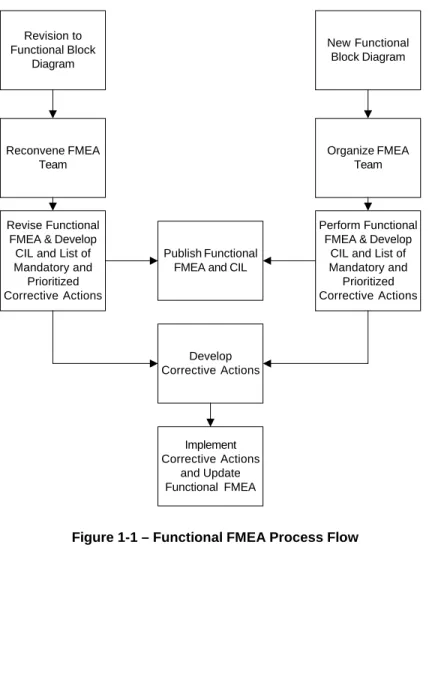
1.3.1. Process Flow. The process flow for the Functional FMEA is shown in Figure 1-1. 1.3.2. Functional FMEA Header. The header information on the Functional FMEA form (see Figure 1-2) shall be completed for each item analyzed. The top level Mission, Instrument, System, etc. name shall be entered in the header. All Team member names and functions shall be documented.
1.3.3 Subsystem/component Name. . Each item under development shall be
decomposed into its constituent subsystems components or parts. The subsystem and component or part names shall be entered in column 1 of the Functional FMEA form.
1.3.3.1. Subsystems. Each subsystem shall be identified on the Functional Block Diagram. 1.3.3.2. Components. Components shall be identified on the Functional Block Diagram. 1.3.4. Subsystem/Component Function and Performance Requirements. The function(s) of each subsystem and its performance requirements (i.e., Frequency, output power, Field of View, etc.) shall be entered in column 1 of the Functional FMEA form after the subsystem/component name.
1.3.5. Potential Failure Modes. For each Subsystem/Component Function, all Potential Failure Modes shall be postulated. The Potential Failure Modes shall be sequentially numbered and entered in column 2 of the Functional FMEA form. If provided, a Failure Mode Dictionary should be used to identify the potential failure modes. If new failure modes are identified, the Failure Mode Dictionary shall be updated. For each Potential Failure Mode, columns 2 (Potential Failure Mode), 3 (Potential Cause(s) of Failure), 4, (Occurrence) 5 (Potential Effect(s) of Failure), 6 (Severity), 7 (Severity Category), 8 (Functional/ Design Control), and 9 (Mitigation) shall be completed. Computer based forms should be used to record FMEA data.
1.3.5.1. Purchased subsystems/components. For purchased subsystems/ components, the supplier, where possible, shall supply the Potential Failure Modes and Effects Analysis. 1.3.5.2. GSFC Designed subsystems/components. For GSFC Designed
subsystems/components, the Potential Failure Modes shall be identified by the FMEA team. If Potential Failure Modes are being determined by brainstorming or team evaluation, a blackboard or computer projector display should be used to record the Potential Failure Modes until the Functional FMEA form can be properly filled out.
1.3.6. Potential Failure Causes. Potential Failure Causes are the actual failure mechanisms activated by loads applied to the system, sub system, component or part for the failure mode observed and can be a hardware, software, or operating procedure failure. When performing a Functional FMEA, it is possible to have multiple Potential Failure Causes for a Potential Failure Mode. Potential Failure Causes with a unique letter designation for each failure mode shall be entered in Column 3 of the Functional FMEA form.
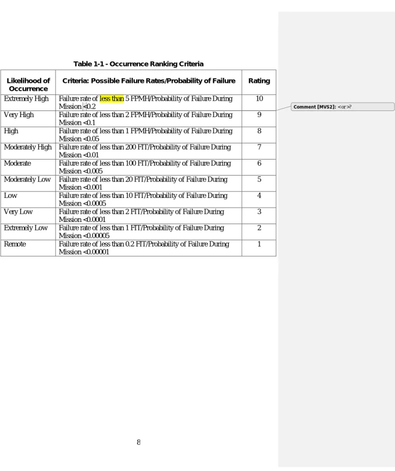
1.3.7 Occurrence. Occurrence is the relative frequency or likelihood of occurrence of the Potential Failure Cause. Table 3-1 contains the scoring for Occurrence. The Occurrence value shall be entered in column 4 of the Functional FMEA form. 1.3.8. Potential Effect(s) of Failure. Potential Failure Effects are the impact of the Potential Failure Mode on the sub-system/component (Local Effect); the system (for sub-system) or sub-system (for component) (Next Higher Level Effect); and Mission or End Item (Mission Level Effect). Person(s) operating or testing the components, sub-systems, sub-systems, End Item, or Mission may be impacted by the Failure Effect as well. For each Potential Failure Mode, one or more Potential Effects of Failure (i.e. reduction of science data, loss of mission, safety, etc.) at the Local, Next Higher, and Mission Levels shall be entered in column 5 of the Functional FMEA form.
It is possible that the Potential Failure Effect is only at the Local or Local and Next Higher Level. If that is the case, “None” should be entered as the effect at the Mission Level and/or Next Higher Level.
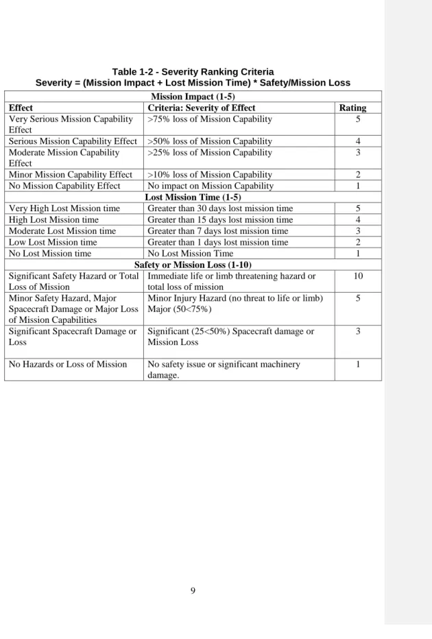
1.3.9. Severity. Each Potential Effect of Failure shall be assigned a Severity ranking. The Severity ranking shall be calculated based on the values detailed in Table 3-2. These values shall be entered in column 6 of the Functional FMEA form.
1.3.10. Mitigating Factors. For each Potential Cause of Failure, the Mitigating Factors (Functions/Designs in place to detect, prevent, or minimize the impact of the failure) shall be identified and entered in column 7 of the Functional FMEA form.
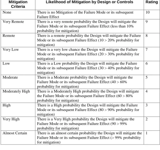
1.3.11. Mitigation. Each Mitigating Factor shall be assigned a Mitigation ranking based on the values detailed in Table 3-3. These values shall be entered in column 8 of the Functional FMEA form.
1.3.12. Risk Priority Number (RPN). The RPN shall be the product of the Occurrence, Severity, and Mitigation/Detection rankings. The RPN shall be used for application of a Pareto analysis to determine the order in which recommended actions shall be
developed to address Potential Failure Modes and Causes to improve the reliability of the equipment. The RPN is entered in column 9 of the Functional FMEA form.
1.3.13. Severity Category. The Severity Category shall be entered in column 10 of the Functional FMEA form. The criteria for Severity Category are contained in Table 1-4. 1.3.14 Critical Items List. All sub-systems/components with Potential Failure Modes with Severity Category 1, 1R, 1S, or 2 shall be placed on the Critical Items List (see Chapter 9).
1.4 Corrective Action
1.4.1. Mandatory Corrective Action. All potential failure modes in Severity Categories 1, 1R and 2 are Critical and require corrective action to reduce the Severity Category to 2R, 3 or 4. Potential Failure modes classified as 1, 1R, or 2 shall have Design FMEAs performed to ascertain the effectiveness of the Corrective Action taken. Potential failure modes classified as Severity Category 2R shall have a Design FMEA performed to ascertain the need for Corrective Action.
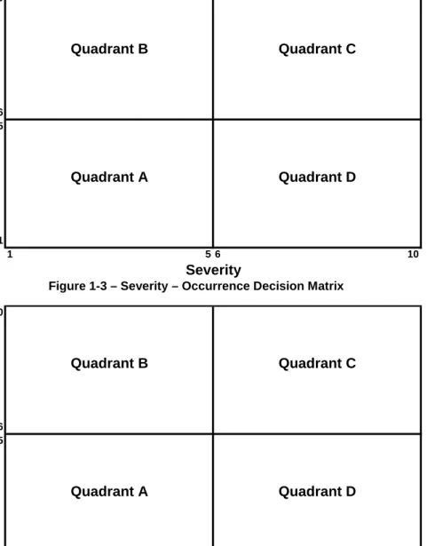
1.4.2 Recommended Action Analysis (Decision Matrices). Figures 1-3 and 1-4 are Decision Matrices for determining when a Recommended Corrective Action is required. These matrices are for potential failure modes not in Severity Categories 1, 1R, and 2. 1.4.2.1. High Priority Corrective Action. Potential failure modes that occur in Quadrant C of either matrix, and quadrant B or D of the other matrix, are high priority candidates for preventive action. Decisions to defer action must be documented in column 11 and approved by
Project/Program Management. Schedule and budget may be factors to defer action.
or D of both matrices, are medium priority candidates for preventive action. Schedule and budget may be factors to defer action.
1.4.2.3. Low Priority Corrective Action. All other potential failure modes are low priority candidates for preventive action. Where schedule and budget permit, preventive actions may be developed and implemented.
1.4.3. Recommended Actions are related to Design, Testing, and Mitigation. Recommended actions to be taken as a result of the Recommended Action Analysis (para. 1.4.2) shall be entered in column 11 of the Functional FMEA form. The intent of these actions is to reduce the values of one or more of the Occurrence, Severity, and Mitigation rankings, and thus reduce the value of the RPN as well as move the item into a lower priority quadrant. There must be an entry made in this column. If it is the determination of the FMEA Team that no action is required, "No Action Required" must be entered. "No Action Required" decisions for Mandatory Corrective actions shall not be permitted. “No Action Required” for a High Priority failure shall require Program Management and CSO approval in writing. The Recommended Actions shall be treated as Requests for Action (RFAs) by the Responsible Individual(s)/Department(s).
1.4.4. Department and/or Individual Responsible and a Completion Date . A department and/or individual responsible and a completion date shall be assigned to implement the Recommended Action(s). This information shall be entered in column 12 of the Functional FMEA form.
1.4.4. Distribution of FMEA. The FMEA shall be distributed to all members of the FMEA Team and to all Responsible Individual(s)/Department(s) who have Action Items to complete.
1.4.5. Actions Taken
1.4.5.1. The Actions Taken and the modified Severity, Occurrence, and Mitigation rankings shall be entered in columns 12 thru 15 of the Functional FMEA form.
1.4.5.2. The "Actions Taken" shall be prioritized by accomplishing the actions in order of greatest reduction in RPN.
1.4.5.3. To determine the reduction in RPN, the RPN is recalculated as if each recommended action is implemented.
1.4.5.4. The Recommended actions are classified as Mandatory, High Priority, Medium Priority, or Low Priority. The Recommended actions are then addressed within each category in order of RPN value. When a Recommended Action is not implemented, that action shall be justified and approved in writing by Program Management and the CSO.
1.4.5.5. New RPN. A new RPN shall be calculated and entered in column 17 of the Interface FMEA form for every action taken.
Table 1-1 - Occurrence Ranking Criteria Likelihood of
Occurrence
Criteria: Possible Failure Rates/Probability of Failure Rating Extremely High Failure rate of less than 5 FPMH/Probability of Failure During
Mission <0.2
10 Very High Failure rate of less than 2 FPMH/Probability of Failure During
Mission <0.1
9 High Failure rate of less than 1 FPMH/Probability of Failure During
Mission <0.05
8 Moderately High Failure rate of less than 200 FIT/Probability of Failure During
Mission <0.01
7 Moderate Failure rate of less than 100 FIT/Probability of Failure During
Mission <0.005
6 Moderately Low Failure rate of less than 20 FIT/Probability of Failure During
Mission <0.001
5 Low Failure rate of less than 10 FIT/Probability of Failure During
Mission <0.0005
4 Very Low Failure rate of less than 2 FIT/Probability of Failure During
Mission <0.0001
3 Extremely Low Failure rate of less than 1 FIT/Probability of Failure During
Mission <0.00005
2 Remote Failure rate of less than 0.2 FIT/Probability of Failure During
Mission <0.00001
1
Table 1-2 - Severity Ranking Criteria
Severity = (Mission Impact + Lost Mission Time) * Safety/Mission Loss Mission Impact (1-5)
Effect Criteria: Severity of Effect Rating
Very Serious Mission Capability Effect
>75% loss of Mission Capability 5 Serious Mission Capability Effect >50% loss of Mission Capability 4 Moderate Mission Capability
Effect
>25% loss of Mission Capability 3 Minor Mission Capability Effect >10% loss of Mission Capability 2 No Mission Capability Effect No impact on Mission Capability 1
Lost Mission Time (1-5)
Very High Lost Mission time Greater than 30 days lost mission time 5 High Lost Mission time Greater than 15 days lost mission time 4 Moderate Lost Mission time Greater than 7 days lost mission time 3 Low Lost Mission time Greater than 1 days lost mission time 2
No Lost Mission time No Lost Mission Time 1
Safety or Mission Loss (1-10) Significant Safety Hazard or Total
Loss of Mission
Immediate life or limb threatening hazard or total loss of mission
10 Minor Safety Hazard, Major
Spacecraft Damage or Major Loss of Mission Capabilities
Minor Injury Hazard (no threat to life or limb) Major (50<75%)
5
Significant Spacecraft Damage or Loss
Significant (25<50%) Spacecraft damage or Mission Loss
3
No Hazards or Loss of Mission No safety issue or significant machinery damage.
Table 1-3 - Mitigation Ranking Criteria Mitigation
Criteria
Likelihood of Mitigation by Design or Controls Rating None There is no Mitigation of the Failure Mode or its subsequent
Failure Effect
10 Very Remote There is a very remote probability the Design will mitigate the
Failure Mode or its subsequent Failure Effect (less than 10% probability for mitigation)
9
Remote There is a remote probability the Design will mitigate the Failure Mode or its subsequent Failure Effect (10 > 20% probability for mitigation)
8
Very Low There is a very low chance the Design will mitigate the Failure Mode or its subsequent Failure Effect (20 > 30% probability for mitigation)
7
Low There is a Low probability the Design will mitigate the Failure Mode or its subsequent Failure Effect (30 > 40% probability for mitigation)
6
Moderate There is a Moderate probability the Design will mitigate the Failure Mode or its subsequent Failure Effect (40 > 60% probability for mitigation)
5
Moderately High There is a Moderately High probability the Design will mitigate the Failure Mode or its subsequent Failure Effect (60 > 80% probability for mitigation)
4
High There is a High probability the Design will mitigate the Failure Mode or its subsequent Failure Effect (80 > 90% probability for mitigation)
3
Very High There is a Very High probability the Design will mitigate the Failure Mode or its subsequent Failure Effect (90 > 99% probability for mitigation)
2
Almost Certain There is an almost certain probability the Design will mitigate the Failure Mode or its subsequent Failure Effect (> 99% probability for mitigation)
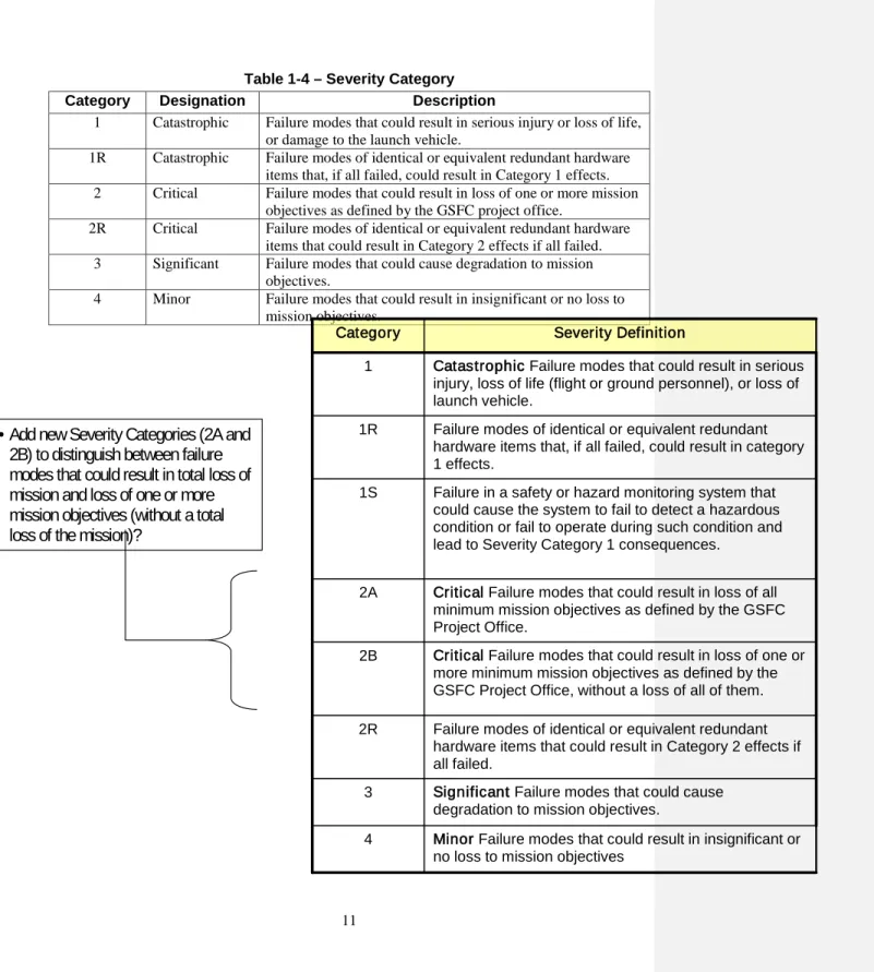
Table 1-4 – Severity Category
Category Designation Description
1 Catastrophic Failure modes that could result in serious injury or loss of life, or damage to the launch vehicle.
1R Catastrophic Failure modes of identical or equivalent redundant hardware items that, if all failed, could result in Category 1 effects. 2 Critical Failure modes that could result in loss of one or more mission
objectives as defined by the GSFC project office.
2R Critical Failure modes of identical or equivalent redundant hardware items that could result in Category 2 effects if all failed. 3 Significant Failure modes that could cause degradation to mission
objectives.
4 Minor Failure modes that could result in insignificant or no loss to mission objectives.
Minor Failure modes that could result in insignificant or no loss to mission objectives
4
Significant Failure modes that could cause degradation to mission objectives.
3
Failure modes of identical or equivalent redundant hardware items that could result in Category 2 effects if all failed.
2R
Critical Failure modes that could result in loss of one or more minimum mission objectives as defined by the GSFC Project Office, without a loss of all of them. 2B
Critical Failure modes that could result in loss of all minimum mission objectives as defined by the GSFC Project Office.
2A
Failure in a safety or hazard monitoring system that could cause the system to fail to detect a hazardous condition or fail to operate during such condition and lead to Severity Category 1 consequences.
1S
Failure modes of identical or equivalent redundant hardware items that, if all failed, could result in category 1 effects.
1R
Catastrophic Failure modes that could result in serious injury, loss of life (flight or ground personnel), or loss of launch vehicle.
1
Severity Definition Category
•
Add new Severity Categories (2A and
2B) to distinguish between failure
modes that could result in total loss of
mission and loss of one or more
mission objectives (without a total
loss of the mission)?
New Functional Block Diagram
Organize FMEA Team
Perform Functional FMEA & Develop
CIL and List of Mandatory and Prioritized Corrective Actions Develop Corrective Actions Implement Corrective Actions and Update Functional FMEA Publish Functional FMEA and CIL Revision to Functional Block Diagram Reconvene FMEA Team Revise Functional FMEA & Develop CIL and List of Mandatory and Prioritized Corrective Actions
O c c u r r e n c e S e v e r i t y M i t i g a t i o n R P N Potential Failure Modes Potential Causes of Failure O c c u r r e n c e Potential Effects of Failure Mitigating Factors
Functional Failure Modes and Effects Analysis FMEA Date:
Mission: Systems Engineer:
System: CSO: FMEA Team: Subsystem/ Component Name Action Results Actions Taken S e v e r i t y M i t i g a t i o n R P N Recommended Actions Department/ Individual Responsible & Completion Date S e v e r i t y C a t e g o r y
10 6 5 1 1 5 6 10
O
ccu
rren
ce
Severity
Quadrant B
Quadrant C
Quadrant A
Quadrant D
Figure 1-3 – Severity – Occurrence Decision Matrix
10 6 5 1 1 5 6 10
M
it
ig
a
tio
n
Severity
Quadrant B
Quadrant C
Quadrant A
Quadrant D
Chapter 2 Design FMEA 2.1 Requirements
A Functional FMEA should have been performed before the sub-system/component is submitted to a Design FMEA. A Design FMEA shall be performed when sufficient detail design information is available to identify all the constituent piece parts of the design item. In order to perform a Design FMEA, the following information, as a minimum, is required.
a) A functional block diagram of the item under development broken down to the subsystem and component level.
b) A description of each function depicted in the functional block diagram including required inputs and outputs for each block.
c) Schematics (electrical, mechanical [including thermal, fluid, mechanism]) and principles of operation for the design under analysis.
d) The manner in which each of the outputs can fail (i.e. low output, wrong frequency, incorrect motion, etc.).
e) The impact or effect of loss of each functional output depicted in the functional block diagram on the instrument, spacecraft, and/or mission. f) The compensating provisions designed into the item to mitigate the effects of
a functional output failure (i.e. redundancy, alternate operating modes, etc.). The Design FMEA shall be maintained as a living document throughout the life of a Project/Program. That is, when changes are made to the detailed design, the Design FMEA shall be updated to address these changes.
2.2 Applicability
A Design FMEAs to the constituent piece part level shall be performed for Class A missions, and all sub-systems/components having failure modes in Severity Categories 1, 1R, 2 and 2R. A Design FMEA is usually performed during Phase B of the
development process. 2.3 Methodology
If a Functional FMEA has been performed, the Design FMEA may be performed by an FMEA analyst, usually a Reliability Engineer. If a Functional FMEA has not been performed, it is highly recommended that portions of the FMEA related to Next Higher Level and Mission Effects be performed with a Team including System Engineering, Mission Operations, and Design Engineering.
are within specification and failure modes occur one at a time. (i.e. when evaluating a communications system on a spacecraft, the signals from the Earth station are assumed to be within specified limits at all times)
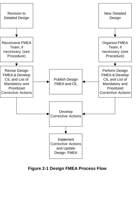
2.3.1. Process Flow. The process flow for the Design FMEA is shown in Figure 2-1. 2.3.2. Design FMEA Header. The header information on the Design FMEA form (see Figure 2-2) shall be completed for each Design analyzed. The top level Mission, Instrument, System, etc. name shall be entered in the header as well as the Design being analyzed. If a team is used for parts of the analysis, all Team member names and functions shall be documented.
2.3.3 Piece Part Name. Each design shall be broken down into its constituent piece parts. The piece part names shall be entered in column 1 of the Design FMEA form. 2.3.5. Potential Failure Modes. For each piece part, all Potential Failure Modes shall be identified. The Potential Failure Modes and shall be sequentially numbered and entered in column 2 of the Design FMEA form. If provided, a Failure Mode Dictionary shall be used to identify the potential failure modes. If new failure modes are identified, the Failure Mode Dictionary shall be updated. For each Potential Failure Mode, columns 2 (Potential Failure Mode), 3 (Potential Cause(s) of Failure), 4, (Occurrence) 5 (Potential Effect(s) of Failure), 6 (Severity), 7 (Severity Category), 8 (Functional/ Design Control), and 9 (Mitigation) shall be completed. Computer based forms should be used to record FMEA data.
2.3.5.1. Purchased piece parts. For purchased piece parts, the supplier, where possible, shall supply the Potential Failure Modes.
2.3.5.2. GSFC Designed subsystems/components. For GSFC Designed piece parts, the Potential Failure Modes shall be identified by the FMEA analyst.
2.3.5.3 Standardized Potential Failure Modes. Certain standards, handbooks, web sites and procedures such as MIL-HDBK-338, may contain piece part failure modes. The use of these failure modes is encouraged.
2.3.5.4 Indeterminate Failure Modes. In many designs it is possible for piece parts to fail in an intermediate or indeterminate state. These failure modes should be addressed in the Design FMEA, especially when there is no mitigation to deal with this type of failed state. For example, a valve that is designed to have a bipolar (open/closed) performance sticking in a half open position.
2.3.6. Potential Failure Causes. Potential Failure Causes are the actual failure mechanism for the failure mode observed under the given loading of the system or item under analysis. Failuire mechanisms and respective driving and contributing factors shall be identified. Potential Failure Causes shall be entered in Column 3 of the Design FMEA form.
the Potential Failure Cause. Table 1-1 contains the scoring for Occurrence. The Occurrence value shall be entered in column 4 of the Design FMEA form
2.3.8. Potential Effect(s) of Failure. Potential Failure Effects are the impact of the Potential Failure Mode on the component (Local Effect); the sub-system (Next Higher Level Effect); and Mission or End Item (Mission Level Effect). Person(s) operating or testing the components, sub-systems, systems, End Item, or Mission may be impacted by the Failure Effect as well. For each Potential Failure Mode, one or more Potential Effects of Failure at the Local, Next Higher and Mission Levels shall be entered in column 5 of the Design FMEA form.
It is possible that the Potential Failure Effect may be identified at the Local or Local and Next Higher Level. In these cases, “None” should be entered as the effect at the Mission Level and/or Next Higher Level.
2.3.9. Severity. Each Potential Effect of Failure shall be assigned a Severity ranking. The Severity ranking shall be calculated based on the values detailed in Table 1-2. These values shall be entered in column 6 of the Design FMEA form.
2.3.10. Mitigating Factors. For each Potential Cause of Failure, the Mitigating Factors (Functions/Designs in place to detect, prevent, or minimize the impact of the failure) shall be identified and entered in column 7 of the Design FMEA form.
2.3.11. Mitigation. Each Mitigating Factor shall be assigned a Mitigation ranking based on the values detailed in Table 1-3. These values shall be entered in column 8 of the Design FMEA form.
2.3.12. Risk Priority Number (RPN). The RPN shall be the product of the Occurrence, Severity, and Mitigation rankings. The RPN shall be used for application of a Pareto analysis to determine the order in which recommended actions shall be developed to address Potential Failure Modes and Causes to improve the reliability of the equipment. All Potential Effects of Failure shall be evaluated and analyzed. The RPN shall be entered in column 9 of the Design FMEA form.
2.3.13. Severity Category. The Severity Category shall be entered in column 10 of the Design FMEA form. The criteria for Severity Category are contained in Table 3-4. 2.3.14 Critical Items List. All designs/piece parts with Potential Failure Modes with Severity Category 1, 1R, 2, or 2R shall be placed on the Critical Items List (see Chapter 9).
2.4 Corrective Action
2.4.1. Mandatory Corrective Action. All potential failure modes in Severity Categories 1, 1R and 2 are Critical and require corrective action to reduce the Severity Category to 2R, 3 or 4.
Decision Matrices for determining when a Recommended Corrective Action is required. These matrices are for potential failure modes not in Severity Categories 1, 1R, and 2. 2.4.2.1. High Priority Corrective Action. Potential failure modes that occur in Quadrant C of either matrix, and quadrant B or D of the other matrix, are high priority candidates for preventive action. Decisions to defer action must be documented in column 11 and approved by
Project/Program Management. Schedule and budget may be factors to defer action.
2.4.2.2. Medium Priority Corrective Action. Potential failure modes that occur in Quadrants B or D of both matrices, are medium priority candidates for preventive action. Schedule and budget may be factors to defer action.
2.4.2.3. Low Priority Corrective Action. All other potential failure modes are low priority candidates for preventive action. Where schedule and budget permit, preventive actions may be developed and implemented.
2.4.3. Recommended Actions are related to Design, Testing, and Mitigation. Recommended actions to be taken as a result of the Recommended Action Analysis (para. 2.4.2) shall be entered in column 11 of the Design FMEA form. The intent of these actions is to reduce the values of one or more of the Occurrence, Severity, and Mitigation rankings, and thus reduce the value of the RPN as well as move the item into a lower priority quadrant. There must be an entry made in this column. If it is the determination of the FMEA Team that no action is required, "No Action Required" must be entered. "No Action Required" decisions for Mandatory Corrective actions shall not be permitted. “No Action Required” for a High Priority failure shall require Program Management and CSO approval in writing. The Recommended Actions shall be treated as Requests for Action (RFAs) by the Responsible Individual(s)/Department(s).
2.4.4. Department and/or Individual Responsible and a Completion Date. A department and/or individual responsible and a completion date shall be assigned to implement the Recommended Action(s). This information shall be entered in column 12 of the Design FMEA form.
2.4.5. Distribution of FMEA
2.4.5.1. The FMEA shall be distributed to all members of the FMEA Team and to all Responsible Individual(s)/Department(s) who have Action Items to complete. 2.4.6. Actions Taken
2.4.6.1. The Actions Taken and the modified Severity, Occurrence, and Mitigation rankings shall be entered in columns 12 thru 15 of the Design FMEA form.
2.4.6.2. The "Actions Taken" shall be prioritized by accomplishing the actions in order of greatest reduction in RPN.
2.4.6.3. To determine the reduction in RPN, the RPN is recalculated as if each recommended action is implemented.
2.4.6.4. The Recommended actions are classified as Mandatory, High Priority, Medium Priority, or Low Priority. The Recommended actions are then addressed within each category in order of RPN value. When a Recommended Action is not implemented, that action shall be justified and approved in writing by Program Management and the CSO.
2.4.6.5. New RPN. A new RPN shall be calculated and entered in column 17 of the Interface FMEA form for every action taken.
Note should be added that document controls need to be in place to insure that proper version is available for inspection and is updated with available data. Do we have a procedure for this?
New Detailed Design Organize FMEA Team, if necessary (see Procedure) Perform Design FMEA & Develop
CIL and List of Mandatory and Prioritized Corrective Actions Develop Corrective Actions Implement Corrective Actions and Update Design FMEA Publish Design FMEA and CIL Revision to Detailed Design Reconvene FMEA Team, if necessary (see Procedure) Revise Design FMEA & Develop
CIL and List of Mandatory and Prioritized Corrective Actions
O c c u r r e n c e S e v e r i t y M i t i g a t i o n R P N
Component Design Engineer
FMEA Team:
Piece Part Name
Action Results Potential Failure Modes Potential Causes of Failure O c c u r r e n c e Potential Effects of Failure
Design Failure Modes and Effects Analysis FMEA Date:
Mission: Systems Engineer:
System: CSO: Actions Taken S e v e r i t y M i t i g a t i o n R P N Recommended Actions Department/ Individual Responsible & Completion Date S e v e r i t y C a t e g o r y Mitigating Factors
Figure 2-2 - Design FMEA Form Comment [TJD3]: Just a thought, consider
Chapter 3 Interface FMEA 3.1 Requirements
An Interface FMEA shall be performed when sufficient design information is available to define the functional interface between components and/or sub-systems to the first active component on either side of the interface. In order to perform a Interface FMEA, the following information, as a minimum, is required.
a) A functional block diagram of the item under development broken down to the subsystem and component level.
b) A description of each function depicted in the functional block diagram including required inputs and outputs for each block.
c) The detail design of the components/sub-systems on either side of the interface sufficient to identify the first active component on either side of the interface.
d) The manner in which each of the required outputs can fail (i.e. low output, wrong frequency, incorrect motion, etc.).
e) The impact or effect of loss of each functional interface depicted in the functional block diagram and detail design on the instrument, spacecraft, and/or mission.
f) The compensating provisions designed into the item to mitigate the effects of a functional output failure (i.e. redundancy, alternate operating modes, etc.). The Interface FMEA shall be maintained as a living document throughout the life of a Project/Program. That is, when changes are made to the interface design, the Interface FMEA shall be updated to address these changes.
3.2 Applicability
An Interface FMEA is performed for every interface between sub-systems and between instrument(s) and spacecraft and between instruments during Phase B of the
development process. 3.3 Methodology
If a Functional FMEA has been performed, the Interface FMEA may be performed by an FMEA analyst, usually a Reliability Engineer. If a Functional FMEA has not been performed, it is highly recommended that portions of the FMEA related to Next Higher Level and Mission Effects be performed with a Team including System Engineering, Mission Operations, and Design Engineering.
interface under analysis are within specification and failure modes occur one at a time. (i.e. when evaluating a communications system on a spacecraft, the signals from the Earth station are assumed to be within specified limits at all times)
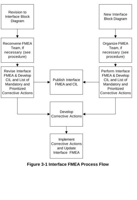
3.3.1. Process Flow. The process flow for the Interface FMEA is shown in Figure 3-1. 3.3.2. Interface FMEA Header. The header information on the Interface FMEA form (see Figure 3-2) shall be completed for each Interface analyzed. The top level Mission, Instrument, System, etc. name shall be entered in the header. If a team was used for part of the analysis, all Team member names and functions shall be documented. 3.3.3 Interface Signal Name. Each interface under development shall be broken down into its constituent signals. The signal names shall be entered in column 1 of the Interface FMEA form.
3.3.4. Signal Function and Performance Requirements. The function of each signal and its performance requirements (i.e., Frequency, output power, impedance, etc.) shall be entered in column 1 of the Interface FMEA form after the Signal Function name. 3.3.5. Potential Failure Modes. For each Signal Function, all Potential Failure Modes shall be identified. The Potential Failure Modes shall be entered in column 2 of the Interface FMEA form. If provided, a Failure Mode Dictionary shall be used to identify the potential failure modes. If new failure modes are identified, the Failure Mode Dictionary shall be updated. For each Potential Failure Mode, columns 2 (Potential Failure Mode), 3 (Potential Cause(s) of Failure), 4, (Occurrence) 5 (Potential Effect(s) of Failure), 6 (Severity), 7 (Severity Category), 8 (Functional/ Design Control), and 9 (Mitigation) shall be completed. Computer based forms should be used to record FMEA data.
3.3.5.1. Purchased subsystems/components. For purchased subsystems/ components, the supplier, where possible, shall supply the Potential Failure Modes.
3.3.5.2. GSFC Designed subsystems/components. For GSFC Designed
subsystems/components, the Potential Failure Modes shall be identified by the FMEA team. If Potential Failure Modes are being determined by brainstorming or team evaluation, a blackboard or computer projector display should be used to record the Potential Failure Modes until the Functional FMEA form can be properly filled out.
3.3.6. Potential Failure Causes. Potential Failure Causes are the actual failure mechanism for the failure mode observed and can be a hardware or software failure. When performing an Interface FMEA, it is possible to have multiple Potential Failure Causes for a Potential Failure Mode. Potential Failure Causes shall be entered in Column 3 of the Interface FMEA form.
3.3.7 Occurrence. Occurrence is the relative frequency or likelihood of occurrence of the Potential Failure Cause. Table 1-1 contains the scoring for Occurrence. The Occurrence value shall be entered in column 4 of the Interface FMEA form
Potential Failure Mode on the interface (Local Effect); the system Next Higher Level Effect); and Mission or End Item (Mission Level Effect). Person(s) operating or testing the components, sub-systems, systems. For each Potential Failure Mode, one or more Local, Next Higher and Mission Level Potential Effects of Failure (i.e. reduction of science data, loss of mission, safety, etc.) shall be entered in column 5 of the Interface FMEA form.
It is possible that the Potential Failure Effect is only at the Local or Local and Next Higher Level. If that is the case, “None” should be entered as the effect at the Mission Level and/or Next Higher Level.
3.3.9. Severity. Each Potential Effect of Failure shall be assigned a Severity ranking. The Severity ranking shall be calculated based on the values detailed in Table 1-2. These values shall be entered in column 6 of the Interface FMEA form.
3.3.10. Mitigating Factors. For each Potential Cause of Failure, the Mitigating Factors (Functions/Designs in place to detect, prevent, or minimize the impact of the failure) shall be identified and shall be entered in column 7 of the Interface FMEA form. 3.3.11. Mitigation. Each Mitigating Factor shall be assigned a Mitigation ranking based on the values detailed in Table 1-3. These values shall be entered in column 8 of the Interface FMEA form.
3.3.12. Risk Priority Number (RPN). The RPN shall be the product of the Occurrence, Severity, and Mitigation rankings. The RPN shall be used for application of a Pareto analysis to determine the order in which recommended actions shall be developed to address Potential Failure Modes and Causes to improve the reliability of the equipment. All Potential Effects of Failure shall be evaluated and analyzed. The RPN is entered in column 9 of the Interface FMEA form.
3.3.13. Severity Category. The Severity Category shall be entered in column 10 of the Interface FMEA form. The criteria for Severity Category are contained in Table 3-4. 3.4 Corrective Action
3.4.1. Mandatory Corrective Action. All potential failure modes in Severity Categories 1, 1R and 2 are Critical and require corrective action to reduce the Severity Category to 2R, 3 or 4.
3.4.2 Recommended Action Analysis (Decision Matrices). Figures 1-3 and 1-4 are Decision Matrices for determining when a Recommended Corrective Action is required. These matrices are for potential failure modes not in Severity Categories 1, 1R, and 2. 3.4.2.1. High Priority Corrective Action. Potential failure modes that occur in Quadrant C of either matrix, and quadrant B or D of the other matrix, are high priority candidates for preventive action. Decisions to defer action must be documented in column 11 and approved by
3.4.2.2. Medium Priority Corrective Action. Potential failure modes that occur in Quadrants B or D of both matrices, are medium priority candidates for preventive action. Schedule and budget may be factors to defer action.
3.4.2.3. Low Priority Corrective Action. All other potential failure modes are low priority candidates for preventive action. Where schedule and budget permit, preventive actions may be developed and implemented.
3.4.3. Recommended Actions are related to Design, Testing, and Mitigation. Recommended actions to be taken as a result of the Recommended Action Analysis (para. 3.4.2) shall be entered in column 11 of the Interface FMEA form. The intent of these actions is to reduce the values of one or more of the Occurrence, Severity, and Mitigation rankings, and thus reduce the value of the RPN as well as move the item into a lower priority quadrant. There must be an entry made in this column. If it is the determination of the FMEA Team that no action is required, "No Action Required" must be entered. "No Action Required" decisions for Mandatory Corrective actions shall not be permitted. “No Action Required” for a High Priority failure shall require Program Management and CSO approval in writing. The Recommended Actions shall be treated as Requests for Action (RFAs) by the Responsible Individual(s)/Department(s).
3.4.4. Department and/or Individual Responsible and a Completion Date . A department and/or individual responsible and a completion date shall be assigned to implement the Recommended Action(s). This information shall be entered in column 12 of the Interface FMEA form.
3.4.4. Distribution of FMEA
3.4.4.1. The FMEA shall be distributed to all members of the FMEA Team and to all Responsible Individual(s)/Department(s) who have Action Items to complete. 3.4.5. Actions Taken
3.4.5.1. The Actions Taken and the modified Severity, Occurrence, and Mitigation rankings shall be entered in columns 12 thru 15 of the Interface FMEA form.
3.4.5.2. The "Actions Taken" shall be prioritized by accomplishing the actions in order of greatest reduction in RPN.
3.4.5.3. To determine the reduction in RPN, the RPN is recalculated as if each recommended action is implemented.
3.4.5.4. The Recommended actions are classified as Mandatory, High Priority, Medium Priority, or Low Priority. The Recommended actions are then addressed within each category in order of RPN value. When a Recommended Action is not implemented, that action shall be justified and approved in writing by Program Management and the CSO.
3.4.5.5. New RPN. A new RPN shall be calculated and entered in column 17 of the Interface FMEA form for every action taken.
New Interface Block Diagram Organize FMEA Team, if necessary (see procedure) Perform Interface FMEA & Develop CIL and List of Mandatory and Prioritized Corrective Actions Develop Corrective Actions Implement Corrective Actions and Update Interface FMEA Publish Interface FMEA and CIL Revision to Interface Block Diagram Reconvene FMEA Team, If necessary (see procedure) Revise Interface FMEA & Develop CIL and List of Mandatory and Prioritized Corrective Actions
O c c u r r e n c e S e v e r i t y M i t i g a t i o n R P N CSO: Actions Taken S e v e r i t y M i t i g a t i o n R P N Recommended Actions Department/ Individual Responsible & Completion Date S e v e r i t y C a t e g o r y Mitigating Factors
Interface Failure Modes and Effects Analysis FMEA Date:
Mission: Systems Engineer:
Interface: Design Engineer
FMEA Team: Interface Signal Name Action Results Potential Failure Modes Potential Causes of Failure O c c u r r e n c e Potential Effects of Failure System:
Chapter 4 Software FMEA 4.1 Requirements
A Software FMEA shall be performed as soon as sufficient information is available to construct a flow chart of the software under development. In order to perform a Software FMEA, the following information, as a minimum, is required.
a) A functional block diagram of the item under development broken down to the subsystem and component level.
b) A detailed flow chart of the Software under Development.
c) A description of each function depicted in the functional block diagram including required inputs and outputs for each block.
d) A description of each functional block in the software flow chart.
e) A description of how the Software Flow Chart and Functional Block Diagram interface and interact.
f) The manner in which each of the required software functions can fail (i.e. fails to turn on function x, fails to read temperature sensor, etc.).
g) The impact or effect of loss of each functional software block depicted in the software flow chart on the instrument, spacecraft, and/or mission. (the impacts or effects may be developed during a team approach to performing the Software FMEA)
h) The compensating provisions designed into the item to mitigate the effects of a functional software block failure (i.e. redundancy, alternate operating modes, etc.).
A code line by code line FMEA may be necessary for software modules that perform critical functions. In that case, each line of code shall have sufficient annotated
description to facilitate a productive FMEA. Where “software functional block” is used in this procedure, “software line of code” shall be substituted.
The Software FMEA shall be maintained as a living document throughout the life of a Project/Program. That is, when changes are made to the software flow chart, the Software FMEA shall be updated to address these changes.
4.2 Applicability
A Software FMEA is performed for every Mission, Spacecraft, Instrument, Ground System, systems, sub-systems, software and component during Phase B of the
development process. 4.3 Methodology
The Software FMEA shall whenever possible be performed by an FMEA Team consisting of a Reliability Engineer, Systems Engineer, Software Engineer, Electrical Engineer, I&T Engineer, and Mission Operations Engineer.
4.3.1. Process Flow. The process flow for the Software FMEA is shown in Figure 3-1. 4.3.2. Software FMEA Header. The header information on the Software FMEA form (see Figure 4-2) shall be completed for each Software Flow Chart analyzed. The top level Mission, Instrument, System, etc. name shall be entered in the header. All Team member names and functions shall be documented.
4.3.3 Software Functional Block Name. Each software module under development shall be broken down into its constituent software functional blocks. The subsystem and component names shall be entered in column 1 of the Software FMEA form.
4.3.4. Software Functional Block Requirements. The requirements for each software functional block shall be entered in column 1 of the Functional FMEA form after the Software Functional Block Name.
4.3.5. Potential Failure Modes. For each Software Functional Block, all Potential Failure Modes shall be identified. The Potential Failure Modes shall be entered in column 2 of the Software FMEA form. If provided, a Failure Mode Dictionary shall be used to identify the potential failure modes. If new failure modes are identified, the Failure Mode Dictionary shall be updated. For each Potential Failure Mode, columns 2 (Potential Failure Mode), 3 (Potential Cause(s) of Failure), 4, (Occurrence) 5 (Potential Effect(s) of Failure), 6 (Severity), 7 (Severity Category), 8 (Functional/ Design Control), and 9 (Mitigation) shall be completed. Computer based forms should be used to record FMEA data.
4.3.6. Potential Failure Causes. Potential Failure Causes are the actual software faults for the failure mode that can be observed and can be a hardware to software compatibility, software coding, or operating procedure failure. When performing a Software FMEA, it is possible to have multiple Software faults for a Potential Failure Mode. Potential Failure Causes are entered in Column 3 of the softwarel FMEA form. 4.3.7 Occurrence. Occurrence is the likelihood of the Potential Failure Cause occurring. Table 1-1 contains the scoring for Occurrence. The Occurrence value is entered in column 4 of the Software FMEA form
4.3.8. Potential Effect(s) of Failure. Potential Failure Effects are the impact of the Potential Failure Mode on the sub-system/component (Local Effect); the system (for sub-system) or sub-system (for component) (Next Higher Level Effect); and Mission or End Item (Mission Level Effect). Person(s) operating or testing the components, sub-systems, sub-systems, End Item, or Mission may be impacted by the Failure Effect as well.
For each Potential Failure Mode, one or more Potential Effects of Failure (i.e. reduction of science data, loss of mission, safety, etc.) shall be entered in column 5 of the Software FMEA form.
It is possible that the Potential Failure Effect is only at the Local or Local and Next Higher Level. If that is the case, “None” should be entered as the effect at the Mission Level and/or Next Higher Level.
4.3.9. Severity. Each Potential Effect of Failure shall be assigned a Severity ranking. The Severity ranking shall be calculated based on the values detailed in Table 1-2. These values shall be entered in column 6 of the Software FMEA form.
4.3.10. Mitigating Factors. For each Potential Cause of Failure, the Mitigating Factors (Functions/Designs in place to detect, prevent, or minimize the impact of the failure) shall be identified and entered in column 7 of the Software FMEA form.
4.3.11. Mitigation. Each Mitigating Factor shall be assigned a Mitigation ranking based on the values detailed in Table 1-3. These values shall be entered in column 8 of the Software FMEA form.
4.3.12. Risk Priority Number (RPN). The RPN shall be the product of the Occurrence, Severity, and Mitigation rankings. The RPN shall be used for application of a Pareto analysis to determine the order in which recommended actions shall be developed to address Potential Failure Modes and Causes to improve the reliability of the equipment. All Potential Effects of Failure shall be evaluated and analyzed. The RPN is entered in column 9 of the Software FMEA form.
4.3.13. Severity Category. The Severity Category shall be entered in column 10 of the Software FMEA form. The criteria for Severity Category are contained in Table 1-4. 4.4 Corrective Action
4.4.1. Mandatory Corrective Action. All potential failure modes in Severity Categories 1, 1R and 2 are Critical and require corrective action to reduce the Severity Category to 2R, 3 or 4.
4.4.2 Recommended Action Analysis (Decision Matrices). Figures 1-3 and 1-4 are Decision Matrices for determining when a Recommended Corrective Action is required. These matrices are for potential failure modes not in Severity Categories 1, 1R, and 2. 4.4.2.1. High Priority Corrective Action. Potential failure modes that occur in Quadrant C of either matrix, and quadrant B or D of the other matrix, are high priority candidates for preventive action. Decisions to defer action must be documented in column 11 and approved by
Project/Program Management. Schedule and budget may be factors to defer action.
4.4.2.2. Medium Priority Corrective Action. Potential failure modes that occur in Quadrants B or D of both matrices, are medium priority candidates for preventive action. Schedule and budget may be factors to defer action.
4.4.2.3. Low Priority Corrective Action. All other potential failure modes are low priority candidates for preventive action. Where schedule and budget permit, preventive actions may be developed and implemented.
4.4.3. Recommended Actions are related to Design, Testing, and Mitigation. Recommended actions to be taken as a result of the Recommended Action Analysis (para. 4.4.2) shall be entered in column 11 of the Software FMEA form. The intent of these actions is to reduce the values of one or more of the Occurrence, Severity, and Mitigation rankings, and thus reduce the value of the RPN as well as move the item into a lower priority quadrant. There must be an entry made in this column. If it is the determination of the FMEA Team that no action is required, "No Action Required" must be entered. "No Action Required" decisions for Mandatory Corrective actions shall not be permitted. “No Action Required” for a High Priority failure shall require Program Management and CSO approval in writing. The Recommended Actions shall be treated as Requests for Action (RFAs) by the Responsible Individual(s)/Department(s).
4.4.4. Department and/or Individual Responsible and a Completion Date. A department and/or individual responsible and a completion date shall be assigned to implement the Recommended Action(s). This information shall be entered in column 12 of the Software FMEA form.
4.4.5. Distribution of FMEA
4.4.5.1. The FMEA shall be distributed to all members of the FMEA Team and to all Responsible Individual(s)/Department(s) who have Action Items to complete. 4.4.6. Actions Taken
4.4.6.1. The Actions Taken and the modified Severity, Occurrence, and Mitigation rankings shall be entered in columns 12 thru 15 of the Software FMEA form.
4.4.6.2. The "Actions Taken" shall be prioritized by accomplishing the actions in order of greatest reduction in RPN.
4.4.6.3. To determine the reduction in RPN, the RPN is recalculated as if each recommended action is implemented.
4.4.6.4. The Recommended actions are classified as Mandatory, High Priority, Medium Priority, or Low Priority. The Recommended actions are then addressed within each category in order of RPN value. When a Recommended Action is not implemented, that action shall be justified and approved in writing by Program Management and the CSO.
4.4.6.5. New RPN. A new RPN shall be calculated and entered in column 17 of the Software FMEA form for every action taken.
New Software Flow Chart
Organize FMEA Team
Perform Software FMEA & Develop
CIL and List of Mandatory and Prioritized Corrective Actions Develop Corrective Actions Implement Corrective Actions and Update Software FMEA Publish Software FMEA and CIL Revision to Software Flow Chart Reconvene FMEA Team Revise Software FMEA & Develop CIL and List of Mandatory and Prioritized Corrective Actions
O c c u r r e n c e S e v e r i t y M i t i g a t i o n R P N Software Module: Design Engineer
FMEA Team: Software Functional Block Name Action Results Potential Failure Modes Potential Causes of Failure O c c u r r e n c e Potential Effects of Failure
Software Failure Modes and Effects Analysis FMEA Date:
Mission: Systems Engineer:
System: CSO: Actions Taken S e v e r i t y M i t i g a t i o n R P N Recommended Actions Department/ Individual Responsible & Completion Date S e v e r i t y C a t e g o r y Mitigating Factors
Chapter 5 Ground Support Equipment (GSE) FMEA 5.1 Requirements
A GSE FMEA shall be performed as soon as sufficient information is available to define the GSE and the interface to the item under development. In order to perform a GSE FMEA, the following information, as a minimum, is required.
a) Functional block diagrams of the item under development and GSE broken down to the subsystem and component level.
b) A description of each function depicted in the functional block diagrams including required inputs and outputs for each block.
c) The detailed design description of the interface between GSE and the item under development including the manner in which each of the interfaced circuits, fluid systems, or mechanisms between the Item under development and GSE can fail (i.e. low output, wrong frequency, incorrect motion, etc.). d) The compensating provisions designed into the GSE and item under
development to protect the item under development from the effects of an interface failure.
The GSE FMEA shall be maintained as a living document throughout the life of a Project/Program. That is, when changes are made to the GSE and/or Item under development, the GSE FMEA shall be updated to address these changes. 5.2 Applicability
A GSE FMEA is performed for every item of flight hardware that will undergo test using either custom or off the shelf GSE prior to the Integration and Test (I&T) phase of the Project/Program.
5.3 Methodology
The GSE FMEA shall whenever possible be performed by an FMEA Team consisting of a Reliability Engineer, Systems Engineer, Electrical Engineer, Mechanical Engineer, and I&T Engineer.
5.3.1. Process Flow. The process flow for the GSE FMEA is shown in Figure 5-1. 5.3.2. GSE FMEA Header. The header information on the GSE FMEA form (see Figure 5-2) shall be completed for each GSE/Item under Development Interface analyzed. The top level Mission, Program, or Project. name shall be entered in the header. All Team member names and functions shall be documented.
5.3.3 GSE Functional Block Name. Each GSE/Item under development Interface shall be broken down into its constituent functional blocks. The GSE Functional Block names shall be entered in column 1 of the GSE FMEA form.
5.3.4. GSE Functional Block Function and Performance Requirements. The function of each GSE Functional Block and its performance requirements (i.e., Frequency, output power, Field of View, etc.) shall be entered in column 1 of the GSE FMEA form after the GSE Functional Block name.
5.3.5. Potential Failure Modes. For each GSE Functional Block, all Potential Failure Modes shall be identified. The Potential Failure Modes shall be entered in column 2 of the GSE FMEA form. If provided, a Failure Mode Dictionary shall be used to identify the potential failure modes. If new failure modes are identified, the Failure Mode Dictionary shall be updated. For each Potential Failure Mode, columns 2 (Potential Failure Mode), 3 (Potential Cause(s) of Failure), 4, (Occurrence) 5 (Potential Effect(s) of Failure), 6 (Severity), 7 (Severity Category), 8 (Mitigating Factors), and 9 (Mitigation) shall be completed. Computer based forms should be used to record FMEA data.
5.3.5.1. Purchased GSE. For purchased GSE, the supplier, where possible, shall supply the Potential Failure Modes.
5.3.5.2. GSFC Designed GSE. For GSFC Designed GSE, the Potential Failure Modes shall be identified by the FMEA team.
5.3.6. Potential Failure Causes. Potential Failure Causes are the actual failure mechanism for the failure mode observed and can be a hardware, software, or operating procedure failure. When performing a GSE FMEA, it is possible to have multiple Potential Failure Causes for a Potential Failure Mode. Potential Failure Causes are entered in Column 3 of the GSE FMEA form.
5.3.7 Occurrence. Occurrence is the relative frequency or likelihood of occurrence of the Potential Failure Cause. Table 1-1 contains the scoring for Occurrence. The Occurrence value is entered in column 4 of the GSE FMEA form
5.3.8. Potential Effect(s) of Failure. Potential Failure Effects are the impact of the Potential Failure Mode on the sub-system/component (Local Effect); the system (for sub-system) or sub-system (for component) (Next Higher Level Effect); and Mission or End Item (Mission Level Effect). Person(s) operating or testing the components, sub-systems, sub-systems, End Item, or Mission may be impacted by the Failure Effect as well. For each Potential Failure Mode, one or more Potential Effects of Failure (i.e. loss of component, loss of system, etc.) shall be entered in column 5 of the GSE FMEA form. It is possible that the Potential Failure Effect is only at the Local or Local and Next Higher Level. If that is the case, “None” should be entered as the effect at the Mission Level and/or Next Higher Level.
5.3.9. Severity. Each Potential Effect of Failure shall be assigned a Severity ranking. The Severity ranking shall be calculated based on the values detailed in Table 5-2.
![Figure 2-2 - Design FMEA Form Comment [TJD3]: Just a thought, consider adding a verification colum?](https://thumb-us.123doks.com/thumbv2/123dok_us/10101501.2910631/21.1188.55.1088.180.670/figure-design-fmea-comment-thought-consider-adding-verification.webp)