STATIC
TRANSFER
SWITCHES
Static Transfer Switch SSTN400AC400
The quality system has an ISO9001:2000 certificate, which covers research and development, design, production and servicing of industrial electronic products. 2002: Gold Medal at the 74th Poznań International
Fair for the Static Transfer Switches series SS, SSN, SST, SSTN.
APPLICATION
Static Transfer Switches (STS) are designed to transfer supply between independent one-phase or three-phase AC power sources. Unlike traditional automatic transfer switches (ATS), STS provides 20 times faster load trans-fer (typically 1/4 of a cycle), which ensures the uninter-rupted operation of even the most sensitive electronic equipment. Load retransfer to a preferred input source is virtually instantaneous (typically 100 µs). The basic appli-cations of STS are in automatic systems for power indus-try, power supply systems for petrochemical indusindus-try, computer and telecommunication centres, operating the-atres, intensive care units, automatic and security systems of 'intelligent' buildings as well as other equipment which is highly sensitive on supply interruption.
It's high overload capacity and transfer algorithm enables rapid fuse blow during short-circuits. In consequence volt-age immediately returns to normal value to supply other loads. The built-in transient voltage surge suppression system for SCR switches provides additional protection against damage to supplied devices.
STANDARD FEATURES
Ability to create systems with redundancy (switching be-tween independent electrical supply lines, various UPS devices and generators)
Short transfer time (typically 3 ms after line failure) Elimination of voltage swells, sags and interruptions on
loads (switch-over)
Protection against voltage variations out off range Switches are controlled by Fail-Safe CMOS Logic Internal redundancy for power supply systems and SCR drivers (eliminating failures in single points) Easy to operate
Easy to install
Lowest MTTR (mean time to repair) Low installation and maintenance costs
Bypass switches to provide continuous non-break oper-ation during STS maintenance
Remote switching of power sources Status indication for power supply system
and STS
Options
RS485 communications interface Measurements in A, V, kW and kVar
K5 normaly ON U1 O2 K4 normaly ON K3 normaly ON LINE A L1 CT1 K2 normaly OFF O3 LINE B L2 K1 normaly OFF O1 U2 OUTPUT STS
Fig. 1. Single line diagram of STS with maintenance bypasses.
SS 1-phase 1-pole static transfer switch SSN 1-phase 2-poles static transfer switch SST 3-phases 3-poles static transfer switch SSTN 3-phases 4-poles static transfer switch DEVICE NAME
STANDARDS APPLIED
Standards Description
European standards
EN 50178 Electronic Equipment for Use in Power Installations. IEC 60146-1-2 General Requirements and Line Commutated Converters. IEC 60529 Degrees of Protection Provided by Enclosures (IP Code). EN 50091-2 Electromagnetic Compatibility Requirements.
EN 55022 Limits and methods of radio disturbanse charakteristics of information technology equipment (CISPR 22:1993).
EN 60555-2 Disturbances in supply systems caused by household appliances and similar electrical equipment- Part 2: Harmonics.
EN 60555-3 Disturbances in supply systems caused by household appliances and similar electrical equipment- Part 3: Voltage fluctuations.
PN-IEC 146-5 Switches for Uninterrupted Power Systems. Canadian standards, C22.2 Series
0-M1991 (R1997) General Requirements Can. El. Code P.II. 0.4-M1982 (R1993) Bonding and Grounding of Electrical Equipment. 0.12-M1985 (R1992) Wiring Space and Wire Bending Space.
14-1995 Industrial Control Equipment.
107.1-95 Commercial and Industrial Power Supply Equipment. CSA Publication SPE-1000-94 Model Code for the Field Evaluation of Electrical Equipment.
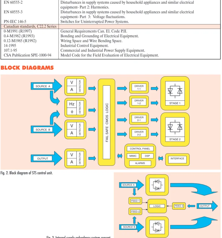
SOURCE A SOURCE B LOGIC FEED 1 FEED 2 FEED 3 OUTPUT DRIVER 1-1 DRIVER 1-2 DRIVER 2-1 DRIVER 2-2 STAGE 1 STAGE 2 Hz DET E CT OR φ V DET E CT OR A V DET E CT OR A FA IL SA FE C M OS LOGIC V DET E CT OR A MIMIC DSP CONTROL PANEL ALARMS INTERFACE SOURCE A OUTPUT SOURCE B
Fig. 2. Block diagram of STS control unit.
Fig. 3. Internal supply redundancy system concept.
XO2:N O21 SECONDARY SOURCE PRIMARY SOURCE SECONDARY SOURCE SECONDARY
SOURCE PRIMARYSOURCE PRIMARY SOURCE K1:1 K3:1 K4:1 U11 XO1:PE O10 U21 STS OUTPUT STS OUTPUT STS OUTPUT O31 XO2:PE K2:1 XO1:L1 XO3:PE XO3:N L21 XO3:L1 O11 XO1:N CT1 L11 XO2:L1 K5:1
Fig. 4. Power stage circuit of 1-phase 1-pole switch SS.
K2:0 O20
SECONDARY
SOURCE SECONDARYSOURCE SECONDARYSOURCE
K3:1 U10
PRIMARY
SOURCE PRIMARYSOURCE PRIMARYSOURCE
L11 U21 XO3:L1 XO2:PE L20 L21 K1:0 U20 K4:0 XO2:N XO2:L1 K5:1 XO3:PE XO3:N K4:1 XO1:PE K1:1 STS OUTPUT STS OUTPUT STS OUTPUT O10 L10 XO1:N O30 K2:1 O31 U11 K3:0 K5:0 O11 XO1:L1 CT1 O21
Fig. 5. Power stage circuit of 1-phase 2-poles switch SSN.
L23 XO3:L1 L12 O11 K4:1 K4:3 K3:2 L21 XO2:N XO3:L2 XO2:L3 O22 K1:3 U13 XO3:L3 XO1:L3 XO1:N O13 CT2 O21 XO1:L2 O31 U11 CT1 U21 O23 L22 XO3:PE STS OUTPUT
STS OUTPUT STS OUTPUT STS OUTPUT STS OUTPUT
K3:1 K5:3 XO3:N XO2:L1 K3:3 O10 XO1:L1 SECONDARY SOURCE O12 K4:2 K2:3 U23 L13 PRIMARY
SOURCE PRIMARYSOURCE SOURCESECONDARY PRIMARYSOURCE SOURCESECONDARY PRIMARYSOURCE SECOSOURCENDARY PRIMARYSOURCE SECOSOURCENDARY
K1:1 XO2:L2 O33 K2:1 O32 K5:2 K1:2 L11 U12 XO1:PE CT3 K5:1 U22 XO2:PE K2:2
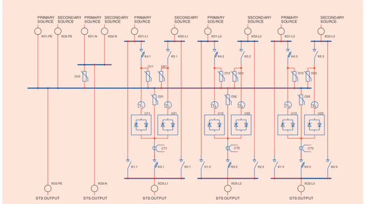
Fig. 6. Power stage circuit of 3-phases 3-poles switch SST.
L23 K4:1 CT2 XO2:PE K1:1 K2:0 O10 K4:0 XO3:L1 O13 O23 CT1 XO2:N U22 L22 O20 CT3 K3:2 O33 U11 XO3:PE
STS OUTPUT STS OUTPUT STS OUTPUT STS OUTPUT STS OUTPUT
K2:1 K4:3 U10 PRIMARY SOURCE K2:2 XO3:L2 O21 O11 O32 K2:3 K1:0 K5:1 U20 XO1:L1 L10 XO2:L1 L21 XO1:PE L20 XO1:L3 O12 K5:2 XO2:L3 U23 XO1:N O31 U13 XO1:L2 K1:2 XO3:L3 O30 K5:3 K3:1 K3:3 L13 XO3:N XO2:L2 U12 K4:2 U21 K5:0 L11 SECONDARY SOURCE PRIMARYSOURCE
SECONDARY
SOURCE PRIMARYSOURCE
SECONDARY
SOURCE PRIMARYSOURCE
SECONDARY
SOURCE PRIMARYSOURCE
SECONDARY SOURCE K1:3 L12 K3:0 O22
PRINCIPLE OF OPERATION
The SS (1-phase 1-pole) Static Transfer Switch consists of two bidirectional thyristor switches equipped with control and protection system. The SSN (1-phase 2-poles) switch has an additional neutral line switch. Control system is based on the fail-safe CMOS logic. Input source and out-put line are protected by transient voltage surge suppres-sion varistors.
After failure of preferred source, STS checks the state of the alternate power source and transfers load to the source that provides better quality power.
Many modes of operation and many additional settings are provided to meet site-specific requirements.
Transfer may be triggered by:
Disturbance of preferred source voltage Overcurrent in source
Manual change of preferred source Remote change of preferred source
Transfer is not allowed in the event of:
Incorrect voltage in the alternate source
Excess output current (in load dedicated STS installa-tion)
Transfer is delayed in the event of:
No synchronization between preferred and alternate source
Exceeding of the phase shift limit between the two sources.
With both sources correct and synchronised (phase error within the acceptable range), manual or remote transfer is performed in less than 200 µs. Transfers initiated by fault conditions on the preferred source depend on the status of the alternate source. For synchronised power sources with phase error within the limits, switching to an alternate source is obtained within 6 ms delay. Lack of synchronisation causes delay before transfer. It is pos-sible to set delay time with dipswitches (11 ms, 15 ms, 23 ms or 48 ms). Total transfer time is equal to the sum of 2 ms detection time and the alternate source thyristor delay time (so 13, 17, 25 or 50 ms respectively).
The SST (3-phases 3-poles) Static Transfer Switch con-sists of a set of three 1-phase switches. The SSTN (3-phases 4-poles) Switch has an additional neutral line switch. For both switches, load capacity of neutral line is rated to 200% of phase line load capacity.
Internal mechanical bypasses enable correct servicing. Transfer for maintenance mode is performed without in-terrupting the load with delay (less than 200 µs). As an
option, a maintenance bypass may be equipped with me-chanical interlocks to avoid short circuit during manipu-lation.
Internal redundancy for power supply systems and for cooling systems, with internal system monitoring ensure extremely high reliability of the STS.
DESIGN
PRIMARY SOURCE 3x400V 50Hz
RETRANSFER OFF COMM COMM COMM PRIMARY LINE ON NO NO NC SCR_board SSTN400AC63scr X10:1 X10:2 X10:3 X10:4 X10:5 X10:6 X10:7 X10:8 X10:9 X10:10 X10:11 X10:12 X10:13 X10:14 X11:1 X11:2 X11:3 X11:4 X11:5 X11:6 X11:7 X11:8 X11:9 X11:10 X11:11 X11:12 X11:13 X11:14 G3:1 G3:2 G3:3 G3:4 G1:1 G1:2 G1:3 G1:4 G2:1 G2:2 G2:3 G2:4 PE1 G0 NO NC NO REMOTE CONTROL DISTURBANCE ALARM COMM NC common NC NC switch_board SSTN400AC63sb X01:L1 X01:L2 X01:L3 X01:N X01:PE X02:L1 X02:L2 X02:L3 X02:N X02:PE X03:L1 X03:L2 X03:L3 X03:N X03:PE PE1 G1:1 G1:2 G1:3 G1:4 G2:1 G2:2 G2:3 G2:4 G3:1 G3:2 G3:3 G3:4 G0 SECONDARY SOURCE 3x400V 50Hz NO NO 2 x 25m m 2 eac h c ont ac t NC FAILURE ALARM SECONDARY SOURCE OK. COMM STS OUTPUT 3x400V 50Hz COMM NC SECONDARY LINE ON
internal connections of STS system
NC MANUAL ON NO not used PRIMARY SOURCE OK. NO COMM
Fig. 8. An example of a SSTN400AC63 rack installation diagram. NC - Normally close, NO - Normally open. Control panel view.
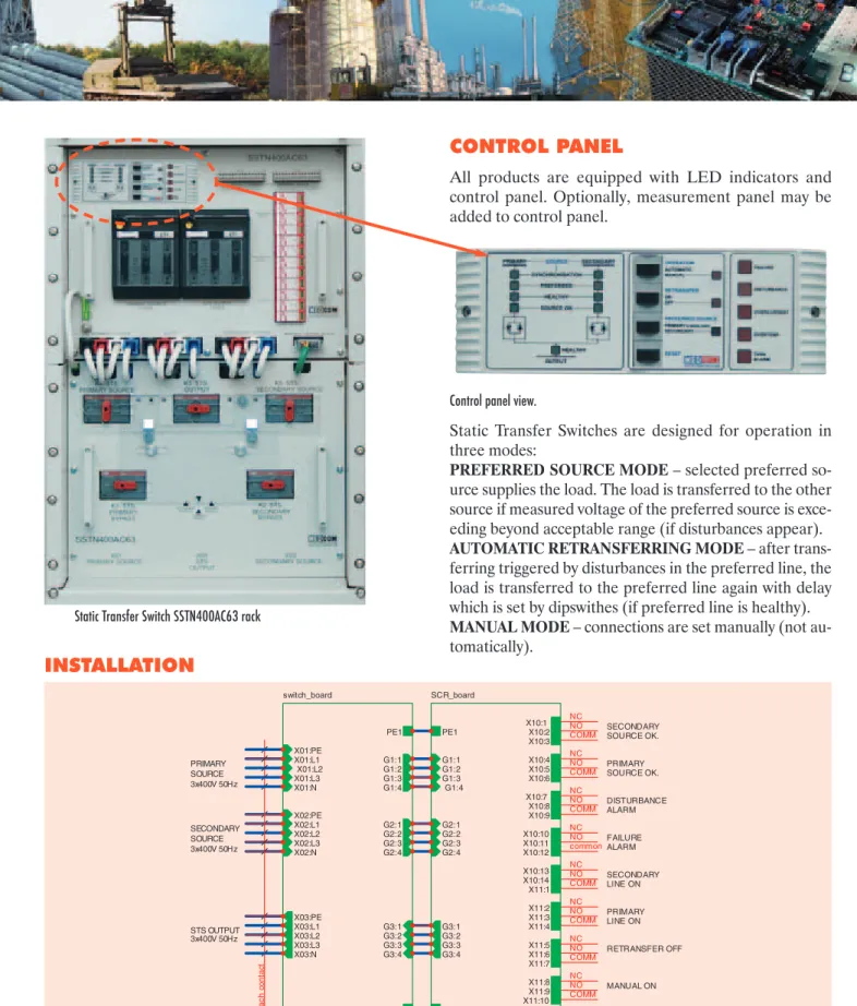
Static Transfer Switch SSTN400AC63 rack
CONTROL PANEL
All products are equipped with LED indicators and control panel. Optionally, measurement panel may be added to control panel.
Static Transfer Switches are designed for operation in three modes:
PREFERRED SOURCE MODE– selected preferred so-urce supplies the load. The load is transferred to the other source if measured voltage of the preferred source is exce-eding beyond acceptable range (if disturbances appear).
AUTOMATIC RETRANSFERRING MODE– after trans-ferring triggered by disturbances in the preferred line, the load is transferred to the preferred line again with delay which is set by dipswithes (if preferred line is healthy).
MANUAL MODE– connections are set manually (not au-tomatically).
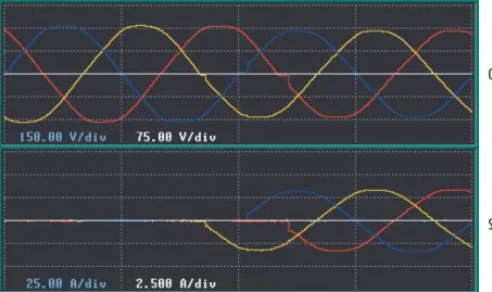
OSCILLOGRAMS
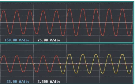
Fig. 9. SS transfer to redundant power source initiated by change of preferred input source.
Fig. 10. SS transfer to redundant power source caused by power interruption on preferred input source.
Fig. 11. SS transfer to redundant power source – unsynchronised lines.
PRIMARY SOURCE CURRENT SECONDARY SOURCE CURRENT
OUTPUT VOLTAGE
PRIMARY SOURCE CURRENT SECONDARY SOURCE CURRENT
OUTPUT VOLTAGE
PRIMARY SOURCE CURRENT SECONDARY SOURCE CURRENT
OUTPUT VOLTAGE
PRIMARY SOURCE CURRENT SECONDARY SOURCE CURRENT
Fig. 12. SST transfer to redundant power source initiated by change of preferred input source.
Fig. 13. SSTN transfer to redundant power source caused by power sag on preferred input source.
Fig. 14. SSTN transfer to redundant power source caused by power swell on preferred input source. PRIMARY SOURCE CURRENTS
OUTPUT VOLTAGES
PRIMARY SOURCE CURRENTS
OUTPUT VOLTAGES
SECONDARY SOURCE CURRENTS OUTPUT VOLTAGES
Fig. 15. SSTN transfer to redundant power source initiated by power interruption on preferred input source.
Fig. 16. SSTN transfer to redundant unsynchronised power source initiated by change of preferred input source – asymmetrical load.
Fig. 17. SSTN transfer to redundant synchronised power source – computer load. PRIMARY SOURCE CURRENTS
OUTPUT VOLTAGES
SECONDARY SOURCE CURRENTS OUTPUT VOLTAGES
SECONDARY SOURCE CURRENTS OUTPUT VOLTAGES
CONFIGURATIONS
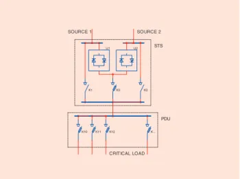
STS SETS FOR POWER DISTRIBUTION UNIT (PDU)
STS sets for power distribution unit (PDU) are produced by leading international companies. During production, simple PDU monitoring system based on STS control unit may be applied. Transfer to redundant source is caused by faulty operation of preferred source, for example when voltage range exceeds beyond acceptable range. It is possible to transfer “connection” on demand UPS system, for example when the state of batteries is getting too low. An instantaneous transfer is performed even before the preferred UPS voltage drops under acceptable value. SOURCE 2 SOURCE 1 K3 U2 K10 K11 K1 K2 STS CRITICAL LOAD K... K12 PDU U1
Fig. 18. STS set for power distribution unit.
TWO-STS SET FOR TWO-SECTION POWER DISTRIBUTION UNIT WITH A TIEBREAKER
Two-STS set for two-section power distribution unit with a tiebreaker allows independent operation of two STS-PDU section sets. It is possible to transfer both sections to one STS unit without interruption. The tiebreaker is switched on after prior maintenance-related transfer of both STS units to one of the power sources. When one of the STS units is switched off, the remaining STS provides independent redundancy power for the two PDU sections.
SOURCE 2 K... U2 K1 U1 K10 K... K3 K1 PDU2 K12 K11 K10 STS2 K100 PDU1 K2 K2 STS1 SOURCE 2 SOURCE 1 K11 K12 CRITICAL LOAD U2 U1 CRITICAL LOAD SOURCE 1 K3 tiebreaker
Fig. 19. Two-STS set for two-section power distribution unit with tiebreaker.
STS U2 K3 AC BYPASS INV U1 F1 CRITICAL LOAD K1 K2 DC SOURCE
Fig. 20. STS set for voltage inverters.
STS SET FOR VOLTAGE INVERTERS
STS set for voltage inverters. Independent voltage invert-ers with limited output current are susceptible to short-circuits and overloads caused by sags and outages in output current. An additional bypass through the STS unit to inverter output eliminates voltage outage. Trans-fer to redundant source is triggered by faulty operation of inverter, for example when voltage value or current value are not in acceptable range.
Y kVA UPS2 K1 K100 F1 PDU2 K11 X+Y kVA K3 P1 tiebreaker U2 X+Y kVA UPS1 SOURCE 1 U1 K10 synchronization STS2 K2 K11 B1 P1 U1 K3 X+Y kVA K... K12 PDU1 K10 B1 F1 CRITICAL LOAD X kVA SOURCE 2 K2 K1 U2 K12 STS1 X+Y kVA K... CRITICAL LOAD U1 K3 K2 K1 STS1 LOAD 1 K1 SOURCE 1 K2 LOAD .... STS2 U1 U2 SOURCE 2 U1 K1 STS... U2 LOAD 2 K2 U2 ... K3 K3
UPS SUPPLY SYSTEM WITH REDUNDANCY
UPS supply system with redundancy and with disconnection ability for one line are power sup-ply systems frequently used in computer centres. It enables proper mating of different UPS de-vices and provides continuous non-stop opera-tion even during periods of scheduled mainte-nance. It eliminates single point failure. UPS synchronisation is required.
Fig. 21. Local STS installation with a dual AC power system.
Fig. 22. Redundancy provided UPS powered installation with available failure disconnection.
LOCAL STS INSTALLATION WITH DUAL AC POWER SYSTEM
Local STS installation with dual AC power system. Con-ventional power systems are susceptible to voltage out-ages which are transferred to all loads placed below the short-circuiting or below high overloaded site. This phe-nomenon is seen especially in systems with low current limitation, for example in UPS systems. The dual AC power system eliminates voltage outage effects. Transfer of local STS units to redundant source is caused by faulty
operation of preferred source, for example when voltage range exceeds beyond acceptable range. Transfer is not performed if overcurrent in load occurs. Faulty load is dis-connected from the system by its STS unit (it keeps run-ning on the disrupted line while the remairun-ning STS units perform transfers to efficient power source). The instal-lation is highly recommended for complex power supply networks.
Power supply
Nominal input voltage 120 V 230 V For TN-C, and TN-S networks 3×208 V 3×400 V
3×480 V
Acceptable voltage range -25 % ÷+20 % Operation
Frequency 60 Hz 50 Hz
Frequency tolerance -9 % ÷+6 %
Transient voltage surge suppression level <1.5 kV For Iimp 15 kA 8/20us <1.0 kV For Iimp 5 kA 8/20us Dielectric strength test AC 2 kV 60 s
Efficiency >98 % >99 % for cos(φ) > 0,8
Output
Nominal output current 25 A, 40 A Available configurations: 63 A, 100 A ●1-phase 1- pole
150 A, 250 A ●1-phase 2-poles (neutral line switch) 400 A, 63 0A ●3-phases 3-poles
●3-phases 4-poles (neutral line switch)
Crest factor 3.5
Power factor cos (φ) 0.5 ÷1 Inductive, capacitive Transient voltage surge suppression level <1.5 kV For Iimp 15 kA 8/20us
<1.0 kV For Iimp 5 kA 8/20us
Overload capacity 125 % t = 1 h
400 % t = 5 s
800 % t = 0.4 s 1000 % t = 0.2 s 1500 % t = 20 ms Short-circuit strength of thyristor switches 3 kA / 20 ms In=25, 40, 63 A
8 kA / 20 ms In=100, 150 A 15 kA / 20 ms In=250, 400, 28 kA / 20 ms In=630 A Fuse interrupting capacity 50 kA
Switching
Selection of preferred input source L1 / L2 With or without retransfer after restoring preferred input source power
Remote selection of preferred input source L1 / L2 Two-state input for L1 / L2 line
Setting range for upper input voltage limit +6 % ÷+20 % by 3 % Switching to alternative source on exceeding the limit
Setting range for lower input voltage limit -8 % ÷-24 % by 4 %
Phase error limit for synchronised lines ±8° ÷±24° by 4° Setting by DIPSWITCH Switching interlock for output over current 3 In Setting by DIPSWITCH
6 In 9 In no interlock Manual transfer time for synchronised lines < 0.2 ms of a phase error within the limits
Automatic transfer time for synchronised < 6 ms lines of a phase error within the limits
Manual or automatic transfer time 12 ms Setting by DIPSWITCH for not synchronised lines 17 ms
25 ms 50 ms
Retransfer time 1 s Setting by DIPSWITCH
8 s (both lines healthy) 25 s
SPECIFICATIONS*
120 = 120V / 60Hz 208 = 3×208V / 60Hz 230 = 230V / 50Hz 400 = 3×400V / 50Hz 480 = 3×480V / 60Hz INPUT VOLTAGE
RULES FOR MARKING STATIC TRANSFER SWITCHES
SSTN 400 AC 630
SS 1-phase 1-pole static transfer switchSSN 1-phase 2-poles static transfer switch SST 3-phases 3-poles static transfer switch SSTN 3-phases 4-poles static transfer switch DEVICE NAME
25 = 25A 40 = 40A
63 = 63A 100 = 100A
150 = 150A 250 = 250A
400 = 400A 630 = 630A
OUTPUT CURRENT (NOMINAL PHASE LINE CURRENT)
Measurement of
Inputs sources voltage ±1 % ±1 V Optional equipment
Output currents ±2 % ±1 A
Active power P ±3 % ±0,1 kW
Apparent power S ±3 % ±0,1 kVA
Alarms
Failure Relay Overload
Overtemperature Fuse failure Internal STS failure
Disturbance Relay Primary source not healthy
Secondary source not healthy Lack of synchronisation
Transient voltage surge suppression alarm Manual control ON
Automatic retransfer switched OFF
Manual ON Relay Service operation
Retransfer OFF Relay Retransfer to preferred source is not perform Primary source OK. Relay Indicating if primary source is healthy Secondary source OK. Relay Indicating if secondary source is healthy Primary line ON. Relay Indicating if primary source is active Secondary line ON. Relay Indicating if secondary source is active
Alarm connectors parameters
Max operating voltage 300 V= or 250 V~ Max load capacity 4 A for 220 V~
0.3 A for 220 V=
Communications interface
Optional RS232 / RS485
Ambient conditions (storage and operation)
Operating temperature 0÷40 °C
Storage temperature 0÷40 °C
Relative humidity (noncondensing) max 98 % Installation Site Altitude below 1000 m
Air cooling Natural For In=25, 40, 63 A
Forced with built-in fan redundancy For In=100, 150, 250, 400, 630 A
EMC Class B EN55022, EN60555-2, EN60555-3
Enclosure
Degree of protection IP20
STATIC TRANSFER SWITCHES SERIES
Type UN [V]* Frequency [Hz]* IN [A] Losses [W] Enclosure
Dimensions
W × S × G [mm] Weight [kg] 1-phase 1-pole freestanding units
SS120AC25 120 60 25 70 Rack 126 340 × 507 × 440 26 SS120AC40 120 60 40 80 Rack 126 340 × 507 × 440 28 SS120AC63 120 60 63 120 Rack 126 340 × 507 × 440 30 SS120AC100 120 60 100 170 Sarel S2 1100 × 800 × 400 96 SS120AC150 120 60 150 250 Sarel S2 1100 × 800 × 400 105 SS120AC250 120 60 250 370 Rittal TS1 1900 × 800 × 500 135 SS120AC400 120 60 400 550 Rittal TS1 1900 × 800 × 500 162
1-phase 1-polerackmount 19” units
SS120AC25-RM 120 60 25 70 3U 133,5 × 483 × 415 9,5
SS120AC40-RM 120 60 40 80 3U 133,5 × 483 × 415 10,5
SS120AC63-RM 120 60 63 120 3U 133,5 × 483 × 415 12,5
MB120AC25-RM 120 60 25 - 3U 133,5 × 483 × 197 4,5
MB120AC63-RM 120 60 63 - 3U 133,5 × 483 × 197 5,5
1-phase 2-pole freestanding units
SSN120AC25 120 60 2 x 25 140 Rack 126 340 × 507 × 440 29 SSN120AC40 120 60 2 x 40 160 Rack 126 340 × 507 × 440 31 SSN120AC63 120 60 2 x 63 240 Rack 126 340 × 507 × 440 33 SSN120AC100 120 60 2 x 100 340 Sarel S2 1100 × 800 × 400 104 SSN120AC150 120 60 2 x 150 500 Sarel S2 1100 × 800 × 400 114 SSN120AC250 120 60 2 x 250 740 Rittal TS1 1900 × 800 × 500 165 SSN120AC400 120 60 2 x 400 1100 Rittal TS1 1900 × 800 × 500 190
1-phase 2-polerackmount 19” units
SSN120AC25-RM 120 60 2 x 25 70 3U 133,5 × 483 × 415 11,5 SSN120AC40-RM 120 60 2 x 40 80 3U 133,5 × 483 × 415 12,5 SSN120AC63-RM 120 60 2 x 63 120 3U 133,5 × 483 × 415 14,5 MBN120AC25-RM 120 60 2 x 25 - 3U 133,5 × 483 × 197 5,5 MBN120AC63-RM 120 60 2 x 63 - 3U 133,5 × 483 × 197 6,5 120V/60Hz 230V/50Hz
Type UN [V]* Frequency [Hz]* IN [A] Losses [W] Enclosure Dimensions
W × S × G [mm] Weight [kg] 1-phase 1-pole freestanding units
SS230AC25 230 50 25 70 Rack 126 340 × 507 × 440 26 SS230AC40 230 50 40 80 Rack 126 340 × 507 × 440 28 SS230AC63 230 50 63 120 Rack 126 340 × 507 × 440 30 SS230AC100 230 50 100 170 Sarel S2 1100 × 800 × 400 96 SS230AC150 230 50 150 250 Sarel S2 1100 × 800 × 400 105 SS230AC250 230 50 250 370 Rittal TS1 1900 × 800 × 500 135 SS230AC400 230 50 400 550 Rittal TS1 1900 × 800 × 500 162
1-phase 1-pole rackmount 19” units
SS230AC25-RM 230 50 25 70 3U 133,5 × 483 × 415 9,5
SS230AC40-RM 230 50 40 80 3U 133,5 × 483 × 415 10,5
SS230AC63-RM 230 50 63 120 3U 133,5 × 483 × 415 12,5
MB230AC25-RM 230 50 25 - 3U 133,5 × 483 × 197 4,5
MB230AC63-RM 230 50 63 - 3U 133,5 × 483 × 197 5,5
1-phase 2-pole freestanding units
SSN230AC25 230 50 2 x 25 140 Rack 126 340 × 507 × 440 29
SSN230AC40 230 50 2 x 40 160 Rack 126 340 × 507 × 440 31
SSN230AC63 230 50 2 x 63 240 Rack 126 340 × 507 × 440 33
SSN230AC100 230 50 2 x 100 340 Sarel S2 1100 × 800 × 400 104
Type UN [V]* Frequency [Hz]* IN [A] Losses [W] Enclosure Dimensions
W × S × G [mm] Weight [kg]
SSN230AC250 230 50 2 x 250 740 Rittal TS1 1900 × 800 × 500 165
SSN230AC400 230 50 2 x 400 1100 Rittal TS1 1900 × 800 × 500 190
1-phase 2-polerackmount 19”units
SSN230AC25-RM 230 50 2 x 25 70 3U 133,5 × 483 × 415 11,5 SSN230AC40-RM 230 50 2 x 40 80 3U 133,5 × 483 × 415 12,5 SSN230AC63-RM 230 50 2 x 63 120 3U 133,5 × 483 × 415 14,5 MBN230AC25-RM 230 50 2 x 25 - 3U 133,5 × 483 × 197 5,5 MBN230AC63-RM 230 50 2 x 63 - 3U 133,5 × 483 × 197 6,5 3 × 208V/60Hz
Type UN [V]* Frequency [Hz]* IN [A] Losses [W] Enclosure
Dimensions
W × S × G [mm] Weight [kg] 3-phase 3-pole freestanding units
SST208AC25 3 × 208 60 3 × 25 130 Sarel S2 1100 × 800 × 400 93 SST208AC40 3 × 208 60 3 × 40 180 Sarel S2 1100 × 800 × 400 100 SST208AC63 3 × 208 60 3 × 63 300 Sarel S2 1100 × 800 × 400 107 SST208AC100 3 × 208 60 3 × 100 450 Sarel S2 1100 × 800 × 400 120 SST208AC150 3 × 208 60 3 × 150 700 Rittal TS1 1900 × 800 × 500 195 SST208AC250 3 × 208 60 3 × 250 1100 Rittal TS1 1900 × 800 × 500 225 SST208AC400 3 × 208 60 3 × 400 1600 Rittal TS2 1900 × 1200 × 500 315 SST208AC630 3 × 208 60 3 × 630 2700 Rittal TS3 2240 × 1200 × 600 365
3-phase 3-pole rackmount 19” units
SST208AC25-RM 3 × 208 60 3 × 25 130 Rack 19” 710 × 483 × 465 60
SST208AC40-RM 3 × 208 60 3 × 40 180 Rack 19” 710 × 483 × 465 68
SST208AC63-RM 3 × 208 60 3 × 63 300 Rack 19” 710 × 483 × 465 72
SST208AC100-RM 3 × 208 60 3 × 100 450 Rack 19” 710 × 483 × 465 76
3-phase 4-pole freestanding units
SSTN208AC25 3 × 208 60 3 × 25 + 50 145 Sarel S2 1100 × 800 × 400 100 SSTN208AC40 3 × 208 60 3 × 40 + 80 195 Sarel S2 1100 × 800 × 400 107 SSTN208AC63 3 × 208 60 3 × 63 + 125 320 Sarel S2 1100 × 800 × 400 114 SSTN208AC100 3 × 208 60 3 × 100 + 200 480 Rittal TS1 1900 × 800 × 500 195 SSTN208AC150 3 × 208 60 3 × 150 + 300 850 Rittal TS2 1900 × 1200 × 500 225 SSTN208AC250 3 × 208 60 3 × 250 + 500 1425 Rittal TS2 1900 × 1200 × 500 315 SSTN208AC400 3 × 208 60 3 × 400 + 800 2300 Rittal TS3 2240 × 1200 × 600 365 SSTN208AC630 3 × 208 60 3 × 630 + 1000 3300 Rittal TS3 2240 × 1200 × 600 440
3-phase 4-pole rackmount 19” units
SSTN208AC25-RM 3 × 208 60 3 × 25 + 50 145 Rack 19” 710 × 483 × 465 64
SSTN208AC40-RM 3 × 208 60 3 × 40 + 80 195 Rack 19” 710 × 483 × 465 72
SSTN208AC63-RM 3 × 208 60 3 × 63 + 125 320 Rack 19” 710 × 483 × 465 76
Type UN [V]* Frequency [Hz]* IN [A] Losses [W] Enclosure
Dimensions
W × S × G [mm] Weight [kg] 3-phase 3-pole freestanding units
SST400AC25 3 × 400 50 3 × 25 130 Sarel S2 1100 × 800 × 400 93 SST400AC40 3 × 400 50 3 × 40 180 Sarel S2 1100 × 800 × 400 100 SST400AC63 3 × 400 50 3 × 63 300 Sarel S2 1100 × 800 × 400 107 SST400AC100 3 × 400 50 3 × 100 450 Sarel S2 1100 × 800 × 400 120 SST400AC150 3 × 400 50 3 × 150 700 Rittal TS1 1900 × 800 × 500 195 SST400AC250 3 × 400 50 3 × 250 1100 Rittal TS1 1900 × 800 × 500 225 SST400AC400 3 × 400 50 3 × 400 1600 Rittal TS2 1900 × 1200 × 500 315 SST400AC630 3 × 400 50 3 × 630 2700 Rittal TS3 2240 × 1200 × 600 365 3 × 400V/50Hz
Type UN [V]* Frequency [Hz]* IN [A] Losses [W] Enclosure
Dimensions
W × S × G [mm] Weight [kg] 3-phase 3-pole rackmount 19” units
SST400AC25-RM 3 × 400 50 3 × 25 130 Rack 19” 710 × 483 × 465 60
SST400AC40-RM 3 × 400 50 3 × 40 180 Rack 19” 710 × 483 × 465 68
SST400AC63-RM 3 × 400 50 3 × 63 300 Rack 19” 710 × 483 × 465 72
SST400AC100-RM 3 × 400 50 3 × 100 450 Rack 19” 710 × 483 × 465 76
3-phase 4-pole freestanding units
SSTN400AC25 3 × 400 50 3 × 25 + 50 145 Sarel S2 1100 × 800 × 400 100 SSTN400AC40 3 × 400 50 3 × 40 + 80 195 Sarel S2 1100 × 800 × 400 107 SSTN400AC63 3 × 400 50 3 × 63 + 125 320 Sarel S2 1100 × 800 × 400 114 SSTN400AC100 3 × 400 50 3 × 100 + 200 480 Rittal TS1 1900 × 800 × 500 195 SSTN400AC150 3 × 400 50 3 × 150 + 300 850 Rittal TS2 1900 × 1200 × 500 225 SSTN400AC250 3 × 400 50 3 × 250 + 500 1425 Rittal TS2 1900 × 1200 × 500 315 SSTN400AC400 3 × 400 50 3 × 400 + 800 2300 Rittal TS3 2240 × 1200 × 600 365 SSTN400AC630 3 × 400 50 3 × 630 + 1000 3300 Rittal TS3 2240 × 1200 × 600 440
3-phase 4-pole rackmount 19” units
SSTN400AC25-RM 3 × 400 50 3 × 25 + 50 145 Rack 19” 710 × 483 × 465 64
SSTN400AC40-RM 3 × 400 50 3 × 40 + 80 195 Rack 19” 710 × 483 × 465 72
SSTN400AC63-RM 3 × 400 50 3 × 63 + 125 320 Rack 19” 710 × 483 × 465 76
Type UN [V]* Frequency [Hz]* IN [A] Losses [W] Enclosure
Dimensions
W × S × G [mm] Weight [kg] 3-phase 3-pole freestanding units
SST480AC25 3 × 480 60 3 × 25 130 Sarel S2 1100 × 800 × 400 93 SST480AC40 3 × 480 60 3 × 40 180 Sarel S2 1100 × 800 × 400 100 SST480AC63 3 × 480 60 3 × 63 300 Sarel S2 1100 × 800 × 400 107 SST480AC100 3 × 480 60 3 × 100 450 Sarel S2 1100 × 800 × 400 120 SST480AC150 3 × 480 60 3 × 150 700 Rittal TS1 1900 × 800 × 500 195 SST480AC250 3 × 480 60 3 × 250 1100 Rittal TS1 1900 × 800 × 500 225 SST480AC400 3 × 480 60 3 × 400 1600 Rittal TS2 1900 × 1200 × 500 315 SST480AC630 3 × 480 60 3 × 630 2700 Rittal TS3 2240 × 1200 × 600 365
3-phase 3-pole rackmount 19” units
SST480AC25-RM 3 × 480 60 3 × 25 130 Rack 19” 710 × 483 × 465 60
SST480AC40-RM 3 × 480 60 3 × 40 180 Rack 19” 710 × 483 × 465 68
SST480AC63-RM 3 × 480 60 3 × 63 300 Rack 19” 710 × 483 × 465 72
SST480AC100-RM 3 × 480 60 3 × 100 450 Rack 19” 710 × 483 × 465 76
3-phase 4-pole freestanding units
SSTN480AC25 3 × 480 60 3 × 25 + 50 145 Sarel S2 1100 × 800 × 400 100 SSTN480AC40 3 × 480 60 3 × 40 + 80 195 Sarel S2 1100 × 800 × 400 107 SSTN480AC63 3 × 480 60 3 × 63 + 125 320 Sarel S2 1100 × 800 × 400 114 SSTN480AC100 3 × 480 60 3 × 100 + 200 480 Rittal TS1 1900 × 800 × 500 195 SSTN480AC150 3 × 480 60 3 × 150 + 300 850 Rittal TS2 1900 × 1200 × 500 225 SSTN480AC250 3 × 480 60 3 × 250 + 500 1425 Rittal TS2 1900 × 1200 × 500 315 SSTN480AC400 3 × 480 60 3 × 400 + 800 2300 Rittal TS3 2240 × 1200 × 600 365 SSTN480AC630 3 × 480 60 3 × 630 + 1000 3300 Rittal TS3 2240 × 1200 × 600 440
3-phase 4-pole rackmount 19” units
SSTN480AC25-RM 3 × 480 60 3 × 25 + 50 145 Rack 19” 710 × 483 × 465 64
SSTN480AC40-RM 3 × 480 60 3 × 40 + 80 195 Rack 19” 710 × 483 × 465 72
SSTN480AC63-RM 3 × 480 60 3 × 63 + 125 320 Rack 19” 710 × 483 × 465 76
3 × 480V/60Hz
MEDCOM Sp. z o.o.
ul. Barska 28/30 tel. +48(022) 314 42 00, 668 99 34, 668 69 84
02-315 Warszawa faks +48(022) 314 42 99, 668 99 29
e-mail: [email protected] website: www.medcom.com.pl
Since we are constantly incorporating the latest technological advances, our products are subject to modification. For this reason it may happen that certain elements of the above descriptions are no longer valid.
© 2005 MEDCOM. All rights reserved.
MEDCOM Sp. z o.o.
Founded in 1988, active in the design, manufacture, installation and servicing of modern electronic devices, aimed mainly at the power industry, military, railway and tramway transport, industry and health service customers. The use of latest technologies and system solutions, the services of highly experienced structural designers and the introduction of an ISO 9001:2001 Quality Assurance System, ensure that the devices produced are state-of-the-art and highly reliable. The technical design for all products is carried out in-house. In 2001 the company was awarded a prize The Polish President's Economy Award for THE BEST POLISH SMALL ENTERPRISE.
The most important products in the company's offer: • DC power supplies
• Uninterruptible power systems • High-voltage power supplies • Power supplies (MIL standards)
• Static converters for railway and tramway applications
• Power supplies for industrial applications • Power active filters
• Traction battery chargers • Static transfer switches • “Fail-safe” power supplies
• Motor driving systems: AC and DC motors • Measurement devices: battery earth fault meters,
battery operation monitors • Wind power converters