1
A survey on the contributions of Software-Defined
Networking to Traffic Engineering
Alaitz Mendiola, Jasone Astorga, Eduardo Jacob, Marivi Higuero
Abstract—Since the appearance of OpenFlow back in 2008, Software-Defined Networking (SDN) has gained momentum. Although there are some discrepancies between the standards developing organisations working with SDN about what SDN is and how it is defined, they all outline Traffic Engineering (TE) as a key application. One of the most common objectives of TE is the congestion minimisation, where techniques such as traffic splitting among multiple paths or advanced reservation systems are used. In such a scenario, this manuscript surveys the role of a comprehensive list of SDN protocols in TE solutions, in order to assess how these protocols can benefit TE. The SDN protocols have been categorised using the SDN architecture proposed by the Open Networking Foundation (ONF), which differentiates among Data-Controller Plane Interfaces, Application-Controller Plane Interfaces and Management Interfaces, in order to state how the interface type in which they operate influences TE. In addition, the impact of the SDN protocols on TE has been evaluated by comparing them with the Path Computation Element (PCE)-based architecture. The PCE-(PCE)-based architecture has been selected to measure the impact of SDN on TE because it is the most novel TE architecture until the date, and because it already defines a set of metrics to measure the performance of TE solutions. We conclude that using the three types of interfaces simultaneously will result in more powerful and enhanced TE solutions, since they benefit TE in complementary ways.
Index Terms—Software-Defined Networking, Traffic Engineer-ing, Network Resource Optimisation, Flow granularity.
I. INTRODUCTION
During the last decade, Software-Defined Networking (SDN) has emerged as a revolutionary networking paradigm, and has gained the attention of both the industry and the academia. Actually, SDN has been included in several reports as one of the most disruptive and interesting technologies in the networking area [1], [2]. Several factors have been decisive for the success of SDN. On the one hand, the vast range of SDN-enabled networking devices available in the market has been primordial. Both classical manufacturers such as Cisco [3], HP [4] or NEC [5] and novel manufacturers such as Corsa [6] are commercialising SDN products. On the other hand, the availability of open-source controllers with OpenFlow [7] support has fostered the implementation of SDN applications.
For the moment, there is no clear consensus about what SDN is and how it is defined. Most definitions agree on the availability of open programmable interfaces at networking de-vices and the separation of the control and forwarding planes.
The authors work at the Department of Communications Engineering of the University of the Basque Country UPV/EHU. Faculty of Engineering, Alda. Urquijo S/N, 48013 Bilbao, SPAIN Email: {alaitz.mendiola, jasone.astorga, eduardo.jacob, marivi.higuero}@ehu.eus
Nevertheless, most agents involved in the standardisation of SDN do agree on some possible applications. In addition to its utilisation in Data Center (DC) networks [8], campus networks [9], [10] and as an enabler for Network Functions Virtualisation (NFV) [11], SDN appears as a promising can-didate to enhance current Traffic Engineering (TE).
TE has always been one of the most challenging topics in communication networks [12]. As stated by the Internet Engineering Task Force (IETF), TE deals with the perfor-mance optimisation of operational networks, and plays a key role in the provisioning of services with Quality of Service (QoS) [13]. Being aware of the benefits that SDN can bring to TE, telecom companies such as AT&T have started to work on SDN-based solutions [14]. Similarly, Internet Service Providers (ISP) and Research and Education Networks (REN) have also started to analyse the applicability of SDN to their transport networks.
A service typically provided by the ISPs and RENs to satisfy the increasing demand of users with short-term, high-capacity and high-availability demands is Bandwidth on De-mand (BoD). Given the crucial role of TE for the provisioning of this type of service, many RENs have started to design and deploy SDN-based solutions. For instance, the Energy Sci-ences Network (ESnet) [15], the high-speed computer network serving the United States Department of Energy, is evolving the On-Demand Secure Circuits and Advance Reservation System (OSCARS) [16] from the Path Computation Element (PCE)-based architecture [17] towards SDN. Likewise, the pan-European research and education network G´eant is fol-lowing a similar approach to improve AutoBAHN, their BoD service provisioning tool [18].
SDN appears to RENs and ISPs as the enabler for next generation TE solutions thanks to its high network pro-grammability and the possibility it offers to apply new and powerful TE strategies. For example, the logically centralised control plane of OpenFlow makes possible to use PCE-like dedicated elements. This allows to perform complex path computations and to easily deploy novel advanced reservation mechanisms. Furthermore, it allows to extend current TE-dependant services to include fast failure recovery mechanisms (e.g., G´eant’s BoD service does not provide resilience) and enables the utilisation of more convenient flow-based TE strategies. In this regard, it is worth mentioning that most SDN technologies are flow-oriented, where a flow is defined as the sequence of packets identified by a set of common header fields. As a consequence, it is possible to perform per-flow operations to increase the network resource utilisation, such asflow relocationor flow disaggregation. In the former, Networking to Traffic Engineering, in IEEE Communications Surveys & Tutorials, vol. 19, no. 2, pp. 918-953, Secondquarter 2017" which has been published in final form at https://doi.org/10.1109/COMST.2016.2633579. Personal use of this material is permitted. Permission from IEEE must be obtained for all other uses, in any current or future media, including reprinting/republishing this material for advertising or promotional purposes, creating new collective works, for resale or redistribution to servers or lists, or reuse of any copyrighted component of this work in other works.
TABLE I GLOSSARY.
CE Control Element OCS OpenFlow Capable Switch
CLI Command Line Interface OLS OpenFlow Logical Switch CSPF Constraint-based Shortest Path First ONF Open Networking Foundation
DC Data Center ONOS Open Network Operating System
D-CPI Data-Controller Plane Interface OSCARS On-Demand Secure Circuits and Advance Reservation System
E2E End-to-end OSPF Open Shortest Path First
ERO Explicit Route Object OVS Open vSwitch
FE Forwarding Element OVSDB Open vSwitch DataBase FIB Forwarding Information Base P2P Peer-to-Peer ForCES Forwarding and Control Element Separation PCC Path Computation Client
GMPLS Generalized MPLS PCE Path Computation Element
H-PCE Hierarchical Path Computation Element PCEP Path Computation Element Communication Protocol I2RS Interface to the Routing System QoE Quality of Experience
IETF Internet Engineering Task Force QoS Quality of Service
IGP Interior Gateway Protocol REN Research and Education Network ISP Internet Service Provider RIB Routing Information Base LFB Logical Forwarding Block RSVP Resource Reservation Protocol LLDP Link Layer Discovery Protocol SDN Software-Defined Networking LSP Lable Switched Path SDO Standards Development Organization M-PCE Multiple Path Computation Element TCAM Ternary Content-Addressable Memory MPLS Multi-Protocol Label Switch TE Traffic Engineering
NE Network Element TED Traffic Engineering Database NSP Network Service Provider WAN Wide Area Network OCP OpenFlow Configuration Point WG Working Group
a flow can be moved to an alternative path, whereas in the latter, a flow is divided into multiple sub-flows in order to accept new service demands or balance the load. Furthermore, mechanisms such as flow relocation and disaggregation can be applied taking into consideration the characteristics of the traffic being forwarded, which as stated in [19], improves considerably the QoS metrics performance and therefore, TE strategies’ performance.
A. Contributions
This manuscript provides a literature review of the SDN-based TE solutions published until 2015. Moreover, it also analyses the impact of SDN on TE, making special emphasis on its contribution to the optimisation of the network re-source utilisation. Among the plethora of technologies usually included in the SDN environment, this survey analyses a comprehensive list of SDN protocols that impact TE. The protocols have been categorised taking into account the inter-face in which they operate, considering the SDN architecture proposed by the Open Networking Foundation (ONF). This architecture defines three interfaces: the Data-Controller Plane Interface (D-CPI), the Application-Controller Plane Interface (A-CPI) and the Management Interface (MI).
All in all, this survey provides a complete view of the impact of SDN on TE, in which SDN-based TE solutions applied to a variety of scopes are surveyed, such as Wide Area Networks (WAN), DC networks, or inter-DC networks. This paper concludes that the contributions to TE of the analysed SDN protocols is tightly coupled to the interface in which they operate. In this regard, the protocols operating at the D-CPI interface are the ones with a greater impact on TE, although the best course of action to provide enhanced TE in future networks is to use complete SDN frameworks with support for protocols operating at the three different interfaces.
But most importantly, this survey answers the question of how and why SDN can contribute to TE. In summary, SDN can benefit TE thanks to the higher granularity available at
the forwarding devices, making possible the utilisation of flow disaggregation mechanisms to improve the network re-source utilisation. On the other hand, the logically centralised controller plane allows the implementation of advanced path computation algorithms fed with up-to-date network state information. Furthermore, the high programmability and the logically centralised controller plane of SDN provides the means to react upon network failures.
B. Related work
As far as we know, this is the first survey about SDN entirely focused on its applicability to TE, which studies the impact of the different SDN interfaces on TE. Surveys like [20], [21] provide a general overview of SDN, while other papers are focused on more specific topics like security [22]– [24], programmability [25], network virtualisation [26], the controller plane [27], or its application to other network types such as optical networks [28] or mobile networks [29]. Most surveys are focused entirely on OpenFlow and its applications [30]–[32], some of which deal briefly with TE [33], [34]. However, none of the surveys analyse how different SDN protocols impact TE, and how the impact depends on the interface at which the protocol operates.
C. Structure of this paper
This document is structured as follows. First, Section II provides some background information about TE in packet networks, identifying the most common performance objec-tives and techniques used today. Furthermore, it briefly re-views the evolution of TE, and summarises the limitations found in today’s TE solutions that SDN-based approaches can solve. Then, Section III introduces SDN and the architectures proposed by the ONF and the Software-Defined Networking Research Group (SDNRG). This section also introduces the taxonomy used in this paper to categorise the SDN protocols, which is based on the interface types defined by the ONF’s
SDN architecture, namely D-CPI, A-CPI and MI. Section IV provides a review of the SDN protocols analysed in this paper, namely ForCES, OpenFlow, I2RS, BGPLS/PCEP, ALTO, OVSDB Management Protocol, NETCONF and OF-CONFIG. Later, Section V surveys current TE solutions where D-CPI protocols have been used, while Section VI and Section VII do the same with A-CPI and MI protocols respectively. Then, Section VIII provides a qualitative evaluation of the analysed protocols taking as reference the PCE-based archi-tecture. Section IX presents the lessons learnt in the form of a comprehensive list of future research areas. Finally, Section X summarises the conclusions. Table I presents the glossary used in this manuscript.
II. BACKGROUND: TEIN PACKET NETWORKS
This section introduces TE in packet networks and presents a list of common TE performance objectives and the tech-niques used to achieve them. Moreover, a brief overview of the evolution of TE in packet networks until the appearance of the PCE-based architecture is included. Finally, the limitations of current TE solutions are described, in order to identify how SDN can improve TE.
A. Definition of TE
In communication networks, TE consists in the application of strategies and scientific principles to optimise the perfor-mance of operational networks [13]. The general objective of TE is to route traffic in a data network so that traffic demands are met, by optimising a selected performance objective. This usually involves the computation of a path between a given source-destination pair, or the computation of multiple paths to share the load according to specific traffic-splitting ratios.
B. TE performance objectives and techniques
The performance optimisation of a network is an iterative process in which new technologies and optimisation mech-anisms are continuously required [12]. When a TE solution is designed, the performance objective must be selected care-fully, since different performance objectives can be mutually exclusive. This section presents a comprehensive list of per-formance objectives and the techniques that are used for their optimisation.
1) Congestion minimisation: In an operational IP context, congestion is one of the most important problems, since it affects delay, jitter and packet loss [12]. Therefore, it is one of the most critical performance objectives in current communication networks.
Congestion minimisation can be achieved using different techniques:
• Sharing the network resources by multiple traffic streams. • Re-allocating network resources by redistributing the
traffic over the infrastructure.
• Denying the access to congested resources. Once the congestion is detected, the TE system can only assign uncongested resources to new demands.
Sharing the network resources by multiple traffic streams is of special relevance for the congestion minimisation, since
it is a proactive technique aiming to avoid congestion. This is often achieved by minimising the links’ utilisation solving a traditional optimisation problem known as the minimum cost multi-commodity flow problem [35]. This optimisation problem has been widely studied in the literature [36]–[39] and it is an ongoing research work. The main purpose of this approach is to balance the traffic load along the network, which results in a better network utilisation. This is achieved by splitting the traffic into a set of streams that are routed through multiple paths connecting the ingress-egress router pair. As a consequence, the load is balanced among a higher number of network resources, resulting on a smaller amount of packets queued at the forwarding devices and less occupied bandwidth at the links.
A common approach to solve the multi-commodity flow problem is the computation of an optimal splitting ratio for the incoming traffic demand. Traffic splitting can be achieved in different ways. On the one hand, the most simple mechanism to split the traffic is on a per-packet basis, for example in a round-robin fashion. On the other hand, it is also possible to split the traffic on a per-flow basis, by applying a hash function over a set of the packets’ header fields. Current commercial routers can be configured to divide traffic based on the result of hashing different TCP/IP header fields.
As mentioned before, congestion can result in a higher end-to-end (E2E) delay and packet loss, therefore, the techniques used to minimise the congestion are also useful to minimise these two performance parameters. Notwithstanding, there are other factors besides congestion that can be the root cause of their degradation. As a consequence, the following sections present other techniques to deal with the minimisation of the E2E delay and the packet loss, where they are considered independent performance objectives. Furthermore, by optimis-ing these two performance objectives, the congestion is also minimised.
2) E2E delay minimisation: A typical network-related per-formance objective that impacts QoS and Quality of Experi-ence (QoE). The minimisation of the E2E delay is essential for critical real-time communications. It can be applied on a per-flow basis or as an overall objective that takes into account the E2E delay of all the packets transmitted in the network. One of the most common techniques to minimise the E2E delay is Constrained-Shortest Path First (CSPF), where the E2E delay is used as a constraint for the path selection [40].
3) Packet loss minimisation: Another typical network-related performance objective that can also be evaluated per-flow or network-wide. Besides congestion, packet loss can also be the result of failures in the network, such as forwarding de-vices and links, requiring additional techniques to increase the failure recovery capabilities of the network. This performance objective is usually tackled by over-provisioning the network to increase resilience [41] by means of redundant resources to be used in case of failure. In fact, if multiple paths are available to convey traffic between a given source-destination pair, traffic can be re-routed among the available paths when one of them suffers a disruption.
4) Energy consumption minimisation: This is a perfor-mance objective that does not necessarily match a network
performance parameter. It is widely used in the scope ofgreen computing[42], which aims to lower the environmental impact of Information and Communication Technologies (ICT). This performance objective is usually optimised either by adapting the rate of network operation to the offered workload or by reducing the amount of active resources [43]. In this last case, the energy consumption is reduced when traffic is gathered into a few paths and unused line cards can be powered down in the network equipment. This is a good example of how the different performance objectives can be mutually exclusive, since the minimisation of the energy consumption and the congestion minimisation cannot be achieved at the same time when this approach is followed.
5) Quality of experience maximisation: The Quality of Ex-perience (QoE), as defined by the European Telecommunica-tions Standards Institute (ETSI), is a parameter that measures the performance of using an ICT service or product taking into account objective technical parameters, like QoS, and subjective psychological parameters [44]. In other words, it is a parameter that gets affected by all the elements involved in the E2E transmission, including the end devices, environmental factors such as the light and the network performance. There-fore, the QoE maximisation also requires the optimization of the network performance, which is inside our scope of interest. Notwithstanding, maximising the QoE does not always imply the maximisation of the network throughput, and a correlation between the QoE criteria and the network-related performance parameters needs to be defined, as argued in [37].
6) Resource utilisation optimisation: The optimisation of the resource utilisation is another performance objective. For example, computation, buffer space and bandwidth are re-sources that need to be efficiently used, since they can impact congestion and other parameters. In addition, a good utilisation of the resources helps network operators to serve a higher number of service demands without increasing their costs. That is, a good utilisation of the network resources allows network operators to allocate a higher amount of traffic.
A common approach to optimise the network resource utilisation is to schedule well characterised data transfers. For instance, network operators can decide to transmit backup traffic between various data centers during the night hours, since more resources are available at that time. Advance reservation systems [45] are also used for the provisioning of the BoD service, since they are meant to optimise the bandwidth utilisation. Advance reservation systems allow to maintain a detailed inventory of the resource consumption over time and a better assignment of resources to satisfy new demands.
C. Evolution of TE
According to Awduche et al. [46], TE is considered a control issue where the element in charge of TE acts as a controller in an adaptive feedback control system. In this schema, available control actions must include the modifi-cation of traffic management parameters, the modifimodifi-cation of parameters associated with routing and the modification of the attributes and constraints associated with resources. Over the
years, TE in packet networks has been tackled using different approaches, as mentioned in the RFC 3272 [12]. However, first proposals were not appropriate for TE because they did not satisfy the aforementioned requirements posed in [46].
First routing protocols in the ARPANET were highly scalable and resilient distributed protocols but without the flexibility required by TE [47]. When the Internet became a reality, the adaptive routing protocols used in ARPANET were substituted by dynamic routing protocols. Though, the Interior Gateway Protocols (IGP) that run on the Internet were neither appropriate for TE, since the route selection was based on shortest path algorithms fed with additive link metrics and not on the resources available in the network.
As a first approach to take advantage of TE strategies in the Internet, overlay models were used, like IP over ATM [48]. By means of a secondary technology capable of establishing virtual circuits, point-to-point links between IP routers were served. This way, arbitrary virtual topologies were defined and superimposed onto the physical network topology that resulted on a much easier TE operation. Nevertheless, the use of overlay technologies increased the overall complexity of the network operation. In addition, these strategies were usually based on circuit pre-provisioning, given the lack of efficient mechanisms to create new circuits on demand.
Parallel in time, the Nimrod routing architecture was de-signed to provide service-specific routing taking into account multiple constraints [49]. Nimrod was based on the distribution of link-state maps that abstracted network connectivity and services information, and introduced the concept of explicit routing to allow the selection of paths at originating nodes. Even if this protocol was never deployed in the public Internet, it introduced some concepts adopted in more recent proposals, like explicit routing.
In the next iteration, Shortest Path First (SPF) algorithms that take into account the requested Type of Service (ToS) were proposed [50]. These approaches lead to an unfair usage of the network resources, where the shortest paths end up congested and other paths remain underutilised. Next, traffic splitting was introduced by means of the Equal Cost Multipath Protocol (ECMP), where traffic was split equally among all the available shortest paths [51]. Although the utilisation of traffic splitting mechanisms is not always optimal, which will be further explained in Section II-D, the use of ECMP is very extended, and many manufacturers support this protocol in their networking devices.
Later, the MPLS forwarding architecture emerged to provide flexibility and to increase the performance and scalability of the network layer routing [52]. In MPLS, packets are transmitted between the edge nodes of an MPLS domain using Label Switched Paths (LSP) and the forwarding decisions at each node are done based on previously assignedlabels. This results in a higher network performance, since the forwarding decision is performed using a single header field. MPLS is useful for TE because it provides most of the functionalities available from the overlay model in an integrated manner and at a lower level [13]. It supports the creation of explicit LSPs that are not constrained by the destination-based forwarding paradigm, facilitating the multi-path routing. Furthermore,
MPLS is appropriate for TE because it supports explicit routing and allows traffic aggregation and disaggregation, while the classical destination-based IP forwarding only sup-ports aggregation based on IP subnetting. In addition, with MPLS it is relatively easy to integrate constraint-based routing frameworks.
Finally, the IETF proposed the PCE-based architecture for MPLS and Generalized MPLS (GMPLS) networks [17], which extends packet switching capabilities of MPLS to an open set of networking and switching methods. The PCE-based architecture proposed a dedicated element to be in charge of the path computation making possible the application of complex algorithms such as CSPF. In addition, it supports the instantiation of point-to-point and point-to-multipoint LSPs, which is known as explicit routing. This architecture can be used when the path computation is CPU-intensive or when there is no visibility of all the network elements involved. As a consequence, this architecture is being adopted for TE [53], and can be used in intra-domain, inter-domain and inter-layer contexts.
D. Limitations of latest TE solutions
Since this survey is focused on the contributions of SDN to TE, it is important to identify the limitations of current TE solutions to determine in which areas SDN can pose an improvement. MPLS is the technology most widely used by network operators for TE, therefore, this section focuses on identifying the limitations found in MPLS-TE, including the limitations present in the PCE-based architecture, considered the most novel approach for TE in this type of networks. This section first identifies the limitations, and afterwards presents how SDN can improve each of them.
1) Unrealistic traffic splitting ratios: Congestion minimi-sation is often achieved using multiple paths, but the current mechanisms to split the traffic present some limitations. On the one hand, per-packet traffic splitting results in an excessive packet reordering in the destination endpoint node, which is undesirable, specially for TCP applications. As explained in [54], packet-level multipath routing can entail TCP seg-ments arriving out of order to the destination entity, triggering the TCP congestion avoidance mechanism unnecessarily and resulting on the application throughput and the whole network performance being degraded. In addition, jitter can occur, requiring large buffers to temporary store the packets received out of order. On the other hand, per-flow traffic splitting allows individual TCP or UDP flows to be distinguished, avoiding the traffic reordering problem. Nevertheless, the traffic splitting granularity is determined by the forwarding element and the hash function that is used to split the traffic. This granularity does not necessarily need to be the same granularity demanded by the TE solution, resulting in the assignment of inappropriate traffic ratios to each path. As a result, the overall network per-formance and the capacity of the TE mechanism to deal with congestion may not be optimal. In addition, traffic splitting mechanisms, such as ECMP, may not take into account the potential congestion of the shortest paths used to balance the traffic, which results in a poor performance [55].
SDN can help overcome this limitation thanks to the higher granularity available at the forwarding devices.
2) Unoptimal path computation algorithms: Path computa-tion and the required resource handling in MPLS-TE present some limitations as well. In [56], the authors detected that some of the links in an over-provisioned network were expe-riencing some latency. They analysed their MPLS-TE solution and deducted that latency inflation was a consequence of both the CSPF algorithm that they used and the continuous path changes that occur as a consequence of the autobandwidth
algorithm, which is provided by many MPLS vendors to automatically adjust the reserved bandwidth of the LSPs depending on the traffic demand.
SDN can help overcome this limitation thanks to the pos-sibility that it provides to perform the path computation at a logically centralised controller.
3) TE databases do not reflect the network state in real-time: Although the PCE-based architecture can improve such limitations of classic MPLS-TE, it also presents some limita-tions on its own. In the PCE-based architecture, path compu-tation is done using the TE information stored in the Traffic Engineering Database (TED). This database holds an inventory of the resources available in the network, information that is used by the PCE to compute the paths. Notwithstanding, according to the RFC 4655 [17], the TED does not always reflect the network state in real-time. When the TED is not properly synchronised with the network state, which can occur at specific times, the rate of wrong computed paths may increase.
SDN can help overcome this limitation thanks to its logically centralised control plane, which is aware of the network state in real-time.
4) Long convergence times of distributed protocols: An-other important limitation that can be found in MPLS-TE and in the PCE-based architecture is their dependence on RSVP-TE. When a network device requests a path, the PCE replies with the computed path information. Then, the network device uses the distributed protocol RSVP-TE to inform the other nodes. As a consequence, the establishment of the path can take more time than the one that is required by a centralised control plane with out-of-band programming capabilities. This has direct impact on the network stability and will impact on already established data flows. This fact also affects scalability as defined by the RFC 4655, because RSVP-TE is an in-band signalling protocol. This is a limitation that most MPLS-TE based solutions present, as they all rely on RSVP-TE.
SDN can help overcome this limitation thanks to the high network programmability that it provides, specially when the control of the network resources is done out-of-band.
All in all, TE has significantly evolved in MPLS networks. From the early implementations with MPLS-TE to the more advanced PCE-based solutions, the use of network resources is increasingly better. However, these MPLS-based TE solutions still present some limitations, such as the problems with the network state representation or the time required by the Label Distribution Protocol (LDP) to setup the LSPs. As a consequence, new approaches are envisaged, being the ones based on SDN the natural path to follow.
III. SOFTWARE-DEFINEDNETWORKING
This section presents the fundamentals of SDN, including a brief introduction to the history of SDN, its definition and the proposed architectures. In addition, the taxonomy used to categorise the different SDN protocols is presented.
A. Fundamentals of SDN
SDN is the result of three key research areas very popular since their inception in the mid 90s [57]. First, proposals like Open Signaling [58] and Active Networking [59] push in favor of network programmabilityby means of open interfaces and code piggibacked inside the user messages respectively. Sec-ond, thecontrol and data plane separationbring to the fore the possibility to control the network from an external entity [60] and the transition towards a logically centralised control plane [61]. Finally, the appearance ofnetwork operating systemsand the clean slate approach proposed at the 4D [62] project lead to the release of the OpenFlow switch specification and the SDN revolution.
According to the ONF [63], the changing traffic patterns within an enterprise DC, the need to accommodate the traffic of new personal devices in a fine-grained manner, the rise of cloud services and the associated increasing demand for net-work capacity are key computing and communication trends that require a new network paradigm such as SDN.
1) Definition: The ONF defines SDN as an emerging net-work architecture where the netnet-work is directly programmable and where the control and forwarding planes are decoupled. One of the main characteristics of SDN is that the intelligence is logically centralised in SDN controllers. Such controllers maintain a global view of the network, which results in the network appearing to the applications and policy engines as a single, logical switch [64].
With SDN, network design and operation are simplified because the entire network can be controlled from a logi-cally centralised point using open interfaces. Network control becomes vendor-independent and the utilisation of simpler network devices is a real possibility, since the devices only need to understand the SDN technology that controls them. One of the main features of this new paradigm is that networks can be programmatically configured, making possible the management of the entire network through intelligent orches-tration and provisioning systems. Besides, SDN architectures support a set of Application Programming Interfaces (API) that enable the implementation of common network services, custom tailored to meet business objectives.
2) Architecture: Nowadays, not only the ONF but many SDOs are dealing with SDN. For instance, the IETF has cre-ated an Internet Research Task Force research group focused on this trend, named the Software-Defined Networking Re-search Group (SDNRG). Both the ONF and the SDNRG have proposed different SDN architectures, which are described in this section.
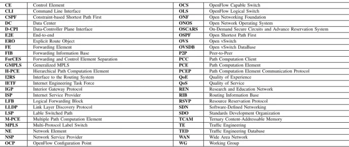
a) SDNRG Architecture: The architecture proposed by the SDNRG is depicted in Figure 1, and defines five different planes. Inside the network device, the forwarding plane is the one responsible for handling packets in the data path
Fig. 1. SDN architecture proposed by the SDNRG that consist of five different planes: forwarding plane, operational plane, control plane, management planeand application plane, two abstraction layers: Device and Resource Abstraction Layer (DAL)andNetwork Service Abstraction Layer (NSAL)and two interfaces to communicate the control plane with the forwarding plane and the management plane with the operation plane:CP Southbound interface andMP Southbound interfacerespectively.
and it is often referred to as the data plane. Secondly, the
operational plane is the plane responsible for managing the operational state of the network. On the one hand, thecontrol plane is the one in charge of taking the decisions about how packets are forwarded at network devices, and it is also in charge of pushing such decisions down to network devices so that they are executed. On the other hand, the management plane is the one in charge of monitoring, configuring and maintaining the network devices. Finally, theapplication plane
is where the applications that rely on the network to provide services for the end users and processes reside. In addition to these five planes, the SDNRG architecture also defines two abstraction layers: the Device and Resource Abstraction Layer and the Network Service Abstraction Layer. The first one abstracts the network devices’ forwarding and operational planes and connects to the control plane and management plane through the Control Plane Southbound Interface and theManagement Plane Southbound Interfacerespectively. The second abstraction layer exposes the control and management planes through a Northbound Interface to the application plane.
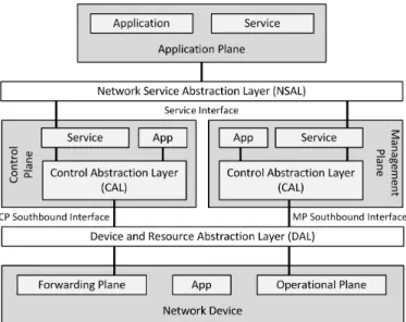
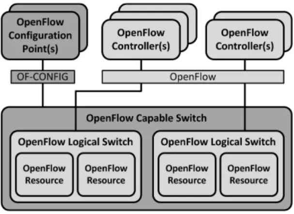
b) ONF Architecture: The ONF has also presented a reference architecture for SDN [65], which follows a three layer approach, as depicted in Figure 2. It has to be taken into account that the main goal of this architecture is to provide a high level overview of the reference points and open interfaces that should be present in every SDN deployment, in order to guarantee a minimum set of capabilities that would allow to control the connectivity provided by the network resources and the traffic flows through them.
The first layer is known as the data plane and it is the plane in which the network elements reside. The data plane uses the Data-Controller Plane Interface (D-CPI) to expose
Fig. 2. SDN architecture proposed by the ONF that consists of a data plane that communicates with a controller plane using a Data-Controller Plane Interface (D-CPI). The controller plane also communicates with the application planethrough anApplication-Controller Plane Interface (A-CPI), and the three planes are managed using theManagement Interfaces (MI).
the network elements’ capabilities to the second layer, that is, thecontroller plane. As its name suggests, the controller plane contains the SDN controller, which is the element in charge of controlling the network elements through the previously mentioned D-CPI. The controller plane also exposes services to the third layer, known as the application layer, through theApplication-Controller Plane Interface (A-CPI). This latter plane holds the applications that specify the behaviour of the network through the A-CPI. In addition to these two interfaces, this architecture also considers MI to configure and manage the three different planes.
B. Taxonomy
The SDN protocols analysed in this paper will be cate-gorised according to the interface defined by the ONF’s SDN architecture at which they operate. The three categories used in this paper are listed below:
• D-CPI protocols: used to communicate the data plane with the controller plane. The D-CPI is aware of an instance of the data plane’s informational model, that is, the set of resources on the data plane and the operations that can be performed on them. These protocols operate on an event timescale, that is, they are able to enable or disable circuits at the data plane within milliseconds. • A-CPI protocols: protocols that are used to
communi-cate the controller plane with the application plane. The protocols in this category can provide an abstraction of the network resources to the applications, or user-friendly and standardised mechanisms to program the network elements.
• MI Protocols:the ONF’s SDN architecture includes man-agement technologies to operate over the three planes. However, given that currently there are not standard-ised technologies to manage the controller plane or the application plane, this survey focuses on management technologies that operate over the data plane. Therefore, the MIs surveyed in this paper are used to manage the network elements, and are in charge of tasks such as policy provisioning, port, queues or LSPs configuration
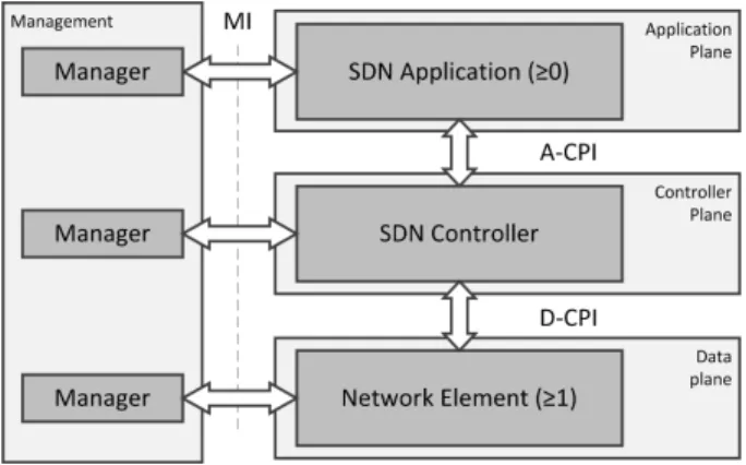
Fig. 3. Categorisation of SDN protocols depending on the interface at which they operate, namelyData-Controller Plane Interface (D-CPI), Application-Controller Plane Interface (A-CPI), and Management Interface (MI).
and in some cases, even of failure detection. They operate on much slower timescale when compared with the D-CPI protocols, within minutes or hours.
According to this taxonomy, the SDN protocols that are analysed in this paper are classified as depicted in Figure 3. On the one hand, OpenFlow, ForCES, I2RS and BGP-LS/PCEP are D-CPI technologies. On the other hand, NET-CONF, OVSDB Management Protocol and OF-CONFIG are MIs. Finally, ALTO is the only protocol identified as an A-CPI protocol.
IV. SDNPROTOCOLS
This section briefly reviews a comprehensive list of SDN protocols of interest for TE, which have been categorised taken into account the taxonomy described in Section III-B.
A. D-CPI protocols
As mentioned before, the D-CPI protocols are the ones used to communicate the data plane with the controller plane. ForCES, OpenFlow, I2RS and BGP-LS/PCEP lie into this category.
1) ForCES: Back in 2003, the ForCES WG of the IETF presented the Forwarding and Control Element Separation (ForCES) framework [66], which enables the separation of the control and forwarding planes of the network elements. Although the framework and the homonym protocol were designed to easily add new functionalities to the forwarding plane, neither the industry nor the academia adopted the pro-posal. In fact, due to the lack of open implementations of the ForCES protocol, the ForCES framework was ostracised [67]. Currently, with SDN being a hot topic, the ForCES WG has resumed the standardisation process. As stated in the RFC 3746 [68], ForCES does not only define a framework, but also standardises all the associated protocols that make possible the information exchange between the control and the forwarding planes. It can be considered as a framework aiming to improve network programmability through an open interface. However, unlike other SDN technologies, the ForCES framework does
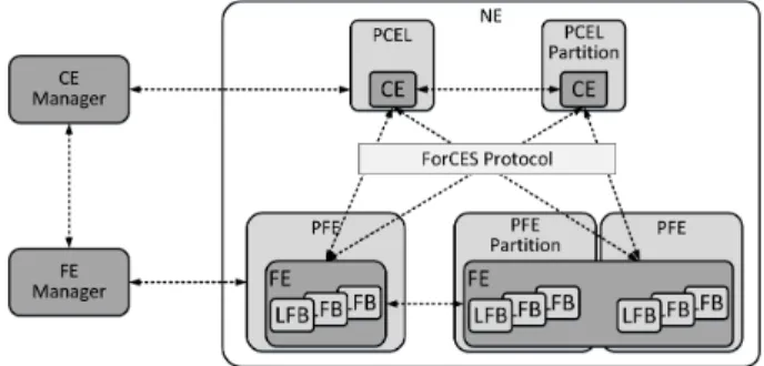
Fig. 4. ForCES framework elements where a Network Element (NE), composed of two Control Elements (CE), each of them residing on a Physical Control Element (PCEL), control two Forwarding Elements (FE) with multiple Logical Functional Blocks (LFB) that reside on one or multiple Physical Forwarding Elements (PFE) using the ForCES Protocol.
not impose a centralised control plane, in fact, it can be used with legacy distributed control protocols.
In the ForCES framework, which is depicted in Figure 4, a Network Element (NE) consists of Forwarding Elements (FE) and Control Elements (CE). In short, the FEs are logical entities that use the underlying hardware to provide per-packet processing. They must support a minimal set of capabilities to be able to establish network connectivity. FEs are formed by Logical Functional Blocks (LFB), which are programmed by the CE by means of the ForCES protocol to implement a wide variety of logical functions, e.g., L3 forwarding, Firewall or Network Address Translation. The FEs reside inside Physical Forwarding Elements (PFE), whereas CEs do the same in the Physical Control Elements (PCEL)1. Typically, the PFEs and the PCELs are placed in the same physical machine, although, they can also be located separately as specified by the RFC 6041 [69] by a single or multiple hops, as stated in RFC 6053 [70]. There are two operational phases identified in the ForCES framework. First, in the pre-association phase theCE managerand theFE managerdecide whether the CEs and the FEs are part of the same NE. However, this operational phase is out of the scope of the ForCES protocol. Second, in the post-association phase, the FEs and the CEs use the ForCES protocol to associate and exchange information to facilitate packet processing.
The ForCES protocol supports CEs redundancy. Multiple CEs can operate over the same FE, though, the coordination between the CEs is out of the scope of the ForCES protocol. As a consequence, it is possible for different CEs to implement different routing or signalling protocols, where the FE acts as the entity in charge of redirecting the control packets to each one of the CEs according to some filtering rules. Similarly, the framework also supports the coexistence of multiple FEs, which imposes additional challenges. First, the functions that each one of the FEs implement must be very well defined, as it can affect the overall performance of the system. Furthermore, depending on the functions that each FE is in charge of, it may be necessary to perform multiple forwarding decisions in more than one equipment.
ForCES is a master-slave protocol, with CEs acting as 1To avoid confusion with the Path Computation Element (PCE)
masters and FEs as slaves. The protocol provides the means to associate the different elements of the framework, so as to tear down such associations. It is also in charge of transmitting subscribed-to events from FEs to CEs and of responding to status requests issued from the CEs to the FEs. Additionally, it is used to configure the FEs and the associated LFBs’ operational parameters, so as to activate or deactivate the FEs. In the end, the protocol manages the LFBs at the FEs, which are compliant with the FE model defined in the RFC 5812 [71]. As mentioned before, the FEs are composed of LFBs that are interconnected in a direct graph, and receive, process, modify, and transmit packets along with metadata. The FE model establishes a formal way to define the FE’s LFBs using XML, while the configuration components, capabilities and associated events of the LFBs are defined when they are formally created. On the one hand, the FEs can be broadly defined by simply specifying their capabilities. For instance, FEs can be described in terms of IPv4 or IPv6 forwarding support or by the set of matching fields supported for the packet classification. On the other hand, the FE model can also be used to describe the FE state model, which presents a snapshot view of the FE to the CE. For each LFB, the number of inputs and outputs can be specified, as well as the packet types accepted in each of them and the routing criteria.
As stated in [72], the ForCES protocol is powerful enough to define other protocols. For instance, the authors of this paper state that both OpenFlow and NETCONF, which are later explained in this subsection, could be considered subsets of the ForCES protocol. Therefore, according to the ONF’s SDN architecture ForCES could be considered both a D-CPI and an MI. Nevertheless, since the primary goal of the ForCES protocol is the communication of the CEs with the FEs, that is, the controller and data planes of this architecture, it is considered a D-CPI protocol within the evaluation.
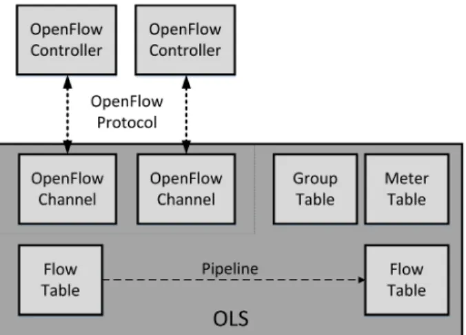
2) OpenFlow: Back in 2008, the Stanford University re-leased the first stable version of OpenFlow. Since then, the ONF has become the SDO in charge of the standardisation of the OpenFlow Switch Specification and its homonym protocol. The OpenFlow Switch Specification defines both the Open-Flow Logical Switch (OLS) and the OpenOpen-Flow protocol, used for the communication between the OLS and the OpenFlow controller.
As depicted in 5, the OLS consist of one or more control channels and a datapath. The datapath is where the packet lookups and forwarding are performed, by means of one or more flow tables, a group table and a meter table. The OLS connects to the external controller through the OpenFlow channel, often referred to as the control channel, using the OpenFlow protocol.
Each OLS must have at least a flow table composed of flow entries, which are formed by thematch fields, theprioritythat specifies the matching precedence of the entry, the counters
that hold statistical information, the set of instructions that are applied to the matching packets, the timeouts and the
cookie that unambiguously identifies the flow entry. Among the instructions that can be applied to packets, the ability to direct the packets to specificmetersis of special relevance for TE. Meters are switch elements able to measure and control
Fig. 5. Architecture on an OpenFlow Logical Switch (OLS), where at least oneOpenFlow Controllercommunicates with oneOpenFlow Channelusing theOpenFlow Protocolto program theGroup Table, theMeter Tableand the Flow Tableson the switch.
the rate of packets being forwarded; therefore, they play a key role in QoS enforcement. Instructions can also be used to apply a certain set of actions. Available actions include sending the packet to a queue or to an outport (output port), directing the packet to a group table or re-writing a specific field, to cite a few. Another interesting feature of OpenFlow is the fine-granularity that it supports for the matching of packets. OpenFlow takes into account at least the physical ingress port and additional Ethernet, IPv6, IPv4, TCP and UDP header fields. Moreover, additional header fields can be included thanks to the OpenFlow eXtensible Match (OXM), which is a very flexible model where new matching fields are defined as Type Length Values (TLV).
In a nutshell, the external controller populates the flow tables of the OLS with the flow entries that determine the behaviour of the traffic that matches them. Each OLS can contain more than one flow table with its corresponding flow entries. The OpenFlow pipeline process defines how packets interact with those flow tables. According to the latest Open-Flow Switch Specification [7], packets are always matched first against the first flow table and in the cases where there are multiple flow-tables, packets are forwarded to the subsequent ones. When a packet matches one or multiple flow entries, the instruction set associated to the entry with the highest priority is applied, which can include directing the packet to another flow table. Then, when the pipeline process finishes, either because there are not more redirections to subsequent flow tables or because it is the last flow table, all the associated actions are applied. It is worth mentioning that an OLS is able to handle flow miss-matches. Depending on the configuration, when a packet arrives that does not match any of the flow entries installed in a flow table, the OLS can specify how to process it. As a consequence, packets can be directed to another flow table or be sent to the controller. This feature makes possible to work reactively besides of proactively; that is, to act in response to packets that do not match any entry of a flow table.
There is a single group table per OLS, which makes possible
to represent additional forwarding methods. For instance, in an OLS it is possible to flood packets creating a group that associates output actions to all the ports but the ingress port. Each entry at the group table is defined by a unique identifier, a set of counters, the action buckets (ordered list of actions to execute and the associated parameters) that must be applied to the packets and the group type they belong to. For the moment, OpenFlow defines four different group types: all, select, indirect and fast fail-over. The first one is characterised by applying all the action buckets defined for the group. The
selectgroup type uses just one of the action buckets associated to the group for each packet, e.g., in a round-robin fashion. Third, theindirectgroup type supports a single action bucket. Finally, the fast fail-over group applies one action bucket at each time, following the order in which they are configured.
Regarding the OpenFlow controllers, it is worth mentioning that network operators can choose between centralised (e.g., NOX [73] POX [74], Trema [75], Ryu [76], FloodLight [77], Beacon [78], Maestro [79], McNettle [80], Jaxon [81], Snac [82]) or distributed (e.g., Onix [83], HyperFlow [84], Helios [85]) controllers. They can also select the programming language to use, being Java and Python the most popular ones. Furthermore, there are also available special purpose controllers, such as FlowVisor [86], Open Virtex [87] and AutoSlice [88], which make possible to virtualise OpenFlow-based networks by slicing the network resources and ex-posing the network control to other controllers transparently. For further information regarding network virtualisation with OpenFlow see [89]–[91]. In addition, several frameworks have appeared recently that support a set of SDN protocols, includ-ing OpenFlow. This is the case of the Open Network Operatinclud-ing System (ONOS) [92], OpenDaylight Platform (ODP) [93] or Cisco Open Networking Environment (ONE) [94]. Further information about OpenFlow controllers can be found in [95]. Undoubtedly, the OpenFlow protocol is a D-CPI, used to communicate the OLSs that reside in the data plane with the OpenFlow controller placed in the homonym plane of the ONF’s SDN architecture.
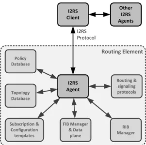
3) I2RS: The Interface to the Routing System, known as I2RS, is an IETF WG created in late 2012 [96]. This WG is actively focused on the definition of the I2RS protocol, the high-level architecture for its application and the key use cases for its operational use. In a nutshell, the I2RS protocol is a protocol [97] for transferring state into and out of the routing system that exploits the operating system of the router itself, that is, I2RS allows forwarding elements to keep their routing logic.
The majority of commercial routers maintain a Routing In-formation Base (RIB) and implement routing protocols such as OSPF, IS-IS and Border Gateway Protocol (BGP). The routing protocols insert routes into the RIB through the RIB Manager north-bound interface, while the Forwarding Information Base (FIB) manager consults the RIB and programs the FIB of the hardware. The I2RS harnesses the mechanisms that the routing systems and their operating system offer and provides an interface to control the RIB. In other words, I2RS interacts directly with the L3 forwarding engine and routing protocols. I2RS allows applications built on top of the network to
Fig. 6. Main components of the I2RS architecture (highlighted): the I2RS Agentthat communicates with theI2RS Clientusing theI2RS Protocol, and the interactions between the I2RS components and the components of legacy routing elements.
access the dynamic information that routers already have about the topology of the network, events, traffic and status. Thanks to the information they have access to, these applications are able to observe the routing related state of the routing elements, which allows them to enhance the routing control processes [98]. The I2RS architecture must be able to ensure that the correct state is operative [99], and to be able to do that, it defines the following elements [99], [100], where the most representative ones are depicted in Figure 6:
• I2RS Client: the entity that communicates with the I2RS Agents through the I2RS protocol and uses the I2RS Services to accomplish a task. It is able to interact with the I2RS Agents both, to collect information from the routing and forwarding system so as to modify the state of the routing system to achieve operational goals. Moreover, it can interact with other elements of the policy, provisioning and configuration system. The I2RS Client can be part of one or more applications and it may or may not be co-located with them.
• I2RS Agent: the entity that provides the supported I2RS services from the routing sub-systems of the local system. It is able to communicate with I2RS Clients through the I2RS protocol and it is considered a part of the routing element. The I2RS Agent is in charge of collecting and delivering the data obtained from the routing element, data that can be stored in a routing device or in an external element. Furthermore, it applies changes to the system and maintains a log with information about the changes and the active subscriptions.
• I2RS Service: a set of related state access functions and the policies that control their usage. Services can be associated to routing and label information bases, IGP, BGP and Multicast protocols, MPLS and Policy and QoS mechanisms. In general, to each logical protocol or set of functionalities susceptible of being described by a
separable data-model. Thus, each protocol or function-ality will be represented by a data-model that defines the semantics of the information that can be written or read. Furthermore, the data-model describes the notifications available to I2RS Clients and a capability model that determines the parts of a service that are supported. • I2RS Protocol: the protocol used between I2RS Clients
and I2RS Agents to communicate.
In order to provide programmability to the solution, the I2RS WG has specified an information model for the RIB, which can be used to define a data-model able to program a routing element [101]. For instance, a route data-model consists of a set of route attributes, the match condition (IPv4, IPv6, MPLS, MAC and Interface) and the next hop. The I2RS protocol makes it possible to write and read from the RIB information. Besides, being a standardised information model, it would be possible to use it to program multi-vendor routing elements.
As stated in [98], both the protocol and the modelling archi-tecture must be simple. I2RS data-models must be extensible and easy to integrate with other models. These data-models have to be able to model next hops and handle next-hop indirection and recursion, which allows flexibility and increases functionality. Besides, I2RS has to be able to handle different types of tunnelling and encapsulation methods. In addition, the solution is intended to support multiple simul-taneous asynchronous operations, multi-headed control, high throughput, responsiveness, secure control and extensibility and interoperability, among other features.
The I2RS protocol is meant to track and control the dynamic state of networking elements such as routers and switches. According to the I2RS WG, the I2RS protocol presents some major benefits. Firstly, it provides high flexibility to network operators since they can adapt their legacy networking hard-ware to SDN principles by installing an I2RS agent. I2RS relies on already existing technologies and therefore, already existing networking elements can be extended to implement the I2RS protocol by means of a firmware update. Secondly, it will be applied in highly reliable scenarios. Currently, the ODP supports I2RS data-models, which are defined using the YANG [102] modelling language.
In a nutshell, I2RS enables the distributed control protocols to coexist with the centralised management and control aspects provided by I2RS. It clearly operates at a different layer compared to OpenFlow and ForCES, but it is still an interface that allows to externally control the routing elements. As a consequence, I2RS is considered a D-CPI protocol within this survey.
4) BGP-LS/PCEP: Defined by the Inter-domain Router (IDR) IETF WG [103], BGP-LS is a protocol used to collect and share information about link state and TE [104]. By means of a set of extensions added to the BGP routing protocol [105], BGP-LS retrieves the topological information from the Link State Databases and distributes it to a consumer both directly or through a BGP Speaker or a Route Reflector. A BGP speaker exchanges network reachability information with other BGP speakers, including the intermediate ASs that the traffic must transit to reach destinations, whereas a Route
Reflector is mostly used as a concentrator for multiple BGP speakers inside an IGP area. Taking into consideration that BGP is an inter-AS technology, with BGP-LS it is possible to provide information about other IGP areas to the external components. Although it can work independently, BGP-LS is a mechanism that can also be used by multiple applications, such as PCE and ALTO. For example, PCE performs path computation using TE information, and TE information is never exchanged across different network domains. Since BGP-LS can be used to exchange TE information between different IGP areas and network domains, BGP-LS makes a PCE capable of computing E2E paths across different IGP areas. Thus, BGP-LS is a mechanism that can improve actual TE solutions such as the PCE-based architecture.
BGP-LS can be used to provide information about the maximum bandwidth, the maximum reservable bandwidth or the unreserved bandwidth on a given link. It can also be used to inform about the default TE metric. That is, to inform about the objective function of the TE strategy, such as the minimisation of the delay or of the link utilisation.
Many vendors have started to include BPG-LS support in their devices (i.e., Cisco or Juniper), so as many SDN platforms like the aforementioned ODP, ONOS and Cisco ONE [106]. BGP-LS by itself cannot be considered a full D-CPI technology, since it is only valid to exchange topological information among network elements and does not provide network programmability. However, most SDN controllers use BGP-LS together with the PCEP protocol, which is the reason why these two protocols working together are considered another D-CPI solution in this paper.
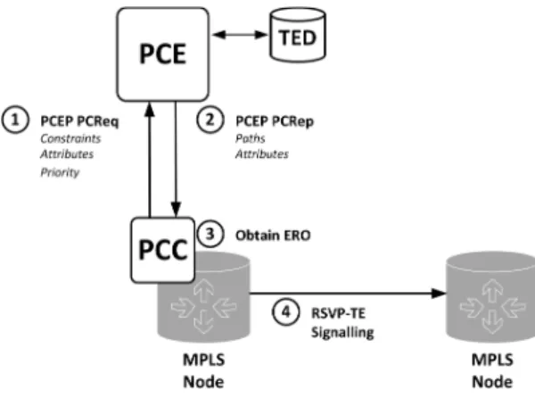
As mentioned before, the main characteristic of the PCE-based architecture is that the path computation is performed in a dedicated element. In this architecture, a Path Computation Client (PCC) requests a path, which is computed by the PCE using the TE information stored in a TED. In order to fulfil its intended objective, the PCE-based architecture relies on two key protocols: Path Computation Element Communication Protocol (PCEP) [107] and Resource Reservation Protocol (RSVP)-TE, defined in RFC 4657 [107] and RFC 3209 [108] respectively .
As stated in the RFC 4657 [107], the PCEP protocol is used for the communication between PCCs and PCEs, so as for the inter-PCE communication. Figure 10 depicts how a PCC communicates with a PCE to request a path computation. (1) the PCC sends PCEP PCReq messages to the PCE when it wants a path to be computed for one or more TE LSPs. Using the same message, it sends the set of constraints and attributes that the PCE requires to compute the path and a priority number to indicate the urgency of the request. When the PCE has finished computing the path, it replies (2) with a PCEP PCRep message, which can be a negative message indicating the reason why the computation has failed or a positive one. In the latter case, the response includes the set of computed paths and the sets of attributes associated with them, such as the path costs (e.g., cumulative link TE metrics and cumulative link IGP metrics) and the computed bandwidth. In order to avoid negative messages, the PCE can notify PCCs that it is unable to satisfy certain requests or that it has been
Fig. 7. Main components of the Path Computation Element (PCE)-based architecture and Path Computation Element Communication Protocol (PCEP) message exchange between the Path Computation Client (PCC) and the PCE.
experiencing unacceptable delays. This way, since the PCE-based architecture supports multiple PCEs in the same network domain, the PCC has the opportunity to send its PCReq to another PCE.
Using the PCEP protocol, (3) the PCEs send explicit paths to the PCCs specified by means of Explicit Route Objects (ERO). These EROs are used for the (4) establishment of the LSPs through RSVP-TE in MPLS and GMPLS networks. They consist of sets of IPv4/v6 prefixes and Autonomous Sys-tem (AS) numbers, among other possible parameters. Hence, the computation of the paths must support everything that can be expressed in an ERO, like the degree of paths disjointness or the maximum hop count among others. It is worth mentioning that PCEP includes support for load-balancing. The PCC can indicate the support for load-balancing and the number of paths that can be included in the balancing group. This is a very interesting feature for multi-path communications and the minimisation of the link load, because the more paths to split the traffic, the lower will be the load on each of them.
On the one hand, BGP-LS is able to retrieve topological and link state information but lacks the necessary mechanisms to program the network elements. On the other hand, PCEP is able to program the network elements but lacks the nec-essary mechanisms to retrieve information from the network resources. However, the two protocols complement each other, and working together compose another D-CPI technology to be taken into account. Working in conjunction with BGP-LS can lead the PCE-based architecture to a whole new level, since it can be useful to solve many of the limitations found regarding the retrieval of TE information to store it in the TED.
B. A-CPI protocols
Currently only one of the analysed protocols lies in this category, the ALTO protocol.
The Application Layer Traffic Optimization (ALTO) IETF working group [109] is in charge of the standardisation of the ALTO protocol since 2008, which is defined in RFC 7285 [110]. As a brief summary, the ALTO protocol provides information about the state of the network that allows to
improve both applications’ and network’s performance at the same time. The optimisation can be done taking into account different criteria: operator’s policies, geographical location, etc. The information provided by ALTO about the state of the network is neither granular nor in real-time, as it operates on a large time scale. According to the RFC 7285, the applications that use the information provided by the ALTO protocol can take better TE decisions. For example, an overlay application can use information provided by the ALTO protocol to avoid the links that impose higher delays than others. As a conse-quence, there have been some efforts from the IETF ALTO WG to integrate ALTO within SDN.
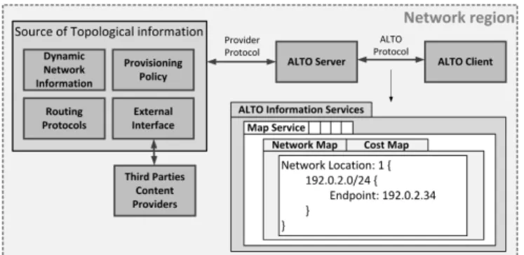
ALTO aims to improve traffic pattern distribution in cases where MPLS-TE or Diffserv do not provide any benefit. This is the case of distributed applications, such as peer-to-peer (P2P) communications, file sharing, cache/mirror selection, live media streaming, distributed hash tables or real-time com-munications. As depicted in Figure 8, in the ALTO architecture the following elements are differentiated [111], [112]:
• ALTO Service: when the same resource can be provided by different providers, it tells the requester which one must be selected in order to optimise both, the Quality of Experience (QoE) and the resource consumption in the underlying network infrastructure.
• ALTO Server: logical entity that provides interfaces for the queries to the ALTO service.
• ALTO Client:logical entity that sends ALTO queries. • ALTO Protocol: used for sending ALTO queries and
ALTO replies between an ALTO client and an ALTO server.
• Provisioning Protocol: used for populating the ALTO server with information.
• ALTO Information: a generic term referring to the net-work information sent by an ALTO Server.
• ALTO Information Base:internal representation of ALTO Information maintained by an ALTO Server.
• Endpoint: an application or host that is capable of com-municating (sending and/or receiving messages) on a network.
• Network Location: represents one or more endpoints. It is worth mentioning that the ALTO Server aggregates the information of multiple systems and provides it to the application on a more useful and unified way. Figure 8 shows how an ALTO Server is able to receive information from multiple sources, e.g., static network configuration databases, dynamic network information, routing protocols and provi-sioning policies. Furthermore, it is also capable of retrieving information from third party content providers using an ex-ternal interface. Each of these sources can provide a variety of network state related information with different purposes and different levels of detail. By combining them, the ALTO server is able to provide aggregated network state information, which represents network state more accurately.
The ALTO protocol follows a RESTful design and it is based on JSON over HTTP. Its main goal is to provide basic network location information and preferences of network paths in order to improve applications performance, while
Fig. 8. Main components of the ALTO architecture and details about how the network topology is presented to the ALTO Client by the ALTO Server.
resource consumption is also enhanced. In other words, the ALTO protocol is an interface that networks can use to publish heterogeneous information such as network locations, costs among them at configurable granularities, and endpoint properties to network applications. To be able to do that, ALTO exposes abstract maps of the network that provide a more simplified view of the network to the applications. On the one hand, thenetwork mapprovides a full set of Network Location groupings defined by the ALTO Server and the Endpoints contained within each grouping. On the other hand, thecost mapdefines thepath costspairwise for a given network map, that is, the E2E cost when a unit of traffic goes from the source to the destination among sets of source and destination Network Locations. Precisely, these cost maps are the elements that make possible for ALTO Servers to indicate preferences among Network Locations. Although the RFC 7285 specifies that the granularity is configurable, the Endpoints can only be defined with IPv4 or IPv6 addresses (prefixes are also supported) at the moment of writing this paper.
As proposed in [113], the ALTO server can be implemented as an SDN application on top of an SDN controller where the ALTO client resides. In such a scenario, the ALTO protocol which is in charge of communicating both entities will behave as an A-CPI as proposed by the ONF’s SDN architecture. At the moment of writing this manuscript there are not many solutions for ALTO, specially in the SDN environment, while the ALTO project in the ODP represents the most successful initiative until today.
C. MI protocols
The present section reviews a comprehensive list of SDN protocols that operate at the MI: OVSDB Management Proto-col, NETCONF and OF-CONFIG.
1) OVSDB management protocol: In brief, Open vSwitch DataBase (OVSDB) Management Protocol is a protocol that makes possible to manage the resources in an Open vSwitch (OVS) and it is defined in RFC 7047 [114]. OVS is an open-source multi-layer software switch released under Apache 2.0 license [115]. It was created in 2009 as a result of a collaborative project between Nicira Networks and members of the Computer Science Division of the University of Cali-fornia, Berkeley. Due to its good performance, the OVS was committed to the Linux Kernel in its 3.3 release [116]. It was
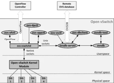
Fig. 9. Main components of the Open vSwitch (OVS) architecture placed in the physical, kernel or user space. OVS exposes two interfaces to external components: OpenFlow and OVSDB Management Protocol.
originally built for its application in virtual environments, more specifically, to be in charge of the inter-VM and intra-VM connectivity. Nevertheless, it has evolved and now it is used in a variety of environments [117]. For instance, it is possible to use it as the control stack of hardware switches [118].
Even that OVSDB Management Protocol can only be used with OVSs, it has been included in this survey as it is a very relevant SDN technology. According to [119], OVS exposes two well-defined interfaces; OpenFlow for the control of the forwarding behaviour and OVSDB for the configuration of the switch. The first interface has been analysed in Section IV-A2, whereas this subsection is focused on OVSDB.
As depicted in Figure 9, OVS runs both in the kernel and the user space. The ovsdb is the OVS database that stores the configuration information of the switch, which is precisely the database that is manipulated by the OVSDB Management Protocol. The information stored at the ovsdb is retrieved by the ovs-vswitchd daemon at startup time, and this information is later used for setting up the configuration of the switch and the corresponding datapaths. It is worth mentioning that when a change occurs in the ovsdb, the ovs-vswitchd automatically updates the switches’ configuration accordingly. Broadly speaking, the ovsdb is a database that holds the configuration used by the vswitch daemon [120]. The configuration information is held in well-defined tables that store specific information about bridges or ports, to cite a few.
The architectural components of the OVS are organised in two clusters: the management cluster and the control cluster. The former one encompasses the managers that use the OVSDB Management Protocol to manage the OVS instances, where there is at least one manager per OVS instance. On the other hand, the latter one encompasses the controllers that use the OpenFlow protocol to install the forwarding state into the OpenFlow switches, where there is at least one controller per OpenFlow bridge or logical datapath. Further information about these components can be found on the OVS website [121].
As defined in [114], the OVSDB Management Protocol is based on JSON Remote Procedure Call (RPC) version 1.0 [122] and its purpose is to operate on the OVS instance. Through the OVSDB Management Protocol it is possible to create, modify and delete OpenFlow datapaths. Furthermore, it provides the means to configure these OpenFlow datapaths. For instance, it supports the creation, modification and deletion of ports, tunnels and queues, so as the configuration of QoS policies and the attachment of those policies to the queues. It is also able to handle the configuration of the set of controllers to which an OpenFlow datapath should connect and collect statistical information. All in all, OVSDB is an MI protocol that allows to remotely configure OVSs
2) NETCONF: The main goal of the NETCONF proto-col is to provide a unified, cross-vendor and inter-operable management interface for automated control of network equipment. This feature makes NETCONF a very powerful tool for implementing the network management model re-quired by programmable networks [123]. NETCONF has been widely adopted by network equipment vendors. Among others, Cisco [124], Juniper [125] or NEC [126] support NETCONF in their commercial products. In a nutshell, the NETCONF protocol exposes an API that external applications can use to manage network devices, it follows a RPC paradigm and it is defined by means of a XML schema. The protocol is maintained by the IETF Network Configuration working group [127], which since the first release of the protocol back in 2006 has published more than 10 RFCs.
Through this protocol, applications and users are able to access the syntactic and semantic content of the device’s native user interfaces. Furthermore, it allows to discover the set of protocol extensions supported by network devices. It is often said that NETCONF is focused on the information required to get the device into its desired running state. When talking about NETCONF, the following terminology is used in RFC 6241 [128]:
• Client: the element that invokes the protocol operation on the server, usually an application or a script running in the Network Management System (NMS). It can also receive notifications from a server.
• Server:the element that executes the protocol operations invoked by a client, it is usually the network device itself. It can also send notifications to a client.
• Configuration data: the set of writeable data that is required to transform a system from its initial default state into its current state.
• State data: additional data on a system that is not configuration data such as read-only status information and collected statistics.
• Configuration datastore: the datastore holding the com-plete set of configuration data that is required to get the device from its initial default state into a desired operational state.
The configuration model followed by NETCONF is char-acterised by the definition of one or more configuration datastores that support a well-known set of operations. For instance, the running-configuration datastore holds the active configuration of the network device. Each device has one