The study of Cross-Coupling Effects (CCE)
in series connected Distributed MPPT
systems
A thesis submitted in partial fulfilment of the requirements for the degree of
Master of Technology
in
Electrical Engineering
(Specialization: Power Electronics & Drives)
by
SATYABRAT SABAT
Department of Electrical Engineering
National Institute of Technology, Rourkela
The study of Cross-Coupling Effects (CCE)
in series connected Distributed MPPT
systems
A thesis submitted in partial fulfilment of the requirements for the degree of
Master of Technology
in
Electrical Engineering
(Specialization: Power Electronics & Drives)
by
Satyabrat Sabat
under the guidance of
Prof. Somnath Maity
Department of Electrical Engineering
National Institute of Technology, Rourkela
Department of Electrical Engineering
National Institute of Technology, Rourkela
CERTIFICATE
This is to certify that the project entitled, “
The study of the Cross-Coupling Effects
(CCE) in series connected Distributed MPPT systems
” submitted by
Satyabrat
Sabat
in “
Power Electronics & Drives
” specialization is an authentic work carried
out by him under my supervision and guidance for the partial fulfilment of the
requirements for the award of
Master of Technology
in
Electrical Engineering
during the academic session
2014-2015
at
National Institute of Technology
,
Rourkela
. The candidate has fulfilled all the prescribed requirements. The Thesis
which is based on candidate’s own work, has not been submitted elsewhere for any
degree. In my opinion, the thesis is of standard requirement for the award of a Master
of Technology in Electrical Engineering.
X
Date: Dr. Somnath Maity
Place: Dept. of Electrical Engg.
ACKNOWLEDGEMENT
Firstly, I am grateful to the Department of Electrical Engineering, for giving me the opportunity to carry out this project, which is an integral fragment of the curriculum in M. Tech programme at the National Institute of Technology, Rourkela.
I would like to express my heartfelt gratitude and regards to my project guide, Prof. Somnath Maity, for being the corner stone of my project. It was his incessant motivation and guidance during periods of doubts and uncertainties that has helped me to carry on with this project. I would also like to thank Prof. A.K Panda, Head of the Department, Electrical Engineering, for his guidance and support.
I would also like to thank a lot of other friends for giving a patient ear to my problems. I am also obliged to the staff of Electrical Engineering for aiding me during the course of our project.
Finally, I would like to take the opportunity to thank my parents and my brother for their constant support and encouragement during my entire Post Graduate programme.
SATYABRAT SABAT 213EE4335
ABSTRACT
One of the abundant available renewable source of energy that has attracted interest of researchers today has been the solar energy. The demand for the harvesting of maximum energy has called for innovation of newer methods or technologies so that the PV panel can be operated at its peak power under partial shading and various dynamic atmospheric conditions.
In this thesis, we have discussed the modeling of a PV module. We have observed the characteristics of the PV module for different temperatures and solar insolation. The Perturb & Observe (P&O) maximum power point tracking algorithm has been employed to operate the panel voltage at its MPP. The direct duty ratio control has been employed. The demand for high voltage operations requires the PV modules to be series connected. So, when the modules are series connected, under partial shading and various dynamic atmospheric conditions the classical MPPT control strategy fails. The Distributed Maximum power point tracking (DMPPT) control technique has been a good replacement to the classical MPPT algorithm. So the DMPPT technique has also been discussed thoroughly. Under partial shading conditions there has been seen some peculiarities in the system when the modules are series connected. Such peculiarities are known as the Cross-Coupling Effects (CCE). The coupling effects have been studied and detected thus.
CONTENTS
List of Figures
List of Tables
Chapter 1 Introduction 1
1.1
Literature Review 2
1.2
Thesis Objective 3
1.3
Thesis Layout 3
Chapter 2 Analysis & Modeling of a PV based system 5
2.1 Introduction 5
2.2 Presentation & Modeling of a PV module 6
2.3 Determination of Parameters 9
2.3.1 Determination of
𝐼
𝑝ℎ9
2.3.2 Determination of
𝐼
𝑜10
2.3.3 Determination of
𝑅
𝑝&
𝑅
𝑠12
2.4 Conclusion 13
Chapter 3 Maximum Power Point Tracking Algorithms 14
3.1 Introduction 14
3.2 Fractional Open-Circuit Voltage 17
3.3 Fractional Short-Circuit Current 17
3.4 Incremental Conductance Algorithm 18
3.5 Perturb & Observe (P&O) Algorithm 19
3.6 Improvement of (P&O) Algorithm 22
Chapter 4 Distributed Maximum Power Point Tracking 24
4.1 Introduction 24
4.2 Limitation of Standard MPP Tracking 25
4.3 Distributed MPPT: A Novel Approach 26
4.3.1 Distributed MPPT using Micro-Inverters 26
4.3.2 Distributed MPPT using DC/DC Converters 30
4.4 PV array with DMPPT- DC Analysis 30
4.5 Conclusion 31
Chapter 5 Cross-Coupling Effects in Distributed DC/DC converters in PV
applications 33
5.1 Introduction 33
5.2 Witnessed cross-coupling effects 35
5.3 Conclusion
39
Chapter 6 Results & Discussions 40
I Conclusion 46
II
Future Work 47
LIST OF FIGURES
Figure No.
Figure Description
Page No.
Fig. 2.2(a)
Ideal single diode model of a PV module
6
Fig. 2.2(b)
Practical model with
𝑅
𝑠of a PV module
8
Fig. 2.2(c)
Practical model with
𝑅
𝑠and
𝑅
𝑝of the PV
module
8
Fig. 3.1
Block Diagram of PV system dedicated to a
DC/DC converter
16
Fig. 3.2
MPPT implementation
16
Fig. 3.3
Basic P&O configurations
20
Fig. 3.4
Basic flowchart for P&O MPPT algorithm
21
Fig. 4.1
PV system with FMPPT
25
Fig. 4.2
Micro-Inverter based DMPPT system
28
Fig. 4.3
DMPPT using dedicated DC/DC converters
30
Fig. 5.1
Series DMPPT structure
37
Fig. 5.2
Parallel DMPPT structure
37
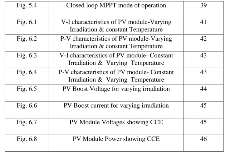
Fig. 5.4
Closed loop MPPT mode of operation
39
Fig. 6.1
V-I characteristics of PV module-Varying
Irradiation & constant Temperature
41
Fig. 6.2
P-V characteristics of PV module-Varying
Irradiation & constant Temperature
42
Fig. 6.3
V-I characteristics of PV module- Constant
Irradiation & Varying Temperature
43
Fig. 6.4
P-V characteristics of PV module- Constant
Irradiation & Varying Temperature
43
Fig. 6.5
PV Boost Voltage for varying irradiation
44
Fig. 6.6
PV Boost current for varying irradiation
45
Fig. 6.7
PV Module Voltages showing CCE
45
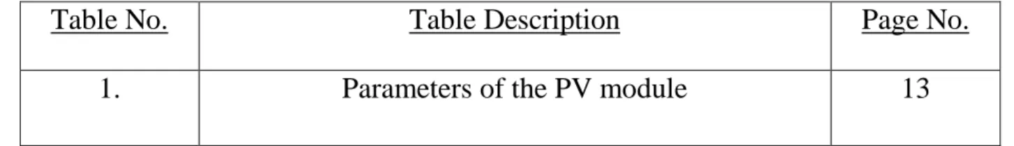
LIST OF TABLES
Table No.
Table Description
Page No.
Page | 1
CHAPTER 1
Introduction
In the course of recent years because of the development of power stress in the whole world, the accessible renewable wellspring of energy have put on more consideration towards power generation. Especially as there is broad stress with the world's energy requests, natural issues and lack of non-renewable wellspring of energies created by normal force era sources, for example, non-renewable sources like coal, diesel, characteristic gas and atomic energizes. Renewable energy sources, for example, wave vitality, sun powered vitality and wind vitality may be the exact answer for all these power issues [2]. Sun based vitality is a novel methodology for power generation and it is an extremely engaging renewable source amongst all the aforementioned renewable sources because of nearly little framework size, accessible at no expense and eco-accommodating era source or fuel, clamor free set up because of the nonattendance of moving parts, the upside of putting it near to the client, straightforwardness of establishment and frameworks require relatively minimal reliable upkeep.
All things considered, the viability of the sun oriented panels is too low. Their capacity to change over daylight to electrical force is relatively uneconomical, with transformation productivity generally fluctuating in the midst of 10 ~ 25 % as given in [1]. The window of proficiency can at present fall further amid flighty sun powered illumination, load conditions and panel temperature [1]. The complete framework expense can be lessened and operation is plausible at better effectiveness if the sunlight based board is ceaselessly worked to concentrate as much
Page | 2 power as doable by justifying that the panel is constantly worked under ideal force conveying conditions [7]. To finish this, maximum power point tracker (MPPT) frameworks are locked in. An ordinary MPPT framework contains a switched-mode power converter embedded in the midst of the PV module, and the duty cycle of the converter is managed by a control calculation to encourage following of the MPP.
Vibrant atmospheric conditions and halfway shading reduces the viability of the PV board [1]. The increment in examination in this field has additionally diminished the expense of sun oriented vitality. Therefore Solar Energy has earned a lot of significance even in the country zones and nowadays control creation from sunlight based energy has turn into a noteworthy part in the field of force generation. It is one type of vitality that is clean and is free from any wellbeing risks.
1.1 Literature Review
A number of literatures have been suggested on designing of a Photovoltaic array. Habbati Bellia, Ramdani Youcef, Moulay Fatima have modeled and simulated the PV array [2]. This paper offers a thorough modeling of the influence of irradiation and temperature on the parameters of the PV module and gives an idea about their characteristics. [3] shows the different cascaded dc-dc converter configuration by which the modules can be designed and is also shown that the converters i.e. buck & boost topologies, for a given cost, are the topologies with better performance.
J.Huusari and T.Suntio have demonstrated in [4] that the photo-voltaic clusters are defenseless to sporadic environment impacts or the flighty climate impacts, delivering generous decrease in grid output power. To get over this, Distributed maximum power point tracking framework has been embraced and they have demonstrated the presence of operational eccentricities the purported
Page | 3 cross-coupling impacts in arrangement associated disseminated DC/DC converters in photo-voltaic applications.
An exceptional outline on genuine outcomes of the talked about cross couplings is exhibited in [5]: A framework embodying three arrangement associated DC/DC converters has been explored. The MPPT block sustained the duty cycle straightforwardly to the converter when the framework was worked in open-loop MPPT mode.
1.1
Thesis Objective
To analyze the solar cell model and note its characteristics.
To study and to implement the Perturb & Observe algorithm.
To study and implement the Distributed MPPT technique (2 series connected PV modules)
in the MATLAB-Simulink environment.
To study, and to detect the presence of Cross-Coupling Effects in series connected DMPPT
systems.
1.2
Thesis Layout
The need and the importance of solar energy has been briefly introduced in the first chapter followed by a literature review in this context has also been presented. Subsequently the second chapter deals in the analysis and modeling of a single diode PV module. The equations used to model the PV module has been discussed thoroughly. The third chapter covers the various type of MPPT techniques used these days. Out of those MPPT techniques the Perturb & Observe MPPT algorithm used in the project work throughout has been elaborated. Then we have the fourth
Page | 4 chapter where a detailed study of the Distributed MPPT systems and its advantages over classical MPPT control has been done. The fifth chapter entirely covers the basis of the cross-coupling effects in series connected DMPPT systems and finally the last chapter contains the fallouts and deductions.
Page | 5
CHAPTER 2
Analysis & Modeling of a PV based system
2.1 Introduction
The PV module acts as an interface that converts light into electricity. The model of this
device, necessarily requires taking weather data (irradiance and temperature) as input variables. The output can be current, voltage, power or other. However, tracing the I(V) or P(V) characteristics needs these three variables. Any change in the entries immediately implies change in output variables. That is why, it is important to use an accurate model for the PV module. This chapter presents a detailed modeling of the influence of irradiance and temperature variations on the parameters of photo-voltaic modules. The chosen model is a single diode model with both series and parallel resistors for greater accuracy.
While modeling any system or model, the number of unknown parameters increases when the equivalent circuit of the chosen model or system gets more convenient and far from being the ideal form. As of the manufacturer’s data sheet, they do not give enough information about the parameters that depend on the weather conditions (irradiance and temperature). So, some assumptions with respect to the physical nature of the cell behavior are necessary to establish a mathematical model of a PV cell and the PV module. So, the goal is to obtain at any time, the maximum power but also the more precise, therefore, the closest to the experimental value.
Page | 6 The characteristic I(V) is a non-linear equation with multiple parameters classified as follows: those provided by constructors, those known as constants and the ones that needs to be computed. The I(V) curve of a PV panel being a non-linear characteristics, can be divided into two zones, a constant current zone and a constant voltage. This section has however linearized the PV panel at its MPP, and an equivalent model of the PV panel is modelled.
2.2 Presentation and modeling of a PV module
In the fig. 2.2(a), the model does not take into account the internal losses of the current. A
diode has been connected in the direction of the potential flow or anti-parallel to the photon current
source. The output current I has been obtained by Kirchhoff law:
𝐼 = 𝐼𝑝ℎ− 𝐼𝑑 (2.1)
Fig. 2.2(a) Ideal single diode model
𝐼𝑝ℎ being the photo current, 𝐼𝑑 the diode current is directly related to the saturation current.
𝐼𝑑 = 𝐼𝑜[exp ( 𝑉
𝐴.𝑁𝑠.𝑉𝑇) – 1] (2.2)
Page | 7 𝑉𝑇 = 𝑘.𝑇𝑐
𝑞 (2.3)
𝐼𝑜 being the reverse saturation or leakage current of the diode (A), 𝑉𝑇𝑐 = 26 mV at 300 K for
silisium cell, 𝑇𝑐 is the actual cell temperature (K), k Boltzmann constant 1.381 x 10⁻²³ J/K, q is the
electron charge (1.6 x 10⁻¹⁹).
𝑉𝑇 is called Thermal voltage because of its exclusive dependence on temperature. The number of
PV cells connected in series is denoted by𝑁𝑠. A being the ideality factor and it depends on PV cell
technology and needs to be underlined that it is a constant.
All the terms by which, V is divided in equation (2.2) under exponential function are inversely
proportional to cell temperature and so, vary with varying conditions. The thermal voltage ‘a’ is presented by equation (2.4).
a = 𝑁𝑠.𝐴.𝑘.𝑇𝑐
𝑞 = 𝑁𝑠. 𝐴. 𝑉𝑇 (2.4)
‘a’ is generally called as the “modified ideality factor” whereas ‘A’ is called the “diode ideality factor”.
Practically, it is unfeasible to ignore 𝑅𝑠, the series resistance and 𝑅𝑝, the parallel resistance because
Page | 8
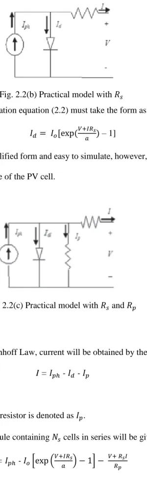
Fig. 2.2(b) Practical model with 𝑅𝑠
When 𝑅𝑠 is taken into consideration equation (2.2) must take the form as in equation (2.5)
𝐼𝑑 = 𝐼𝑜[exp (
𝑉+𝐼𝑅𝑠
𝑎 ) – 1] (2.5)
No doubt fig. 2.2(b) is the simplified form and easy to simulate, however, the following figure fig. 2.2(c) is the most representative of the PV cell.
Fig. 2.2(c) Practical model with 𝑅𝑠 and 𝑅𝑝
In fig. 2.2(c), by applying Kirchhoff Law, current will be obtained by the equation as follows:
I = 𝐼𝑝ℎ - 𝐼𝑑 - 𝐼𝑝 (2.6)
The current leak in the parallel resistor is denoted as 𝐼𝑝.
So, the current output of a module containing 𝑁𝑠 cells in series will be given by:
I = 𝐼𝑝ℎ - 𝐼𝑜[exp (𝑉+𝐼𝑅𝑠
𝑎 ) − 1] −
𝑉+ 𝑅𝑠𝐼
Page | 9 Although the above equation gives a perfect match to the experimental value, however, it is very difficult to determine the parameters of this transcendental equation.
2.3 Determination of Parameters
From the study we have done so far it clear that on the basis of the selected model and the
assumptions made about the model the number of parameters varies. In this project work the four
parameters that have to be determined are 𝐼𝑝ℎ, 𝐼𝑜,𝑅𝑠,𝑅𝑝.
2.3.1 Determination of
𝑰𝒑𝒉:According to fig. 2.2(a), at the standard test conditions (STC), the output current is:
I = 𝐼𝑝ℎ,𝑟𝑒𝑓 - 𝐼𝑜,𝑟𝑒𝑓[exp ( 𝑉
𝑎𝑟𝑒𝑓) – 1] (2.8)
The above equation quantifies for 𝐼𝑝ℎ,𝑟𝑒𝑓, which else could not have been determined. So, the PV
cell on being short-circuited:
𝐼𝑠𝑐,𝑟𝑒𝑓 = 𝐼𝑝ℎ,𝑟𝑒𝑓 - 𝐼𝑜,𝑟𝑒𝑓[exp ( 0
𝑎𝑟𝑒𝑓) – 1] = 𝐼𝑝ℎ,𝑟𝑒𝑓 (2.9)
However, the above equation holds good only for ideal case. And hence, to our assumption we assume:
𝐼𝑠𝑐,𝑟𝑒𝑓 𝐼𝑝ℎ,𝑟𝑒𝑓 (2.10)
Page | 10 𝐼𝑝ℎ = 𝐺
𝐺𝑟𝑒𝑓 (𝐼𝑝ℎ,𝑟𝑒𝑓+ 𝜇𝑠𝑐. ∆𝑇) (2.11)
G: Irradiance (𝑊⁄𝑚2), 𝐺𝑟𝑒𝑓: Irradiance at STC = 1000 𝑊⁄𝑚2, ∆𝑇 = 𝑇𝑐 - 𝑇𝑐,𝑟𝑒𝑓 (Kelvin),
𝑇𝑐,𝑟𝑒𝑓 ∶ Cell temperature at STC = 25 + 273 = 298 K, 𝜇𝑠𝑐 : Co-efficient of temperature for short
circuit current (𝐴⁄𝐾), provided by the manufacturer, 𝐼𝑝ℎ,𝑟𝑒𝑓 : Photocurrent (A) at STC.
2.3.2 Determination of
𝑰
𝒐In the practical single diode model of the PV module as shown in fig. 2.2(c), one of the
important assumption that needs to be noted of is that the shunt resistance 𝑅𝑝 is generally modelled
very large, hence the last term of the equation (2.8) can be eradicated for our subsequent approximation. By applying equation (2.8) at the three notable points at STC: the voltage at open
circuit (I = 0, V =𝑉𝑜𝑐,𝑟𝑒𝑓), the current at short-circuit (V = 0, I =𝐼𝑠𝑐,𝑟𝑒𝑓), and the voltage 𝑉𝑚𝑝,𝑟𝑒𝑓
and the current 𝐼𝑚𝑝,𝑟𝑒𝑓 at maximum power, the following equations can be deduced:
𝐼𝑠𝑐,𝑟𝑒𝑓 = 𝐼𝑝ℎ,𝑟𝑒𝑓 - 𝐼𝑜,𝑟𝑒𝑓[exp (𝐼𝑠𝑐,𝑟𝑒𝑓 . 𝑅𝑠 𝑎𝑟𝑒𝑓 ) – 1] (2.12) 0 = 𝐼𝑝ℎ,𝑟𝑒𝑓 - 𝐼𝑜,𝑟𝑒𝑓[exp (𝑉𝑜𝑐 𝑎𝑟𝑒𝑓) – 1] (2.13) 𝐼𝑚𝑝,𝑟𝑒𝑓 = 𝐼𝑝ℎ,𝑟𝑒𝑓 - 𝐼𝑜,𝑟𝑒𝑓[exp (𝑉𝑚𝑝,𝑟𝑒𝑓+ 𝐼𝑚𝑝,𝑟𝑒𝑓 . 𝑅𝑠 𝑎𝑟𝑒𝑓 ) – 1] (2.14)
Page | 11 As it is very well known that the term (-1) in all the above equations, are, very small compared to the exponential term, hence there is no wrong in eliminating the (-1) term. As stated by equation
(2.11), and by replacing the value of (𝐼𝑝ℎ,𝑟𝑒𝑓) in equation (2.14):
0 𝐼𝑠𝑐,𝑟𝑒𝑓 - 𝐼𝑜,𝑟𝑒𝑓 exp (𝑉𝑜𝑐,𝑟𝑒𝑓 𝑎𝑟𝑒𝑓 ) (2.15) So: 𝐼𝑜,𝑟𝑒𝑓 = 𝐼𝑠𝑐,𝑟𝑒𝑓exp ( −𝑉𝑜𝑐,𝑟𝑒𝑓 𝑎𝑟𝑒𝑓 ) (2.16)
The reverse saturation current is defined by:
𝐼𝑜 = D𝑇𝐶3 exp (−𝑞∈𝐺
𝐴 . 𝑘) (2.17)
∈𝐺: Material band gap energy (eV), 1.12 eV for Silicon.
D: Diode diffusion factor.
In order to remove the factor D (i.e. Diode diffusion factor), equation (2.18) is evaluated two times:
at 𝑇𝐶 and at 𝑇𝐶,𝑟𝑒𝑓 followed by writing the ratio of the two equations in the next expression as
shown in H. Bellia et. al. [6] as follows:
𝐼𝑜 = 𝐼𝑜,𝑟𝑒𝑓( 𝑇𝑐 𝑇𝑐,𝑟𝑒𝑓) 3 exp[(𝑞 . ∈𝐺 𝐴 . 𝐾)( 1 𝑇𝑐,𝑟𝑒𝑓 - 1 𝑇𝑐)] (2.18)
Page | 12 𝐼𝑜= 𝐼𝑠𝑐,𝑟𝑒𝑓exp (−𝑉𝑜𝑐,𝑟𝑒𝑓 𝑎𝑟𝑒𝑓 ) ( 𝑇𝑐 𝑇𝑐,𝑟𝑒𝑓) 3 x exp [(𝑞 . ∈𝐺 𝐴 . 𝐾)( 1 𝑇𝑐,𝑟𝑒𝑓 - 1 𝑇𝑐)] (2.19)
Equation (2.19) offers 𝐼𝑜 with (𝑉𝑜𝑐,𝑟𝑒𝑓, 𝑇𝐶,𝑟𝑒𝑓), parameters given by the firms, others, linked to the
technology of the PV cell, as (A, ∈𝐺) and some constants. But “a” and 𝑇𝐶 are dependent on actual
temperature. Hence, 𝐼𝑜 needs to be determined in real time.
2.3.3 Determination of
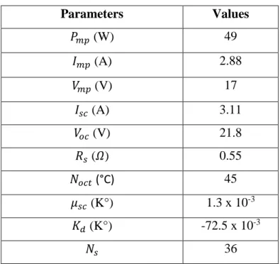
𝑹𝒑and 𝑹𝒔So as to design the planned model more accurate and dependable, 𝑅𝑝 and 𝑅𝑠 are so chosen
that the evaluated maximum power 𝑃𝒎𝒑is equal to the experimental one 𝑃𝑚𝑝,𝑒𝑥at STC. So it is
feasible to write the following equations:
𝐼𝑚𝑝,𝑟𝑒𝑓 = 𝑃𝑚𝑝,𝑟𝑒𝑓⁄𝑉𝑚𝑝,𝑟𝑒𝑓 = 𝑃𝑚𝑝,𝑒𝑥⁄𝑉𝑚𝑝,𝑟𝑒𝑓 = 𝐼𝑝ℎ,𝑟𝑒𝑓 - 𝐼𝑜,𝑟𝑒𝑓[exp (𝑉𝑚𝑝,𝑟𝑒𝑓+ 𝐼𝑚𝑝,𝑟𝑒𝑓 . 𝑅𝑠 𝑎𝑟𝑒𝑓 ) – 1] - 𝑉𝑚𝑝,𝑟𝑒𝑓+ 𝐼𝑚𝑝,𝑟𝑒𝑓 . 𝑅𝑠 𝑅𝑝 (2.20)
So, from the above equation i.e. equation (2.20) we can easily determine the value of 𝑅𝑝just by
rearranging the terms. The repetition commences at 𝑅𝑠= 0 that should grow so as to shift the
Page | 13
power point. Calculation of corresponding 𝑅𝑝 is then done. A single pair (𝑅𝑝, 𝑅𝑠) satisfies this
condition. Parameters Values 𝑃𝑚𝑝 (W) 49 𝐼𝑚𝑝 (A) 2.88 𝑉𝑚𝑝(V) 17 𝐼𝑠𝑐 (A) 3.11 𝑉𝑜𝑐 (V) 21.8 𝑅𝑠 (𝛺) 0.55 𝑁𝑜𝑐𝑡 (°C) 45 𝜇𝑠𝑐 (K°) 1.3 x 10⁻³ 𝐾𝑑 (K°) -72.5 x 10⁻³ 𝑁𝑠 36
Table 2.1 Parameter values of the modeled PV module
2.4 Conclusion
So, from this chapter we saw how to model a PV module that was precise as well as accurate.
This model is first designed on the basis of the basics of semiconductor science and the cell technology. To say it the other way round, the parameters of the module have been selected depending on the parameter variations with irradiation and temperature. So to establish the module parameters for any type of PV module one can use this model and hence plot the module characteristics. To study the behavior of all other kinds of PV modules one can consider this module as a helping hand, principally, their nature under different environment data of standard test conditions (STC). However, the plots of the I(V) and P(V) characteristics for various
Page | 14
CHAPTER 3
Maximum Power Point Tracking Algorithms
3.1 Introduction
Chapter 2 completely covered as well as described the important facts of the PV modeling as well as the traits regarding the current vs the voltage plot of the PV module and its enslavement upon the much discussed parameters, the unpredictable temperature variation and the photon energy or the irradiation variables. [8] says that the research on PV generators has provided us with a vital information that the mutual deviation of temperature as well as irradiation along with the drift phenomenon causes the operating MPP to vary over a wide area. So, as far as the generation of power is concerned, a simple direct connection of the PV module to the input terminals of a DC/DC converter introducing a flat voltage profile can be that simple, however would actually be a poor idea. Say for example, a charger or rather a photo-voltaic battery charger designed by simply attaching the terminals of the photo-voltaic generator to that of the terminals of the energy storing device (battery) would definitely impose the PV module to function at constant voltage. However if this voltage overshoots or gets more than the PV array no-load voltage then the photo-voltaic system would be unable to transmit any power generated. In other
words, as the energy storing device (battery) voltage gets closer to the actual 𝑉𝑀𝑃𝑃, the
photo-voltaic system or the modules start delivering greater amount of power that is generated. Certainly,
because of the time variability property of 𝑉𝑀𝑃𝑃, caused due to the changes in the operating
conditions, a PV array transmitting maximum power at any particular moment of the day is rarely feasible.
Page | 15 We can even draw the exact outcome discussed above considering the following example; while feeding a resistive load, a PV array delivers a power that is not the maximum power rather a power that is lower than the maximum power and this happens because the point of intersection of the resistor plot and the current vs voltage plot of the PV array for an entire day cannot be the maximum power point. So, the array transmits a power that is lower than the maximum power. Hence, from the discussion till now, we can say that the through connection of the photo-voltaic module to the load causes the PV generators to underperform in any temperature or irradiation conditions.
As a result of the conclusion drawn above, a midway changeover stage is mandatory, linking the photo-voltaic array and the DC/DC converter, and that must be proficient in adjusting its input parameter level (i.e. voltage and current levels) to the immediate PV source MPP, keeping its output voltage and current levels in harmony as per the requirements of the load. Such a midway changeover stage can be a “dynamical synthesizer or cheaply can be said as converters” that must be capable of adjusting to this situation in the company of time-varying operational conditions hampering the PV modules. The application of a switching converter is almost always employed. So as to make sure the extraction of the maximum power from the PV source, the linking DC/DC power processor should adjust on its own the parameters at the execution time, thereby altering the parameter levels (voltage & current levels) in accordance to the MPP position. Throughout the project work, the “dynamic synthesizer or the optimizer” has been a DC/DC
converter and the converters duty cycle d is the control parameter, as shown in figure (3.1).
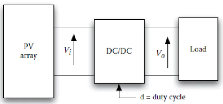
Page | 16 Fig. 3.1 Block diagram of a PV system consisting of a dedicated DC/DC converter.
It is this, MPPT regulator that invariably adjusts the DC/DC optimizer duty cycle d, so as to track
the true MPP as depicted in figure (3.2). There are various methods and algorithms available for the MPPT control, the Perturb & Observe (P&O) and the Incremental Conductance (INC) algorithms being the most popular. The Incremental Conductance being the superior algorithm to the Perturb & Observe algorithm. This chapter, exclusively is dedicated to the explanation of the Perturb & Observe algorithm. The direct duty ratio control has been mostly focused upon.
Page | 17
3.2 Fractional Open-Circuit Voltage
The following equation shows a direct relationship between the Maximum power point voltage and the PV panel open-circuit voltage.
𝑉𝑀𝑃𝑃 = 𝐾𝑉𝑉𝑂𝐶 (3.1)
Constant 𝐾𝑉, is always dependent on the type and the configuration of the solar panel. From the
above equation we see that, to know the MPP point we need to know the open-circuit voltage of the PV panel. One way to calculate the no-load or the open-circuit voltage is to periodically disconnect the load from the system and calculate the no-load or open-circuit voltage and hence the maximum power point voltage. It has been experimentally found out that the Maximum power point voltage is around 76% of its open-circuit voltage. However, during this disconnection of the system from the load, causes huge waste of power because throughout this disconnection no power is being transmitted. We can also obtain the no-load voltage by using a number of monitoring cells however they must also be selected and positioned very cautiously to calculate the correct open-circuit voltage. However simple and robust this system might be, we can only make rough estimation of the MPP.
3.3 Fractional Short-Circuit Current
The short-circuit current can also be used to evaluate the MPP, as it shares a linear relationship with the current at MPP for various atmospheric conditions. The following equation shows the relationship
Page | 18
Recording 𝐼𝑆𝐶 is more of a hectic job than recording 𝑉𝑂𝐶, as it not only heads towards power losses
and heat dissipation, but also demands extra switches and current sensing elements that buildup
the price of set up. It has been experimentally found that the 𝐼𝑀𝑃𝑃 is around 86% of its short-circuit
current 𝐼𝑆𝐶.
3.4 Incremental Conductance
It runs around the theory that the gradient of the power vs voltage characteristics is zero at MPP, having positive gradient on the left side and negative gradient on the right side of MPP. The algorithm in terms of equations are as follows:
Equation 1: 𝑑𝑃 𝑑𝑉
= 0,
at the MPP 𝑑𝑃 𝑑𝑉> 0,
left of MPP 𝑑𝑃 𝑑𝑉< 0,
right of MPP Equation 2: 𝑑𝑃 𝑑𝑉=
𝑑(𝐼𝑉) 𝑑𝑉=
I
+
V
𝑑𝐼 𝑑𝑉=
I + V
∆𝐼 ∆𝑉Page | 19 ∆𝐼 ∆𝑉
= -
𝐼 𝑉,
at MPP∆𝐼 ∆𝑉
> -
𝐼 𝑉,
left of MPP∆𝐼 ∆𝑉
<
-𝐼 𝑉,
right of MPPIt is basically a concept of making a comparison between the incremental conductance and the
instantaneous conductance, and this logic is run unless and until the MPP is reached either by increasing or by decreasing the voltage.
3.5 Perturb & Observe (P&O)
The P&O MPPT algorithm is one of the popular direct MPPT algorithms available and is characterized by injecting a minor change into the system, thereby using the effects to make the operating point shift towards MPP. The P&O MPPT algorithm stands out of other direct MPPT algorithms moreover for the detected parameter or for the type of perturbation. Out of the available MPPT algorithms, each algorithm have one thing in common, that they have got no knowledge about the type of PV generator characteristics, yet the MPP is traced irrespective of the irradiation intensity, temperature, aging, thus giving us a robust and reliable system.
The P&O follows the following concept: What the controller over here does is, it keeps perturbing periodically the PV operating point by altering the voltage at PV source terminals. Followed by each change, the controller evaluates the power delivered by the PV source before and after each change, and if after the change the PV power has got beyond the previous value, then it is ensured that the operating point has shifted towards the MPP. Accordingly, due to the subsequent perturbation applied on the voltage the sign remains the same as the earlier one.
Page | 20 Similarly, if after a minor change in voltage causes the PV power transmitted to have decreased, then it can be for sure inferred that systems point of operation has moved far from the MPP. Thus, we can say that due to subsequent voltage changes the sign has reversed or changed. The switching converter or the DC/DC converter is the DC/DC optimizer that drives the changes of the effective voltage of the PV modules.
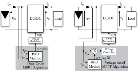
There are available two common P&O configurations that can be used to control the switching converter as well as realize the voltage changes. The first basic or common configuration involves
the direct change of the duty cycle of the switch and the second configuration being the change or
the perturbation of the reference voltage of an error amplifier that creates the signal controlling the duty cycle. Both the configurations have been shown in the figure that follows:
Fig. 3.3 Basic P&O configurations
In the figure (3.3) shown above, the first configuration operates without any feedback loop after each individual change; whereas the second configuration has a voltage feedback loop.
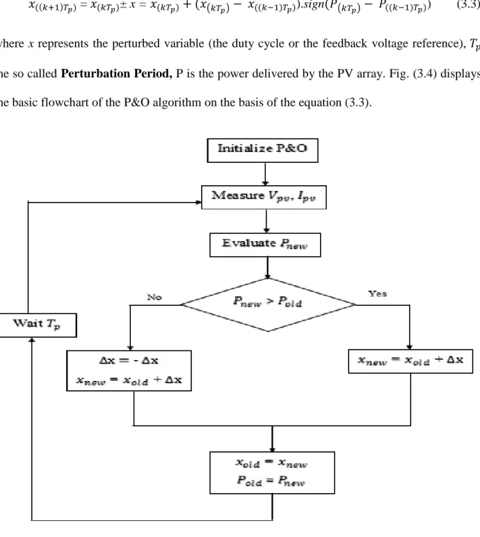
Page | 21 𝑥((𝑘+1)𝑇𝑝) = 𝑥(𝑘𝑇𝑝)± x =𝑥(𝑘𝑇𝑝)+ (𝑥(𝑘𝑇𝑝)− 𝑥((𝑘−1)𝑇𝑝)).sign(𝑃(𝑘𝑇𝑝)− 𝑃((𝑘−1)𝑇𝑝)) (3.3)
where x represents the perturbed variable (the duty cycle or the feedback voltage reference), 𝑇𝑝
the so called Perturbation Period, P is the power delivered by the PV array. Fig. (3.4) displays
the basic flowchart of the P&O algorithm on the basis of the equation (3.3).
Fig. 3.4 Basic flowchart for P&O MPPT algorithm.
The main disadvantage occurring in the P&O MPPT algorithm is that, once the functioning point reaches near the MPP, the control algorithm makes the system to oscillate about the MPP. About this point the system loses energy. Selecting a minor step size minimizes the disturbances close to
Page | 22 the MPP, however it adversely enhances the tracking time. Choosing a larger step size causes increase in power loss and reduction in tracking time.
3.6 Improvement of the P&O algorithm
So, from the discussions as of now, we know that of all the available MPPT algorithms, the P&O MPPT algorithm is the most chosen and widely used. The demand for this MPPT is more because of its simplified control design and the simplicity in its application. However in the
application of this algorithm, fixed [∆𝑥, 𝑇𝑝] parameters an appropriate situation must be attained
so as to select the controller values for matching the losses during steady state due to large changes around the MPP and the MPPT rate in conditions engaging rapidly changing irradiation conditions
or load. By optimizing the values of the perturbation amplitude ∆𝑥 and the sampling period 𝑇𝑝 lots
of benefits are derived, yet, having so many advantages the performance of the P&O MPPT algorithm can still be improved. The following are the two methods available to improve the performance of P&O MPPT algorithm:
Adaptive step-size P&O.
Parabolic Approximation P&O.
3.7 Conclusion
So, in this chapter we exclusively discussed about the design and the need for an MPPT algorithm. Briefly, we know that the I(V) characteristics of the PV generators are non-linear, and the PV power obtained of an optimum PV array due to the prevailing operating conditions is influenced by erratic insolation, temperature of the cell as well as the load conditions. Thus, a
Page | 23 controller to track the maximum power point is required continuously in order to match the PV array internal resistance to its loading so that during its entire operation maximum power is delivered to its load. Then we saw the various MPPT algorithms that are available to date. Out of those MPPT algorithms the Fractional open-circuit voltage and the Fractional short-circuit current algorithms are practically not sound enough for all conditions. These two methods are like approximation methods. We cannot get the exact MPP point if the two control methods are used. Then, we got some basic ideas about the Incremental Conductance method which is the so called improved version of the Perturb & Observe MPPT algorithm. The Incremental Conductance method tracks the MPP a bit faster than the P&O algorithm. However, the demand for the P&O algorithm has been high and research on this algorithm is still going on because of its robustness and easiness of implementation. As we know, to have something we have to compromise something else for it, here when we use the P&O algorithm no doubt it is a robust system but it makes the system lose power when the operating point reaches MPP. This loss is basically due to the oscillating nature of the algorithm around the MPP. After all those study we have finally seen that even the P&O algorithm can be improved and indeed there are two available methods to do it.
Page | 24
CHAPTER 4
Distributed Maximum Power Point Tracking
4.1 Introduction
Since we have displayed a solitary PV module and devoted with it, its own particular MPPT calculation and DC/DC converter, handy PV frameworks oblige PV modules to be associated in arrangement so as to get higher string voltages. In any case, because of different variables like halfway shading, assembling crisscross, maturing impacts and warm inclinations the I-V attributes bungles are regularly recognized between arrangements joined PV modules. As we realize that, in a series of arrangement associated PV modules all modules share a typical current, this can diminish the general force yield of the string as a result of the failing to meet expectations modules. In this way, to conquer this sensation customarily sidestep diodes were utilized or they were joined as a part of parallel over each PV module to address this confuse wonder and module hot spotting. Notwithstanding, the utilization of detour diode doesn't enhance the framework effectiveness and the framework productivity stays still noteworthy if a solitary focal converter was utilized to perform MPPT. The accessible most essential arrangements are DC/DC converters, and the inverters. However the downsides of these two arrangements, is that these conveyed converters needs to process the whole power yield of each module or sub-module. Again after utilization of proficient conveyed converters writing says that the frameworks general force misfortunes stays huge. Taking all impacts and the misfortunes into thought, an investigation of the appropriated structural engineering still stays overwhelming as it pleasantly addresses for the issues of incomplete shading, assembling crisscross, maturing impacts and warm angles. As we go further
Page | 25 into the part we will see the different sorts of circulated architectures and how they are actualized basically.
4.2 Limitation of Standard MPPT
Normally the PV systems are seen to adopt classical maximum power point tracking, i.e., the maximum power point (MPP) tracking in the power vs. voltage (P-V) characteristic of the entire system that is filled with paralleled PV strings as shown in Figure (4.1).
Fig. (4.1).Paralleled string of PV modules connected to single DC/AC converter
However in instances of jumble because of shadows, mists, maturing, fabricating resilience, foulness, variable orientation of PV field, and so forth., the P-V normal for the PV framework shows more than a crest in the PV qualities, because of the use of the bypass diodes, and Maximum
Page | 26 power point following calculations come up short, subsequently lessening the general framework productivity unless and until the whole PV trademark is cleared intermittently [8]. In spite of the fact that the FMPPT has the capacity track indisputably the greatest point (force point) of the befuddling PV array, such a power is much lower than the entirety of the accessible most extreme powers that the mismarch modules have the capacity to give.
4.3 Distributed MPPT: A Novel Methodology
The study of PV systems has so far revealed that the extraction of maximum power out of the modules using standard MPPT has many drawbacks. Out of those drawbacks the one that needs to be addressed is the mismatching phenomenon. So, the solution that is being received to address the downsides connected with the mismatch phenomenon in PV systems is known as the distributed MPPT. The Distributed MPPT requires or has two approaches that has been discussed in this chapter. The first being the application of the module-level micro-inverters, and having the tracking algorithm for each and every PV module. The second methodology being the use of module-level dedicated DC/DC converters, having the MPPT algorithm for each and every module and centralized DC/AC converters.
4.3.1 Distributed MPPT using Micro-Inverters
In general a micro-inverter is a DC/AC converter that is connected to the grid and it is used to transform the direct power supply from an individual PV module to load (grid) required AC power as well as it carries out the Maximum power point tacking on modules such as shown in Fig. (4.2).
Page | 27 The pros obtained adopting the Micro-inverter based DMPPT method are as follows:
In case of mismatching the loss of available PV energy in the system is greatly checked.
Since the micro-inverters can be easily paralleled on the AC side of the systems, the number
of PV systems can be expanded easily thus obtaining the advantage of Modularity.
In such an approach we have the advantage of Reliability, since the modules operate
independently. There is nothing to worry if one or two of the modules stop operating. The healthy modules still operate and transmit power to load.
The size of the system can be reduced to a greater extent. It means the threshold for
individuals for stating their own PV plant is reduced.
No DC cabling is required thus reducing the cost of installation and the design of the
system.
No need of bypass diodes or the string diodes and therefore reduction of additional
conduction losses.
Yet so far we saw the aces of the smaller scale inverter based DMPPT framework. Then again, this would be similar to a perfect framework if it comprised of preferences. Small scale inverter based DMPPT framework likewise have a few cons or burdens. To begin with, the lower level of power in the scope of couple of watts, which permits a base buy esteem, additionally unequivocally influences the expense following the negligible the power rating, the higher the expense of per kWh created.
Page | 28 Fig. (4.2) Micro-inverter based DMPPT system.
Notwithstanding, with a specific end goal to minimize costs, generation in mass is a required condition and that must be achieved by method for supple arrangements sufficiently effective of working with a large portion of the boards accessible in the business. This clearly indicates the need of having high-voltage-pick up capacity in light of the fact that PV boards for the most part have yield voltages in the range of [20-45] V. Not too bad up till now, be that as it may, the muddling associated to the configuration basically of a small scale inverter can be portrayed by the prerequisite voltage enhancement from the minimum level of DC of the modules to the level of AC commonplace of Indian framework 230 V (RMS). Besides, AC grid get together points of interest, for example, insurance, control, and separating, including hostile to islanding, should all be spread to every board converters, and this sponsors to keeping raised the financial expense of force produced by the modules utilizing the miniaturized scale inverter based DMPPT frameworks.
Page | 29 Another shortcoming is characterized by the obligatory system necessity of highly robust power electronics with longer durability (generally expected to be the lifespan of a PV module i.e. 20-25 yrs.). Thus reliability and level of failure of components are directly dependent on lifetime. Moreover, serious ecological circumstances are plausible with an extensive variety of temperature inconsistencies amid a day, and thusly additionally mechanical weights on modules and protection equipment's. Amongst all components dynamic or inactive, the electrolytic capacitors are the ones that are minimum strong or are having the most brief lifetime, adding to it is the maturing impact, which with the progression of time expands the Equivalent Series resistance (ESR) subsequently expanding the power misfortunes. The energy holding capacity needed for single-stage AC association to isolate the input side from the grid side requests the need for energy holding capacitors, in all cases is the electrolytic capacitors. Accordingly an AC module is the mix of a solitary PV module and a solitary DC/AC converter that changes over photon vitality into AC power when it is paralleled to the PV system.
In literature, the series connection of the output terminals of micro-inverters so as to achieve direct 230 V AC grid (transformer-less) connection is also feasible. Such a design is promising and warrants additional attention and study. No marketable devices of this kind are at present available.
4.3.2 Distributed MPPT using dedicated DC/DC Converters
As we have discussed already at the start of Section 4.2, the second methodology adopted to address the drawbacks associated with mismatching phenomena is based on the adoption of MPPT module-dedicated DC/DC converters Figure (4.3) and centralized inverters.
Page | 30 Fig. (4.3) DMPPT using dedicated DC/DC converter.
4.4 PV array with DMPPT- DC Analysis
In this segment, those PV frameworks that embrace the model demonstrated in Figure 4.3 will be talked and inspected completely since the association in arrangement of the output terminals of the DC/DC converters exacts some nontrivial limits that needs to be judiciously made note of, if the effective PV framework working is favored. Henceforth, a framework embodied by a PV module with a devoted DC/DC converter will be meant as a self-controlled PV module (SCPVM). Be that as it may, there exists two fundamental weaknesses of the DMPPT capacities. The main being typified by the component that DMPPT is capable of ensuring better energy efficiency over field maximum power point tracking (FMPPT), in the presence of mismatch, the length of the viability of the power phase of MPPT DC/DC converters is sufficiently high. The second weakness being encapsulated by the component that circumstances win in which even the DMPPT methodology
Page | 31 permit is not granted to operate each PV module of the array at its MPP. Alternately we can say that, by embracing the DMPPT approach, the power developed by the PV array can be as low as than the aggregate of the greatest accessible power of the individual modules, besides, it can likewise be lower than the force removed by receiving the FMPPT approach. This highlight is not just connected to restrictions joined with the moderately constrained voltage change proportion of the specific DC/DC converters embraced. Evidently, areas of DMPPT operations may happen not just when utilizing a topology (e.g., the boost one) that is capable just to expand the output voltage concerning the input voltage, additionally when utilizing DC/DC topologies, for example, the Cuk and Buck-Boost topologies, which have the capacity to venture up or venture down the output voltage as for the input voltage, and that subsequently, at first look, might be examined to allow the foreseen exhibitions of DMPPT applications in whichever working condition. Actually, inferior to expected DMPPT exhibitions can likewise happen due to the constrained evaluations of gadgets used in the force phase of SCPVMs or due to a non-ideal estimation of the string voltage.
4.4 Conclusion
On field or practically where large number of PV modules or arrays are installed one of the major issues that needs to be addressed is the mismatching phenomenon. Mismatch may occur due to various reasons (mainly manufacturing mismatch, ageing, irregular irradiation, dirtiness etc.). So this chapter gave a brief idea about how to address the mismatching phenomenon.
Page | 32 Distributed MPPT helps to model a system that has innumerable advantages compared to the standard MPPT algorithm. We saw that there are two methods to perform the DMPPT namely: DMPPT using micro-inverters and other DMPPT using dedicated DC/DC converters. The project work has adopted the second method i.e. DMPPT using the dedicated DC/DC converters where we will see in further chapters that it has improved the system efficiency.
Page | 33
CHAPTER 5
Cross-Coupling Effects in Distributed DC/DC converters in PV
applications
5.1 Introduction
To address power dives due to mismatch and unanticipated aging impacts or breakdowns, the reception of a dedicated switching converter to every photo-voltaic module is one of the attainable clarifications. Granular regulation of photovoltaic (PV) modules is the novel driving edge of PV innovation. It is all around appreciated that a shadow concerning no less than a solitary module out of a whole series of arrangement associated PV boards' bargains the power generation of the whole string. Every time an extensive number of module get two or much more distinctive illumination levels, the P(V) normal for the PV string reveals various tops, with the standard (MPPT) calculation following the maximum power point may not be the definite one. Such a state additionally happens if harmed boards in a string are substituted by different ones with differing electrical attributes, thus making challenging the speedy re-foundation of the PV power plant unless a substitution is existing. The regularly expanding tying of PV innovation offers ascend to further muddlings: PV generators with unalike introductions can't be appended in arrangement and managed by a solitary MPPT controller, until and unless an impressive deal in the power generation is acknowledged. In writing, numerous contemporary distributions recommend novel arrangements and architectures for the granular control of the PV modules, dc/ac converters, or in view of dc/dc converters. In the business sector, both these arrangements have as of now been recommended by a few organizations. The configuration in view of the reception of a dc/dc converter for each PV module allows a granular MPPT capacity. Then again, some new intricacy
Page | 34 emerges in the association of the dc/dc' yields to the information terminals of either a devoted dc/ac arrangement or a commercial PV inverter.
As a matter of information, if in the series connection of the dc/dc converters’ output terminals, some of the PV modules obtain an irradiation that is considerably lower than that gained by the other modules, the dc/dc converters dedicated to the latter ones share, at their output terminals, almost the entire dc bus voltage. The output voltage of each dc/dc converter in a string of dc/dc converters is proportionate to the power extricated by its own PV module. The more the power extricated by its own PV module, the higher the output voltage of the dc/dc converter. Irrespective of the model adopted for the dc/dc converters, this transmutes in higher stresses for the semiconductor devices. A high voltage boosting factor is required for parallel connection of the dc/dc converters’ outputs, on the other hand this obligatory aspect makes the attainment of a high dc/dc converter efficiency a really intricate task.
In both cases communicated some time recently, make utilization of independent dc/dc units, every one of them including a dc/dc converter utilizing the MPPT work autonomously of alternate units devoted to alternate modules of the PV array. Such a structural planning affirms a definitive level of seclusion and licenses to remove the greatest power from every module, on the other hand to lead the MPPT at a module dedicated level, a single voltage and current detecting component for individual PV module in the string is crucial. Certainly, MPPT control procedures without the present detecting component oblige a more mind-boggling calculation and showcase poorer exhibitions.
As in [6], the input terminals of the DC/DC converters are devoted to every individual PV module. The divergence concerning the methodology talked about in [6] that can be esteemed as the traditional one in DMPPT is in the way that the control strategy introduced in this section is
Page | 35 built up on a centralized MPPT controller. The MPPT controller runs a multivariable Perturb and Observe calculation that settles, with a suitable arrangement, the duty cycle of each of the dc/dc converters in the string. The control method is planned for augmenting the power at the dc bus and thus requires to detect one output voltage and one and only current. This endeavor grants to keep the utilization of a high number of current sensors, however in [6], to minimize the expense and to enhance the adequacy and consistency one and only current sensor has been utilized. The proposed system can be embraced to both the doable architectures, to be specific with the dc/dc converters output associated in parallel and with the dc/dc converters' output joined in series. The MV system bothers the working purpose of one module just in every interim Ta describing the P&O operation, however in the single variable (SV) strategy, the working purposes of the considerable number of modules, or possibly a piece of them, managed by a solitary unit are perturbed in every interim Ta.
5.2 Witnessed Cross-Coupling Effects
Commonly, broad PV power frameworks comprises of long strings of PV modules that are by and large interfaced to the network framework with the assistance of a DC/AC converter. Those strings contain various PV modules associated in series, subsequently heightening the voltage of the string sufficiently high for the converter. However in the PV field these strings have been distinguished to be helpless to shading impacts, where the modules that are shaded fail to meet expectations and the generated power produced by such modules are restricted [10]. Only on account of series association, every module needs to convey break even with current that powers the working purpose of a few modules far from the MPP. To beat this, DMPPT frameworks have been recommended, where each PV module has got a dedicated interfacing converter.
Page | 36 In a dual staged transformation chain, DMPPT converters are the first part, in which the dc power developed by the PV strings is injected inside the grid with the assistance of a DC/AC converter. The two-stage transformation chain along these lines contains, a dc connection (high-voltage) i.e. DC/DC converters and the DC/AC converters. Routinely, there are number of converters injecting power inside the basic dc join. The general structural planning of DMPPT frameworks have been indicated in Figs. 5.1 and 5.2, portraying the series design and the parallel setup, individually. On the off chance that we find in Fig. 5.1, the series design has the outputs of interfacing converters joined in series. In this manner, the dc-join voltage is circulated among the converter output terminals as indicated by power levels [9]. However in the event that we find in Fig 5.3, the parallel arrangement has the output terminals of the interfacing converters associated straightforwardly to the dc join i.e., to the input of DC/AC converter, because of which, every converter needs to shoulder whole dc-join voltage at the output terminal, which requests some particular solution to meet this high transformation ratio.
The ideas managing DMPPT have been under thorough study, with number of distributions debating the configuration procedure of interfacing dc–dc converters and usage of MPP following. Notwithstanding all the exploration work done on the theme, there scarcely exists any paper giving a clear and complete element examination for DMPPT frameworks. Siri et al. distributed a paper examining MPP following in parallel arrangement, however the dynamic considerations are construct just with respect to a solitary converter. Out of all distributions, the most exhaustive element contemplations have been displayed by Femia et al. [6], in which an arrangement of two series joined converters is examined and a little flag model is displayed. Nevertheless, the talked about results have just limited anticipating power, potentially because of presentation challenges and accentuation on the soundness subjects. Case in point, the model composed by Femia et al. is
Page | 37 not able to record for the cross-coupling impacts that have been seen in reenactments by Petrone et al. [5]. The undesirable properties of cascaded converters that causes unsettling influences in the operations of the converters are fundamentally termed as cross-coupling impacts [5].
Fig. (5.1) Series DMPPT structure.
Fig. (5.2) Parallel DMPPT structure.
The cross-coupling impact happens because of the poor MPPT execution which is because of the way that at whatever point there is a sudden or step change in the illumination level there is a quick output voltage variation of the corresponding DC/DC converter followed by an adjustment in the data power. Because of this, alternate converters are influenced by this unsettling influence and
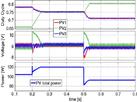
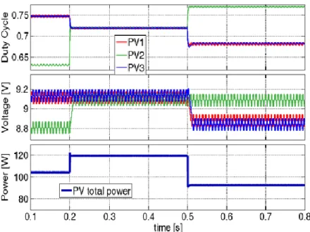
Page | 38 subsequently their individual controllers change the duty cycles of the converters with a specific end goal to remunerate it. Performances of the applied algorithm deteriorates whenever step changes in irradiation occurs, as it requires some time for the framework to reach new consistent state conditions. Regarding following speed, the execution of the calculation can be enhanced by applying feedback control of the PV voltages to make the PV voltage itself less touchy to irradiance changes. A pleasant case on cross coupling impacts and its effect has been introduced in [5]: where an arrangement of three series joined converters was assessed by applying an irradiance succession into PV modules connected to every converter. To start with being worked in an open-loop MPPT mode, where the MPPT piece gave duty cycle to converters specifically and in closed-loop MPPT mode, where the MPP tracker gave reference value for input-voltage feedback loop. The reproduction results performed on both closed-loop and open-loop mode as demonstrated by Petrone et al. [5] are demonstrated in Fig. 5.3 and Fig. 5.4 as takes after.
Page | 39 Fig. 5.4 Closed loop MPPT mode.
5.3 Conclusion
So, in this chapter we saw the various DMPPT configurations as well as the cascaded connection of the DC/DC converters with the PV modules. In series connected systems it was shown that due to sudden variation in irradiation disturbances known as cross-coupling effects occur that affects the operation of other DC/DC converters. Whereas as in parallel configuration invariably cross-coupling effects are absent unless some non-ideal properties are injected into the system load. However in order to overcome the cross-coupling effects in series connected systems we need to apply input-voltage feedback control.
Page | 40
CHAPTER 6
Results & Discussions
Results
In this chapter or section we are going to see the various simulated results that have been obtained throughout the project work right from the plotting of the I-V and the P-V characteristics to the detection of the cross-coupling effects in the distributed converter connections. Along with the results certain important features have been pondered over to get a clearer idea about why such things happen.
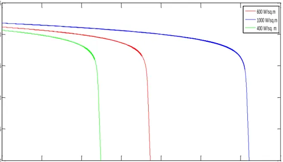
The plot below shows the I-V characteristics of a PV module for different solar insolation:
Fig. 6.1 I-V characteristics of the simulated PV module for varying irradiation value and constant temperature. 0 0.5 1 1.5 2 2.5 3 3.5 0 5 10 15 20 25
PV Current (in Amp)
P V V o lt a g e ( in V o lt s ) 600 W/sq.m 1000 W/sq.m 400 W/sq. m
Page | 41 The following plot is the PV characteristics of the simulated PV module for different values of irradiation and constant temperature:
Fig. 6.2 PV characteristics of PV module for varying irradiation and constant temperature.
The two graphs shown above are very easy to interpret and hence few things can be noted off about the PV modules or the PV characteristics viz.
At constant temperature as the level of irradiation grows,
The level of output current also changes or rather increases.
The level of output voltage also ascends and hence the total output power increases when
the irradiation level increases at constant temperature.
The following figure depicts the variation of module output voltage with respect to its current
under constant irradiation of 1000 W/m2 and varying temperature and the result is as follows:
0 5 10 15 20 25 0 10 20 30 40 50 60
PV Voltage (in Volts)
P V P o w e r (i n W a tt s ) 400 W/sq. m 600 W/sq. m 1000 W/sq. m
Page | 42 Fig. 6.3 I-V characteristics of the PV module for constant irradiation & varying temperature.
Similarly, the following fig. shows the P-V characteristics for constant irradiation and variable temperature:
Fig. 6.4 P-V characteristics of PV module for constant irradiation and varying temperature.
0 0.5 1 1.5 2 2.5 3 3.5 0 5 10 15 20 25 Current in Amps V o lt a g e i n V o lt s 25 degree celsius 50 degree celsius 75 degree celsius 0 5 10 15 20 25 0 10 20 30 40 50 60 Voltage in Volts P o w e r in W a tt s 75 degree celsius 50 degree celsius 25 degree celsius
Page | 43 There are few more points that needs to be noted off as it has been verified and they are:
At the increase of temperature,
There is hardly any change in output current or rather increases slightly.
Whereas there is a tremendous drop in the output voltage that causes the output power to
drop.
The following figure shows the PV boost voltage, in which we can see switch of voltage levels with the switch in the irradiation level.
Fig. 6.5 PV Boost Voltage for varying irradiation
In the above plot the top most level corresponds to an irradiation level of 1000 W/m2 following
the middle layer with an irradiation level of 800 W/m2 and then the lower level and that
corresponds to an irradiation level of 400 W/m2.
Similarly, the plot for the PV boost current for different values of irradiation would be as follows:
0 1 2 3 4 5 6 7 8 0 20 40 60 80 100 120 140 160
Time (in secs)
P V B o o s t V o t a g e ( in V o lt s )
Page | 44 Fig. 6.6 PV boost current for varying irradiation.
The following plot shows the individual PV voltages of two series-connected modules indicating the existence of Cross-Coupling Effects:
Fig. 6.7 PV Module Voltages showing CCE
0 1 2 3 4 5 6 7 8 0 0.05 0.1 0.15 0.2 0.25 0.3 0.35
Time (in secs)
P V B o o s t C u r r e n t ( in A m p s ) 0.050 0.1 0.15 0.2 0.25 0.3 2 4 6 8 10 12 14 16 18 20
Time (in secs)
P V V o lt a g e ( in V o lt s ) PV Voltage Module 1 PV Voltage Module 2